Pfaff 3819 series User manual

This instruction manual applies to machines
from the following serial numbers onwards:
2 808 742 and software version 0441/001.
3819
296-12-19 290/002
Instruction Manual engl. 10.15
INSTRUCTION MANUAL
-20/02
-40/01

This instruction manual applies for all of the models and subclasses listed in
Chapter 3Technical Data.
Reprinting, copying and translation - including excerpts - from
PFAFF instruction books is permitted only with our prior approval
and listing of sources.
PFAFF Industriesysteme
und Maschinen GmbH
Hans-Geiger-Str. 12 - IG Nord
D-67661 Kaiserslautern
The adjustment manual for the machine can be downloaded at no charge
at www.pfaff-industrial.de/de/service-support/downloads/technical. As an
alternative to the Internet download, the adjustment manual can also be
ordered under order no. 296-12-19 291/002.

Table of Contents
Contents ..................................................................................................Page
1Safety .................................................................................................................................... 5
1.01 Directives............................................................................................................................... 5
1.02 General safety instructions .................................................................................................... 5
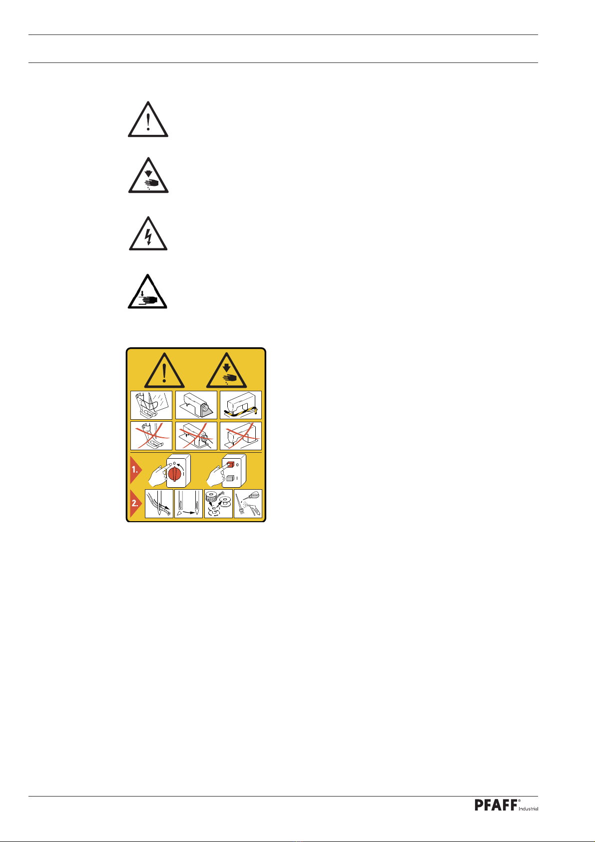
1.03 Safety symbols ...................................................................................................................... 6
1.04 Special points of attention for the owner-operator ................................................................ 6
1.05 Operating personnel and technical staff ................................................................................ 7
1.05.01 Operating personnel .............................................................................................................. 7
1.05.02 Technical staff........................................................................................................................ 7
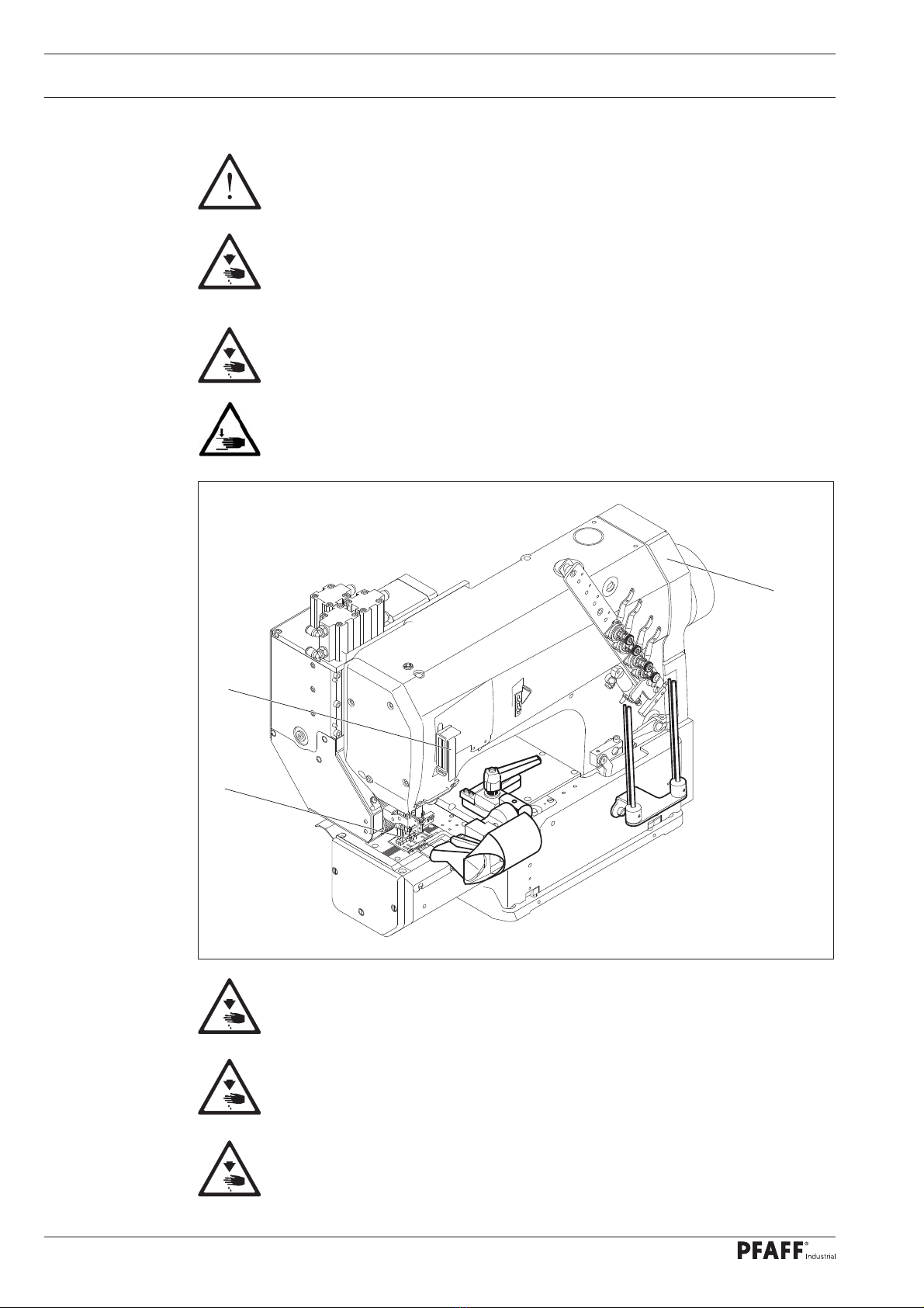
1.06 Danger warnings.................................................................................................................... 8
2Proper Use............................................................................................................................ 9
3Technical Data ................................................................................................................... 10
3.01 PFAFF 3819 ......................................................................................................................... 10
4Disposal of the Machine.................................................................................................... 11
5Transport, Packaging and Storage ................................................................................... 12
5.01 Transport to the customer´s premises ................................................................................ 12
5.02 Transport within the customer´s premises.......................................................................... 12
5.03 Disposal of the packaging materials .................................................................................... 12
5.04 Storage ................................................................................................................................ 12
6Work Symbols.................................................................................................................... 13
7Operating Controls ............................................................................................................14
7.01 Main switch ........................................................................................................................ 14
7.02 Light barrier.......................................................................................................................... 14
7.03 Treadle ................................................................................................................................. 15
7.04 Control panel........................................................................................................................ 16
7.04.01 Symbols on the display........................................................................................................ 17
7.04.02 Plus/minus keys................................................................................................................... 17
7.04.03 Function keys....................................................................................................................... 18
8Set-up and Initial Commissioning .................................................................................... 20
8.01 Set-up .................................................................................................................................. 20
8.01.01 Setting the table height ...................................................................................................... 20
8.01.02 Mounting the reel stand ...................................................................................................... 21
8.02 Connecting the plug-in connections and ground cable ........................................................ 22
8.03 Initial start-up ....................................................................................................................... 23
8.04 Switching the machine on/off ............................................................................................. 23

Table of Contents
Contents ..................................................................................................Page
9Set-up.................................................................................................................................. 24
9.01 Inserting the needle............................................................................................................. 24
9.02 Threading the needle / adjusting the needle thread ............................................................ 25
9.03 Threading the looper thread / adjusting the looper thread................................................... 26
9.04 Fitting the tape reel.............................................................................................................. 27
9.05 Threading the tape into the pleating attachment................................................................. 27
10 Production .......................................................................................................................... 28
10.01 Sewing – automatic mode ................................................................................................... 29
10.02 Sewing – manual mode .......................................................................................................30
10.03 Input mode .......................................................................................................................... 31
10.04 Input mode .......................................................................................................................... 33
10.05 Programming ....................................................................................................................... 34
10.07 Programming ....................................................................................................................... 35
10.08 Programming a trouser waistband....................................................................................... 36
10.09 Parameter list....................................................................................................................... 37
10.10 Program management .........................................................................................................40
10.10.01 Inserting and removing the SD memory card...................................................................... 40
10.10.02 Displaying the machine directory......................................................................................... 41
10.10.03 Displaying the SD card directory.......................................................................................... 42
10.10.04 Copying program(s) to the SD card...................................................................................... 43
10.10.05 Copying program(s) from the SD card. ................................................................................ 44
10.10.05 Deleting program(s) in the machine memory ...................................................................... 45
10.10.06 Deleting program(s) on the SD card .................................................................................... 46
10.10.07 Formatting the SD card........................................................................................................ 47
10.10.08 Error messages.................................................................................................................... 48
11 Maintenance and Care....................................................................................................... 51
11.01 Maintenance intervals.......................................................................................................... 51
11.02 Cleaning the machine .......................................................................................................... 51
11.03 Checking / topping up the oil level of the oil tank for the front parts................................... 52
11.04 Checking / topping up the oil level of the gear mechanism................................................. 53
11.05 Checking / setting the air pressure ...................................................................................... 54
11.06 Emptying / cleaning the maintenance unit´s water tank...................................................... 54
12 Wearing Parts..................................................................................................................... 55

Safety
5
1 Safety
1.01 Directives
The machine was built in compliance with the European regulations specified in the declara-
tion of conformity and declaration of incorporation.
As a supplement to this instruction manual, please also observe the generally applicable,
legal and other regulations and legislation – also in the country of use – and the valid
environmental protection regulations! Always comply with the locally applicable regulations
of the professional associations and other supervisory authorities!
1.02 General safety instructions
The machine may only be operated after you have become acquainted with the associ-
ated instruction manual and only by operating personnel who have received appropriate
training!
Always read the safety instructions and the instruction manual of the motor manufactur-
er before starting up the machine!
Always follow the hazard and safety instructions attached to the machine!
The machine may only be operated for its intended purpose and only with the associated
safety covers, while adhering to all the relevant safety requirements.
The machine must always be disconnected from the power supply by pressing the main
switch or pulling out the mains plug when sewing tools are replaced (such as the needle,
sewing foot, needle plate, feed dog etc.) and when threading, leaving the workstation, or
performing maintenance!
The daily maintenance work may only be carried out by suitably qualified personnel!
Repairs and special maintenance work may only be carried out by technical staff or peo-
ple with appropriate training!
Unless otherwise stated, the machine must be isolated from the power supply and pneu-
matic supplies before any servicing work or repairs are performed! The only permitted
exceptions
are for adjustment work and functional tests by appropriately trained
technical staff!
Work on electrical equipment may only be carried out by qualified technical staff!
Work on parts and equipment under voltage is not permitted!
Exceptions are regulated by the EN 50110 standards.
Modifications and changes to the machine may only be made in compliance with all of
the relevant safety requirements!
Only replacement parts approved by us for usage may be used for repairs! We warn you
expressly that spare parts and accessories that are not supplied by us are also not tested
and approved by us.
Fitting or using these products may therefore have negative effects on features which
depend on the machine design. We are not liable for any damage caused by the use of
non-Pfaff parts.

Safety
6
1.03 Safety symbols
Hazard point!
Special points of attention.
Risk of injury to operating personnel or technical staff!
Electric voltage!
Danger to operating personnel or technical staff
Danger of hands being crushed!
Caution!
Do not operate without finger guard and safety
covers!
Turn off the main switch before threading, changing the
bobbin or needle, cleaning, etc.!
1.04 Special points of attention for the owner-operator
This instruction manual is a part of the machine and must be made available to the
operating personnel at all times. The instruction manual must have been read before the
initial start-up.
The operating personnel and technical staff must be instructed about the machine´s
safety covers and about safe working methods.
The owner-operator may only operate the machine in a flawless condition.
The owner-operator must ensure that no safety covers are removed or disabled.
The owner-operator must ensure that only authorised persons work on the machine.
Additional information can be requested from the responsible sales centre.
I

Safety
7
1.05 Operating personnel and technical staff
1.05.01 Operating personnel
Operating personnel are persons responsible for setting up, operating and cleaning the
machine and for fault clearance in the sewing area.
The operating personnel are obligated to comply with the following points:
The safety instructions provided in the instruction manual must be followed for all work!
Any work method jeopardising machine safety must be refrained from!
Tight-fitting clothing must be worn. The wearing of jewellery such as chains and rings is
prohibited!
Care must be taken to ensure that no unauthorised persons are located in the machine´s
hazard zone!
Any changes occurring on the machine which impair its safety must be reported to the
owner-operator immediately!
1.05.02 Technical staff
Technical staff are persons with technical training in electricity/electronics and mechanics.
They are responsible for lubricating, servicing, repairing and adjusting the machine.
The technical staff are obligated to comply with the following points:
The safety instructions provided in the instruction manual must be followed for all work!
Turn off the main switch before starting any adjustment or repair work and secure it
against reactivation!
Working on live parts and equipment is prohibited!
Exceptions are regulated by the EN 50110 standards.
Unless otherwise stated, the machine must be isolated from the power supply and
pneumatic supplies before any servicing work or repairs are performed!
Exceptions are permitted solely for function tests.
Reattach the safety covers following repair and maintenance work!

Safety
8
Fig. 1 - 01
1.06 Danger warnings
A work area of 1mmust be kept around the machine during operation to
ensure unobstructed access at all times.
Do not reach into the needle range during the sewing operation!
Risk of injury from the needle!
Do not allow any objects to be placed on the table during the adjustment work!
The objects could become jammed or be slung away!
Risk of injury from parts flying around!
Danger of hands being crushed!
Do not operate the machine without the finger guard 1!
Risk of injury from the needle!
Do not operate the machine without the take-up lever guard 2!
Risk of injury due to movement of the take-up lever!
Do not operate the machine without the belt guard 3!
Risk of injury due to the rotating driving belt!
2
3
1

Proper Use
9
2 Proper Use
The PFAFF 3819 is a sewing machine for efficiently sewing on trouser waistbands.
Any usage not approved by the manufacturer is deemed misuse! The
manufacturer shall assume no liability for damage caused by misuse!
Proper use also includes compliance with the operating, maintenance,
adjustment and repair measures specified by the manufacturer!

Technical Data
10
3 Technical Data
3.01 PFAFF 3819
Stitch type:.......................................................................................................401 (chainstitch)
Design B: ......................................................... for the machining of medium-weight materials
Design C: ...........................................................for the machining of medium-heavy materials
Needle thickness: ........................................................................................................ 80 – 140
Needle system:................................................................................................................. 62-57
Speed max.:................................................................................................. 4000 stitches/min.
Stitch length max:..........................................................................................................4.5 mm
Noise data:
Noise emission level at workplace with a sewing speed of n = 2400 min-1: .....LpA = 75 dB(A)
(Noise measurement in accordance with DIN 45 635-48-A-1,ISO 11204, ISO 3744,
ISO 4871)
Motor data: ................................................................................. see motor instruction manual
Air consumption per switching cycle:...........................................................................0.146 Nl
Net weight of sewing head with stand:............................................................. approx. 128 kg
Gross weight of sewing head with stand: ..........................................................approx. 258 kg
Subject to alterations
KpA = 2.5 dB

11
Disposal of the Machine
4 Disposal of the Machine
It is up to the customer to dispose of the machine properly.
The materials used for the machine include steel, aluminium, brass and various plastics.
The electrical equipment consists of plastics and copper.
The machine must be disposed of in accordance with the locally valid environmental
protection regulations, with a specialised company being contracted if necessary.
Please ensure that parts coated with lubricants are disposed of separately in
accordance with the locally valid environmental protection regulations!

Transport, Packaging and Storage
12
5 Transport, Packaging and Storage
5.01 Transport to the customer´s premises
All machines are completely packed for delivery.
5.02 Transport within the customer´s premises
The manufacturer assumes no liability for transport within the customer´s premises or to
the individual usage sites. Please ensure that the machines are only transported in a vertical
position.
5.03 Disposal of the packaging materials
The packaging materials of these machines consists of paper, cardboard and VCI fleece. It is
up to the customer to dispose of the packaging properly.
5.04 Storage
The machine can be stored for up to 6months when not in use. It must then be protected
from dirt and moisture. For longer storage periods, the machine´s single components,
especially its sliding surfaces, must be protected against corrosion, e.g. by an oil film.

Work Symbols
13
6 Work Symbols
Activities to be performed or important information in this instruction manual are
emphasised by symbols. The symbols used have the following meaning:
Note, information
Cleaning, care
Lubrication
Maintenance, repairs, adjustment, service work
(only to be carried out by technical staff)

Operating Controls
14
7.02 Light barrier
The LED in the light barrier 1indicates
the following status:
– LED lights up green = Reception indica-
tor (If there is no sewing material below
it).
– LED flashes green or yellow = Setting
aid/soiling indicator.
– LED lights up yellow = Output indicator
(If there is sewing material below it).
7 Operating Controls
7.01 Main switch
Fig. 7 - 01
1
Turning the main switch 1switches the
machine on and off.
Fig. 7 - 02
1

Operating Controls
15
7.03 Treadle
With the main switch turned on:
0= Neutral position
+1= Manual sewing or
start sewing cycle
-1= Raise sewing foot and
top needle bar position
Fig. 7 - 03
0
+1
-1

Operating Controls
16
7.04 Control panel
The control panel is used to display and access machine functions for set-up
and sewing, to enter parameter values and to read error messages and service settings.
Fig. 7 - 04
The control panel has the following operating and display controls:
The display 1comprises a two-line alphanumerical LCD display with 16 characters per
line and is used to display corresponding information and selection parameters.
The plus/minus keys 2are used for selecting or altering the functions and parameters
shown on the display.
The function keys 3are used for turning the corresponding function on and off.
Switched-on functions are each indicated by the lit LED.
1
3
2
00
0
3500 1 3,5 2000

Operating Controls
17
7.04.01 Symbols on the display
In addition to clear texts and set values, the following symbols appear on the display:
The symbols exclusively appear in programmed sewing, see Chapter 10.02 Programmed
sewing.
Symbol Function
Current program number
Piece counter
Speed
Stitch length
SD memory card
Machine memory
7.04.02 Plus/minus keys
The corresponding set values are selected and altered using the appropriate plus-
minus keys. At the same time the set value shown above is changed slowly at first by
pressing and holding the corresponding plus or minus key. If the key is held pressed for
longer, the set value changes more quickly.
Plus/minus keys
The displayed values can be increased or decreased using the respective key on the display.
Fig. 7 - 05
00
0
3500 1 3,5 2000

Operating Controls
18
7.04.03 Function keys
If a function is on, this is always indicated by the correspondingly lit LED. Detailed explana-
tion of functions:
Thread tape
The sewing drive moves to the top position, the presser foot and both pullers are raised
so that the tape can be threaded in the machine.
This key corresponds to number 1when entering the code number.
Thread the thread
The sewing drive moves to the top position, the presser foot and both pullers are not
raised so that the needle can be threaded with the sewing thread.
This key corresponds to number 2when entering the code number.
Position needle downwards
The sewing drive moves to the bottom position.
This key corresponds to number 3when entering the code number.
Tape cutter on/off
This key corresponds to number 4when entering the code number.
Tape cutter at seam start on/off
This key corresponds to number 5when entering the code number.
Skip stitch system at seam start on/off
This key corresponds to number 6when entering the code number.
Skip stitch system at seam end on/off
This key corresponds to number 7when entering the code number.
Tape cutter at seam end on/off
This key corresponds to number 8when entering the code number.
Program
This key is used to execute the menu navigation to create and change the sewing pro-
grams. This key corresponds to number 9when entering the code number.
Scroll
If this key is pressed, the input menus on the display are scrolled through.
TE key
If this key is pressed, the machine changes from sewing mode to stitch input mode.

Operating Controls
19
Piece counter
This key is used to set the piece counter to zero.
Coded via parameters 811 and 812.
Puller on/off
Cutting puller on/off
Free
Raise/lower presser foot
This is raised if the presser foot is lowered and lowered if the presser foot is raised.
Coded via parameter 813.
Free.
Free sewing
You can sew with treadle control and the machine does not react to a photo cell.
This key corresponds to number 0when entering the code number.
00
0

Set-up and Initial Commissioning
20
8.01.01 Setting the table height
Loosen the screws 1.
Move the table top to the desired working height by pulling it out and pushing it in and
align the table top horizontally.
Adjust the stand on both sides evenly to prevent it tilting.
Firmly tighten the screws 1.
8 Set-up and Initial Commissioning
The machine may only be set up and started up by qualified personnel! All of
the relevant safety regulations must always be complied with in this process!
Adequate stability of the stand must be guaranteed, even during the sewing
operations.
8.01 Set-up
Suitable electrical and pneumatic supply connections must be provided at the erection site,
see Chapter 3 Technical Data.
The erection site must have a firm and level subsurface and adequate lighting.
The table top is lowered for packaging purposes.
The adjustment of the table height is described below.
Fig. 8 - 01
1
This manual suits for next models
2
Table of contents
Other Pfaff Sewing Machine manuals

Pfaff
Pfaff 76 User manual

Pfaff
Pfaff 3588-05/020 User manual

Pfaff
Pfaff coverlock 4772 User manual

Pfaff
Pfaff 918 Guide

Pfaff
Pfaff Creative Vision User manual

Pfaff
Pfaff Powerline 2545 User manual

Pfaff
Pfaff 1295 Guide

Pfaff
Pfaff 1529 User manual

Pfaff
Pfaff FREESTYLE 1527 User manual

Pfaff
Pfaff 918 User manual

Pfaff
Pfaff 3119 User manual

Pfaff
Pfaff Creative Performance User manual

Pfaff
Pfaff select 1520 User manual

Pfaff
Pfaff varimatic 6085 User manual

Pfaff
Pfaff Automatic 260 User manual

Pfaff
Pfaff 335 User manual

Pfaff
Pfaff Creative 2134 User manual

Pfaff
Pfaff 461 User manual

Pfaff
Pfaff 3801-3/07 User manual

Pfaff
Pfaff electronic 6250 User manual