Pfaff 3519-4/01 User manual

INSTRUCTION MANUAL
3519-4/01
296-12-18 635/002
Betriebsanleitung engl. 03.11
This instruction manual applies to machines
from serial number 2 763 205 and software
version 0361/013 onwards.

The reprinting, copying or translation of PFAFF Instruction Manuals, whether in whole or
in part, is only permitted with our previous authorization and with written reference to the
source.
PFAFF Industriesysteme
und Maschinen AG
Hans-Geiger-Str. 12 - IG Nord
D-67661 Kaiserslautern

Contents
Contents ....................................................................................Chapter - Page
1 Safety................................................................................................................................... 7
1.01 Directives............................................................................................................................... 7
1.02 General notes on safety......................................................................................................... 7
1.03 Safety symbols ...................................................................................................................... 8
1.04 Important points for the user................................................................................................. 8
1.05 Operating and specialist personnel........................................................................................ 9
1.05.01 Operating personnel .............................................................................................................. 9
1.05.02 Specialist personnel............................................................................................................... 9
1.06 Danger ................................................................................................................................. 10
2Proper use............................................................................................................................11
3Specifications ..................................................................................................................... 12
4Disposal of Machine .......................................................................................................... 13
5Transportation, packing and storage................................................................................ 14
5.01 Transportation to customer‘s premises ............................................................................... 14
5.02 Transportation inside the customer‘s premises................................................................... 14
5.03 Disposal of packing materials ..............................................................................................14
5.04 Storage ................................................................................................................................ 14
6Explanation of symbols..................................................................................................... 15
7Controls .............................................................................................................................. 16
7.01 On/off switch ....................................................................................................................... 16
7.02 Machine control unit button ................................................................................................. 16
7.03 Switch for the extractor fan (optional).................................................................................. 17
7.04 Emergency-off button .......................................................................................................... 17
7.05 Control panel........................................................................................................................ 18
7.06 Pedal .................................................................................................................................... 18
7.07 Start keys ............................................................................................................................. 19
8Installation and commissioning ....................................................................................... 20
8.01 Installation............................................................................................................................ 20
8.01.01 Aligning the machine ........................................................................................................... 20
8.01.02 Detaching the transit lock on the loading table .................................................................... 21
8.01.03 Detaching the transit lock on the sewing head.................................................................... 21
8.01.04 Detaching the transit lock on the loading clamp .................................................................. 22
8.01.04 Fitting the reel stand ............................................................................................................ 23
8.01.05 Connecting the pedal........................................................................................................... 23
8.02 Commissioning .................................................................................................................... 24
8.03 Switching the machine on / off ............................................................................................25
8.04 Adjusting the control panel .................................................................................................. 26

Contents
Contents ....................................................................................Chapter - Page
9Preparation ......................................................................................................................... 27
9.01 Inserting the needle............................................................................................................. 27
9.02 Threading the needle thread / Adjusting the needle thread tension .................................... 28
9.03 Winding the bobbin thread / regulating the bobbin winder tension..................................... 29
9.04 Changing the bobbin / adjusting the bobbin thread tension ................................................ 30
9.05 Changing the dart insert ...................................................................................................... 31
9.06 Adjusting the loading unit for ironing compensation strips.................................................. 32
9.07 Selecting a program number ............................................................................................... 33
9.08 Selecting / configuring program groups............................................................................... 34
9.08.01 Selecting a program group................................................................................................... 34
9.08.02 Configuring a program group ............................................................................................... 35
10 Sewing ................................................................................................................................ 36
10.01 Inserting the workpiece ....................................................................................................... 37
10.01.01 Inserting the workpiece with the positioning tube .............................................................. 37
10.01.02 Insert the workpiece using the loading table....................................................................... 39
10.02 Sewing in automatic operation ............................................................................................ 40
10.03 Manual sewing mode .......................................................................................................... 41
10.04 Error messages.................................................................................................................... 43
11 Input .................................................................................................................................... 44
11.01 Overview of the functions in the input mode ...................................................................... 44
11.02 Creating / altering seam programs....................................................................................... 46
11.02.01 Creating / altering single-pointed darts ................................................................................48
11.02.02 Creating / altering double-pointed darts............................................................................... 49
11.02.03 Creating / altering tapered darts .......................................................................................... 50
11.02.04 Entering a comment ............................................................................................................ 51
11.02.05 Entering correction values ................................................................................................... 52
11.02.06 Concluding seam programming........................................................................................... 53
11.03 Program management .........................................................................................................54
11.04 Rights of access .................................................................................................................. 56
12 Care and maintenance....................................................................................................... 59
12.01 Maintenance intervals.......................................................................................................... 59
12.02 Cleaning the entire machine ................................................................................................59
12.03 Cleaning the needle area and hook compartment ............................................................... 60
12.04 Cleaning the fan air filter...................................................................................................... 61
12.05 Cleaning the air filter of the air-filter/lubricator ..................................................................... 61
12.06 Checking/adjusting the air pressure..................................................................................... 62
12.07 Checking the oil level ........................................................................................................... 63
12.08 Lubricating the cutting device .............................................................................................. 64
12.09 Lubricating the stacker drive ................................................................................................ 65
13 Adjustment ......................................................................................................................... 66
13.01 Notes on adjustment ........................................................................................................... 66

Contents
Contents ....................................................................................Chapter - Page
13.02 Tools, gauges and other accessories .................................................................................. 66
13.03 Abbreviations ....................................................................................................................... 66
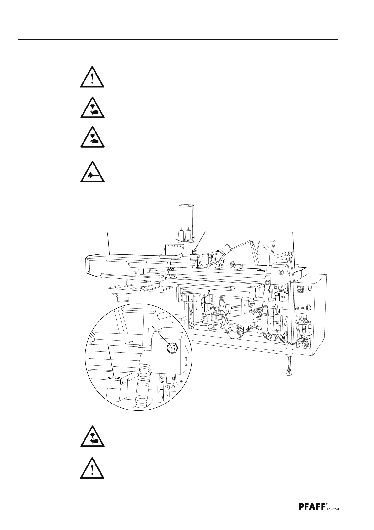
13.04 Servicing position of the sewing head................................................................................. 67
13.05 Adjusting the sewing head ................................................................................................. 69
13.05.01 Adjustment aids ................................................................................................................... 69
13.05.02 Basic position of the machine drive ...................................................................................70
13.05.03 Needle in needle hole centre............................................................................................... 71
13.05.04 Hook shaft bearing and toothed belt tension....................................................................... 72
13.05.05 Hook lubrication .................................................................................................................. 73
13.05.06 Needle rise, hook-to-needle clearance, needle height and bobbin case position finger .......74
13.05.07 Thread check spring and slack thread regulator ................................................................... 75
13.05.08 Bobbin winder...................................................................................................................... 76
13.06 Adjusting the thread trimming device.................................................................................. 77
13.06.01 Preliminary adjustment of the control cam.......................................................................... 77
13.06.02 Adjusting the roller lever ...................................................................................................... 78
13.06.03 Lateral adjustment of the thread catcher............................................................................. 79
13.06.04 Knife position ....................................................................................................................... 80
13.06.05 Front point of reversal of the thread catcher........................................................................ 81
13.06.06 Manual trimming check........................................................................................................ 82
13.06.07 Readjusting the control cam ................................................................................................ 83
13.07 Adjusting the loading table .................................................................................................. 84
13.07.01 Basic setting of the loading table height.............................................................................. 84
13.07.02 Positioning the loading table ................................................................................................ 85
13.07.03 Retraction depth of the loading table...................................................................................86
13.08 Adjusting the sewing head ..................................................................................................87
13.08.01 Height of the sewing head................................................................................................... 87
13.08.02 Side adjustment of the machine head ................................................................................. 88
13.09 Adjusting the cloth plate ...................................................................................................... 89
13.10 Adjusting the positioning tube .............................................................................................90
13.10.01 Pre-setting the positioning tube........................................................................................... 90
13.10.02 Front end position of the positioning tube ........................................................................... 91
13.10.03 Height and location of the positioning tube ......................................................................... 92
13.11 Height of the needles .......................................................................................................... 93
13.12 Adjusting the spreader......................................................................................................... 94
13.13 Adjusting the table extension ..............................................................................................95
13.14 Adjusting the loading clamp................................................................................................. 96
13.14.01 Height of the loading clamp................................................................................................. 96
13.14.02 Position of the loading clamp ............................................................................................... 97
13.15 Adjusting the brushes .......................................................................................................... 98
13.15.01 Adjusting the long brushes .................................................................................................. 98
13.15.02 Adjusting the short brushes................................................................................................. 99
13.16 Adjusting the knife unit ...................................................................................................... 100
13.16.01 Pre-setting the knife unit.................................................................................................... 100
13.16.02 Height of the knife unit .......................................................................................................101
13.16.03 Knife change ...................................................................................................................... 102

Contents
Contents ....................................................................................Chapter - Page
13.17 Adjusting the workholder bar............................................................................................. 103
13.17.01 Zero point of the workholder bar ....................................................................................... 103
13.17.02 Workholder bar stop .......................................................................................................... 104
13.18 Adjusting the pneumatic table pressure ............................................................................ 105
13.19 Adjusting the pressure control device ............................................................................... 106
13.20 Adjusting the stacker ......................................................................................................... 107
13.21 Adjusting the sensor on the stacker clamp........................................................................ 108
13.22 Boot key..............................................................................................................................110
13.23 Service menu......................................................................................................................111
13.23.01 Cold start ............................................................................................................................113
13.23.02 Machine configuration ........................................................................................................114
13.23.03 Loading / updating the operating program..........................................................................115
13.24 Sewing motormenu ............................................................................................................116
13.25 Parameter settings..............................................................................................................117
13.25.01 Selecting and altering parameters. .....................................................................................117
13.25.02 Parameter list......................................................................................................................118
14 Control unit....................................................................................................................... 120
14.01 Basic setting / Diagnosis / Pin assignment ........................................................................ 120
14.01.01 Power unit A30 .................................................................................................................. 120
14.01.02 Basic control unit A20 ........................................................................................................ 122
14.01.03 Sewing drive A22............................................................................................................... 124
14.01.04 Stepping motor drive ......................................................................................................... 125
14.01.05 CAN node A10, A11, A12 ................................................................................................... 126
14.02 Description of the error messages .................................................................................... 128
14.02.01 General errors .................................................................................................................... 128
14.02.02 CAN-Error........................................................................................................................... 130
14.02.03 Stitch generation error ....................................................................................................... 130
14.02.04 Sewing motor error............................................................................................................ 131
14.02.05 Errors – Stepping motor drive ............................................................................................ 132
14.03 List of outputs and inputs .................................................................................................. 133
14.03.01 CAN-Nodes 1 ..................................................................................................................... 133
14.03.02 CAN-Nodes 2 .................................................................................................................... 134
14.03.03 CAN-Nodes 3 .................................................................................................................... 135
14.03.04 Special outputs .................................................................................................................. 136
15 Pneumatic system circuit diagram ................................................................................. 137
16 Circuit diagrams............................................................................................................... 144

Safety
7
1 Safety
1.01 Directives
This machine is constructed in accordance with the European regulations contained in the
conformity and manufacturer’s declarations.
In addition to this Instruction Manual, also observe all generally accepted, statutory and
other regulations and legal requirements and all valid environmental protection regulations!
The regionally valid regulations of the social insurance society for occupational accidents or
other supervisory organizations are to be strictly adhered to!
1.02 General notes on safety
This machine may only be operated by adequately trained operators and only after having●
completely read and understood the Instruction Manual!
All Notes on Safety and Instruction Manuals of the motor manufacturer are to be read be-●
fore operating the machine!
The danger and safety warnings attached to the machine must be observed and must not●
be removed!
This machine may only be used for the purpose for which it is intended and may not be●
operated without its safety devices. All safety regulations relevant to its operation are to
be adhered to.
When exchanging sewing tools (e.g. needle, sewing foot, needle plate etc.), when threa-●
ding the machine, when leaving the machine unattended and during maintenance work,
the machine is to be separated from the power supply by switching off the On/Off switch
or by removing the plug from the mains!
Everyday maintenance work is only to be carried out by appropriately trained personnel!●
The machine must be disconnected from the pneumatic supply network formaintenance●
and repair work on pneumatic equipment! Exceptions are only permitted for adjustments
and for function tests carried out by appropriately trained staff!
Repairs and special maintenance work may only be carried out by qualified service staff●
or appropriately trained personnel!
Work on electrical equipment may only be carried out by appropriately trained personnel!●
Work is not permitted on parts and equipment which are connected to the power supply!●
The only exceptions to this rule are found in the regulations EN 50110.
Modifications and alterations to the machine may only be carried out under observance●
of all the relevant safety regulations!
Only spare parts which have been approved by us are to be used for repairs! We express-●
ly point out that any replacement parts or accessories which are not supplied by us have
not been tested and approved by us. The installation and/or use of any such products can
lead to negative changes in the structural characteristics of the machine. We are not liable
for any damage which may be caused by non-original parts.

Safety
8
1.03 Safety symbols
Danger!
Points to be observed..
Danger of injury for operating and specialist personnel!
Danger: Laser beam!
Caution
Do not operate without finger guard and safety devices.
Before threading, changing bobbin and needle, cleaning
etc. switch off main switch.
Only one person allowed in working area!
During operation only one person is allowed to be in the working area of the
machine!
Do not lean on table!
The mechanical feed system can be damaged by leaning on the loading table.
I
1.04 Important points for the user
This Instruction Manual is an integral part of the machine and must be available to the●
operating personnel at all times.
The Instruction Manual must be read before operating the machine for the first time.●
The operating and specialist personnel is to be instructed as to the safety equipment of●
the machine and regarding safe work methods.
It is the duty of the user to only operate the machine in perfect running order.●
It is the obligation of the user to ensure that none of the safety mechanisms are removed●
or deactivated.
It is the obligation of the user to ensure that only authorized persons operate and work●
on the machine.
Further information can be obtained from your PFAFF agent.

Safety
9
1.05 Operating and specialist personnel
1.05.01 Operating personnel
Operating personnel are persons responsible for the equipping, operating and cleaning of
the machine as well as for taking care of problems arising in the sewing area.
The operating personnel is required to observe the following points and must:
always observe the Notes on Safety in the Instruction Manual!●
never use any working methods which could adversely affect the safety of the machine!●
not wear loose-fitting clothing or jewelery such as chains or rings!●
also ensure that only authorized persons have access to the potentially dangerous area●
around the machine!
always immediately report to the person responsible any changes in the machine which●
may limit its safety!
1.05.02 Specialist personnel
Specialist personnel are persons with a specialist education in the fields of electrics, electro-
nics and mechanics. They are responsible for the lubrication, maintenance, repair and adjust-
ment of the machine.
The specialist personnel is obliged to observe the following points and must:
always observe the Notes on Safety in the Instruction Manual!●
switch off the On/Off switch before carrying out adjustments or repairs, and ensure that●
it cannot be switched on again unintentionally!
wait until the luminous diode on the control box is no longer blinking or on before begin-●
ning adjustment or repair work.
never work on parts which are still connected to the power supply! Exceptions are explai-●
ned in the regulations EN 50110.
replace the protective coverings and close the electrical control box afer all repairs or●
maintenance work!

Safety
10
1.06 Danger
A working area of 1 meter is to be kept free both in front of and behind the ma-
chine while it is in operation so that it is always easily accessible.
During sewing do not place hands in the working area of the machine!
Danger of injury from the sewing head needles and loading equipment!
Never leave objects on the table while adjusting the machine settings!
Objects can become trapped or be slung away! Danger of injury!
Do not look into laser beam either with or without optical equipment!
Danger of injury to the retina from the directed light!
Only operate the machine with covers 1 and 2 closed!
Danger of injury from moving machine parts!
The emergency-off button 3 is used to stop the machine immediately in
case of emergencies.
Fig. 1 - 01
1
23
4
5

Proper use
11
2 Proper use
The PFAFF 3519-4/01 is an automatic sewing unit for sewing single- or double-pointed jacket
breast darts.
Any and all uses of this machine which have not been approved of by the
manufacturer are considered to be inappropriate! The manufacturer cannot be
held liable for any damage caused by the inappropriate use of the machine!
The appropriate use of the machine includes the observance of all operational,
adjustment, maintenance and repair measures required by the manufacturer!

Specifications
12
3 Specifications▲
Stitch type: .........................................................................................................301 (lockstitch)
Needle system:.................................................................................................................... 134
Needle size in 1/100 mm: ............................................................................................. 80 - 100
Stitch length:..........................................................................................................0,5 - 3,0 mm
Max. sewing speed:...................................................................................................4300 spm
Stitch length start tacks: ...........................Standard stitch length or half standard stitch length
Number of stitches for start tacks: .................................................................................... 1 – 9
Stitch length start/end condensed stitches:................................................................1 – 3 mm
Number of stitches start/end condensed stitches: ........................................................... 1 – 9
Sewing area size
Dart depth:.................................................................................................................5 - 12 mm
Dart length: ............................................................................................................80 - 395 mm
Max. material thickness for sewing: .................................................................................4 mm
Machine dimensions:
Length:..........................................................................................................approx. 2.800 mm
Width: .............................................................................................................1.200 - 1.800 mm
Height: .......................................................................................................... approx. 1400 mm
Weight: ...............................................................................................................approx. 695 kg
Electrical data
Power supply:: ..................................................................................... 230 V ± 10 %, 50/60 Hz
Max. output: .....................................................................................................................3 kVA
Fuse protection: ...................................................................................................1 x 16 A, inert
Working air pressure:......................................................................................................... 6 bar
Air consumption:...........................................................................................ca. 25 l/work cycle
Noise data:
Noise emission level at workplace with a sewing speed of 4300 spm: ...........LpA = 74 dB(A) ■
(Noise measurement in accordance with DIN 45 635-48-B-1, ISO 11204, ISO 3744, ISO 4871)
▲Subject to alterations
■K
pA = 2,5 dB

13
Disposal of Machine
4 Disposal of Machine
Proper disposal of the machine is the responsibility of the customer.●
The materials used for the machine are steel, aluminium, brass and various plastic●
materials. The electrical equipment comprises plastic materials and copper.
The machine is to be disposed of according to the locally valid pollution control regula-ti-●
ons; if necessary, a specialist ist to be commissioned.
Care must be taken that parts soiled with lubricants are disposed of separately
according to the locally valid pollution control regulations!

Transportation, packing and storage
14
5 Transportation, packing and storage
5.01 Transportation to customer‘s premises
The machines are delivered completely packed.
5.02 Transportation inside the customer‘s premises
The manufacturer cannot be made liable for transportation inside the customer‘s premises
nor to other operating locations. It must be ensured that the machines are only transported
in an upright position.
5.03 Disposal of packing materials
The packing materials of this machine comprise paper, cardboard and VCE fibre. Proper dis-
posal of the packing material is the responsibility of the customer.
5.04 Storage
If the machine is not in use, it can be stored as it is for a period of up to six months, but It
should be protected against dust and moisture.
If the machine is stored for longer periods, the individual parts, especially the surfaces of
moving parts, must be protected against corrosion, e.g. by a film of oil.

Explanation of symbols
15
6 Explanation of symbols
In this instruction manual, work to be carried out or important information is accentuated by
symbols. These symbols have the following meanings:
Note, information
Cleaning, care
Lubrication
Maintenance, repairs, adjustment, service work
(only to be carried out by technical staff)

Controls
16
Fig. 7 - 01
7 Controls
7.01 On/off switch
Switch the machine on or off by turning●
main switch 1.
1
Fig. 7 - 02
7.02 Machine control unit button
After the power supply has been swit-●
ched on with the main switch, see Chap-
ter 7.01. Main Switch, press button 1 to
switch on the machine control unit and
make the machine ready for operation.
When the machine is ready for
operation, button 1 lights up.
1

Controls
17
7.03 Switch for the extractor fan (optional)
The extractor fan integrated in
the machine is only required, if
there is no vacuum network at
the machine’s location.
Press key●1 to switch on the extractor
fan.
Press key●2 to switch off the extractor
fan.
Fig. 7 - 03
1
2
7.04 Emergency-off button
In the event of emergencies, press the●
emergency-off button 1 to stop the ma-
chine immediately.
The emergency-off button 1
may only be pressed in cases
of emergency!
After pulling up the pressed
EMERGENCY-OFF button 1, the
machine can be switched back
on again with the button on the
machine control unit, see Chap-
ter 7.02 Machine control unit
button.
Fig. 7 - 04
1

Controls
18
Fig. 7 - 05
7.05 Control panel
The current operating conditions are dis-
played on control panel 1. Operation takes
place in a constant dialogue between the
control unit and the operator. For this pur-
pose, depending on the operating conditi-
on of the machine, different symbols and/or
texts are displayed. If the symbols or texts
are framed, these show functions which can
be selected by pressing the appropriate po-
sition on the monitor. By pressing the cor-
responding function this is carried out or
switched on or off immediately, or a further
menu appears, e.g. for entering a value. Ac-
tivated functions are shown with inverted
symbols. Unframed symbols or texts are
only used for display purposes and cannot
be selected by pressing.
To read sewing programs or install machine software, use the sd-card 2 in the control
panel.
1
2 GB
max.
2
7.06 Pedal
The suction air for the loading table and●
the positioning tube are switched on and
off by operating pedal 1.
Fig. 7 - 06
1

Controls
19
7.07 Start keys
By pressing both start keys●1 at the same time, the sewing cycle is started.
After the sewing cycle has been completed, the illuminated start keys 1 indica-
te that the next sewing cycle can be started.
If the threading aid is activated, by pressing both start keys●1 at the same time, the loa-
ding table is moved forward and the hook area of the sewing head becomes accessible.
Fig. 7 - 07
1
1

Installation and commissioning
20
8 Installation and commissioning
This machine may only be installed and commissioned by qualified specialists!
All relevant safety regulations are to be adhered to!
8.01 Installation
Suitable connections for the supply of electricity and compressed air must be available at
the machine site, see Chapter 3 Specifications.
It must also be ensured that the standing surface of the machine site is firm and horizontal,
and that sufficient lighting is provided.
8.01.01 Aligning the machine
Loosen nut●1 and turn foot 2 so that the machine stands horizontally.
Tighten nut●1.
The alignment of the bottom frame tubes can be checked with the aid of a
spirit level.
Fig. 8 - 01
1
2
Table of contents
Other Pfaff Sewing Machine manuals

Pfaff
Pfaff varimatic 6089 User manual

Pfaff
Pfaff Series 580 Owner's manual

Pfaff
Pfaff Creative 7550 User manual

Pfaff
Pfaff coverlock 4862 User manual

Pfaff
Pfaff Creative 7530 User manual

Pfaff
Pfaff Creative Vision Manual

Pfaff
Pfaff 3119 User manual

Pfaff
Pfaff 8330 User manual

Pfaff
Pfaff hobbylock 4752 User manual

Pfaff
Pfaff hobbylock 799 User manual

Pfaff
Pfaff 900/51 User manual

Pfaff
Pfaff select 1540 User manual

Pfaff
Pfaff creative 1475CD User manual

Pfaff
Pfaff 141 User manual

Pfaff
Pfaff 238 User manual

Pfaff
Pfaff 294 User manual

Pfaff
Pfaff Quilt Expressions 4.0 User manual

Pfaff
Pfaff hobbymatic 933 User manual

Pfaff
Pfaff 3819 series User manual

Pfaff
Pfaff 3574-2/02 User manual