Pfaff 1180 U Series Owner's manual

Supplement to the instruction
manual and parts list for the
series 1180, 938 U
SRP
296-12-18 748/002
engl. 01.2007

Reprinting, copying or translation of PFAFF instruction manuals, whether in whole or in
part, is not permitted without our prior permission and not without written indication of the
source.
PFAFF Industrie Maschinen AG
Postfach 3020
D-67653 Kaiserslautern
Königstr. 154
D-67655 Kaiserslautern

Index
Contents ..................................................................................Page
1 Proper use ..........................................................................................................................4
2 Controls ................................................................................................................................5
2.01 Knee switch .......................................................................................................................... 5
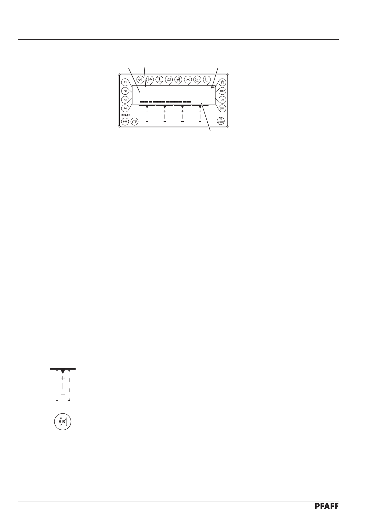
2.02 Control panel .......................................................................................................................... 6
2.02.01 Screen displays ...................................................................................................................... 6
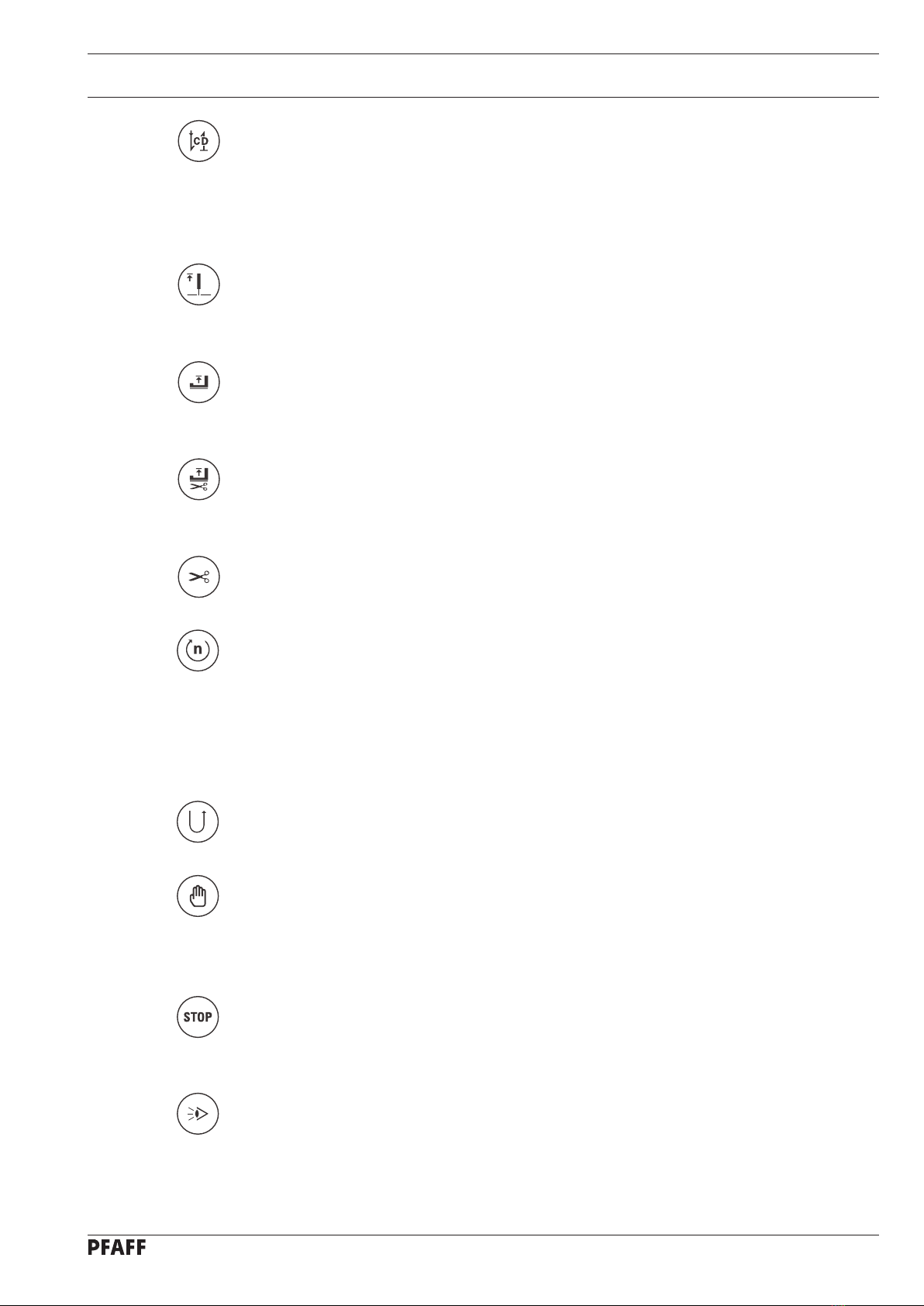
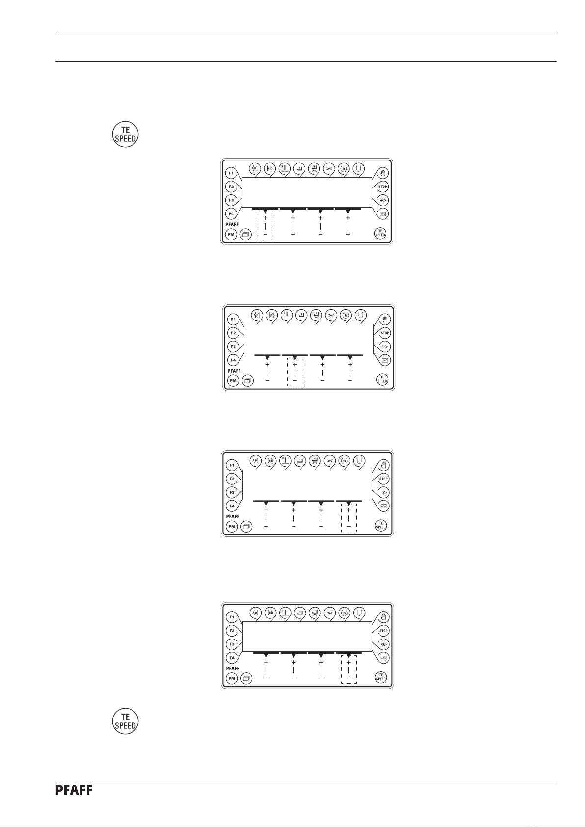
2.02.02 Function keys ......................................................................................................................... 6
2.02.03 Selecting and altering parameters ......................................................................................... 9
2.02.04 Selecting the user level ........................................................................................................ 10
3 Commissioning .................................................................................................................. 11
3.01 Basic position of the machine drive ..................................................................................... 11
3.02 Testing the function of the start inhibitor ............................................................................. 12
4 Setting up ........................................................................................................................... 13
4.01 Entering the maximum speed ............................................................................................. 13
4.02 Setting the presser foot pressure ........................................................................................ 13
4.03 Entering the start and end backtacks ................................................................................... 14
4.04 Setting the stitch counting function for the bobbin thread control ...................................... 15
5 Sewing ................................................................................................................................ 16
5.01 Manual sewing .................................................................................................................... 16
5.02 Programmed sewing ............................................................................................................ 17
5.03 Error messages .................................................................................................................... 18
6 Parameter Settings ............................................................................................................. 19
7 Internet update of the machine software ......................................................................... 20
8 Reset / Cold start ................................................................................................................ 21
9 Parts list ............................................................................................................................. 22
10 Circuit diagrams .................................................................................................................23

Proper use
4
1 Proper use
The SRP system uses a linear motor to adjust the presser foot pressure to the actual sewing
speed or workpiece. In addition the presser foot clearance can be adjusted individually.
The adjustments are made by altering parameter values, see Chapter 2.02.03 Selecting/
altering parameters.
Any and all uses of this machine which have not been approved of by the
manufacturer are considered to be inappropriate! The manufacturer cannot be
held liable for any damage caused by the inappropriate use of the machine!
The appropriate use of the machine includes the observance of all operational,
adjustment, maintenance and repair measures required by the manufacturer!

Controls
5
2 Controls
2.01 Knee switch
By operating knee switch 1, the presser
foot can be raised when sewing is inter-
rupted.
●
Fig. 2 - 01
1

Controls
6
2.02 Control panel
The control panel consists of display 1 and the function keys described below. The display
1 consists of a two-line alpha-numerical LCD display with 16 symbols per line. The texts 3
show the respective status of the function keys and the operating status of the machine.
The control panels switches on all LCD-segments and the horn automatically for a short time
during the power-on phase, after which the lettering PFAFF appears on the display, until the
higher-ranking control unit sends commands to the control panel.
2.02.01 Screen displays
Activated functions are displayed with a triangular marking 2 below or next to the respec-
tive function key.
In the sewing mode all relevant sewing data is displayed and these can be changed di-
rectly, depending on the status of the machine, see also Chapter 5 Sewing.
During the parameter input the selected parameter number with the corresponding value
is displayed, see Chapter 2.02.03 Selecting/changing parameters.
2.02.02 Function keys
The function keys described below are used basically to switch machine functions on and
off.
If a corresponding value has to be set for the activated function, this is carried out with the
corresponding +/- key. By pressing and holding the corresponding +/- key, the appropriate
numerical value 4 is changed slowly to begin with. If the corresponding +/- key is held down
longer, the values change more quickly.
Start backtacks
If this key is pressed, the backtacks at the beginning of the seam (start backtacks) are
switched on or off. The number of forward stitches (A) or reverse stitches (B) for the start
backtacks can be changed by pressing the +/- key underneath. To convert from double
backtack to single backtack set the corresponding number of stitches at zero.
●
●
●
●
Speed
4000 SRP
30%
132
4

Controls
7
End backtacks
If this key is pressed, the backtacks at the end of the seam (end backtacks) are switched
on or off. The number of reverse stitches (C) or forward stitches (D) can be changed by
pressing the +/- key underneath. To convert from double backtack to single backtack set
the corresponding number of stitches at zero.
Needle position
If this key is pressed the corresponding function is switched on or off. When the function
is switched on, the needle positions at t.d.c. after sewing stops.
Foot position after stop
If this key is pressed the corresponding function is switched on or off. When the function
is switched on, the presser foot is raised after sewing stops.
Foot position after trimming
If this key is pressed the corresponding function is switched on or off. When the function
is switched on, the presser foot is raised after thread trimming.
Thread trimmer
If this key is pressed the thread trimming function is switched on or off.
Speed (only in programmed sewing)
If this key is pressed the corresponding function is switched on or off. In the seam pro-
gram the speed is not dependent on the pedal. When the function is switched on, the
speed cannot be adjusted by pedal. Sewing can only be carried out at the set maximum
speed.
If the function is switched off, the speed up to maximum speed is adjusted by the pedal.
Reverse sewing
If this key is pressed the reverse sewing function is switched on or off.
Manual seam (only in programmed sewing)
If this key is pressed the machine switches to manual sewing. When the function is swit-
ched on, the move to the next seam section is not carried out by stitch counting or sen-
sor, but manually with the use of the pedal (position "-2").
Stop
If this key is pressed the corresponding function is switched on or off. When the function
is switched on, the machine stops automatically at the end of a seam section.
Sensor
In manual sewing the number of compensating stitches from the point where the photo-
cell is light to the end of the seam can be set under parameter 111, and in programmed
sewing directly.
●
●
●
●
●
●
●
●
●
●
●

Controls
8
Stitch counting
If this key is pressed the corresponding function is switched on or off. The value for the
compensating stitches can be changed immediately with the corresponding +/- key.
When the function is switched on, the machine moves to the next seam section after se-
wing the number of stitches entered.
TE/Speed
In the programmed sewing mode, the number of stitches is entered by stitching them
off.
If this key is pressed once, the machine changes to parameter input.
If this key is pressed twice (within 5 seconds) the machine changes to stitch input.
Scrolling
If this key is pressed in the programmed sewing mode, the machine scrolls through the
input menus on the display.
PM
If this key is pressed the programmed sewing function is switched on or off. When the
function is switched on, the letters "PM" appear on the display of the control panel. The
parameters related to the program are shown in the alpha-numerical part of the display.
F1
No function assigned
F2
No function assigned
F3
No function assigned
F4
No function assigned
●
●
●
●
●
●
●
●
●
●

Controls
9
2.02.03 Selecting and altering parameters
Switch on the machine.
Press the TE/Speed key to call up the parameter input function.
●
●
TE
No
200
By pressing the corresponding +/- key select the desired parameter group, e.g. "600".●
TE
No
600
By pressing the corresponding +/- key select the desired parameter, e.g. "660" for the
bobbin thread monitoring function.
●
By pressing the corresponding +/- key set the desired value for the parameter selected,
e.g. "2" for the "bobbin rest thread counter on" function..
●
TE
No VAL
660 1
TE
No VAL
660 2
Press the TE/Speed key to take over the value and change to the sewing mode.●
No
No
VAL

Controls
10
2.02.04 Selecting the user level
Switch on the machine.
Press the TE/Speed key to call up the parameter input function.
●
●
TE
No
101
By pressing the corresponding +/- key select the parameter group "700".●
By pressing the corresponding +/- key select the parameter "798".●
TE
No
A 798 0
TE
No VAL
B 798 1
By pressing the corresponding +/- key select the desired user level:
"0" = operator level A
"1" = technician level B
"11" = service level C
The respective level is displayed on the screen. (see arrow)
Press the TE/Speed key to take over the value and change to the sewing mode.
●
●
No
VAL
No

11
Commissioning
3 Commissioning
3.01 Basic position of the machine drive
Switch on the machine.●
Press the TE/Speed key to call up the parameter input function.
Select the technician level B (value "1") with parameter "798", see Chapter 2.02.04
Selecting the user level.
●
●
By pressing the corresponding +/- key select the parameter group "700".●
Sew a stitch by operating the pedal.
Turn the balance wheel in the direction of sewing until the needle point is level with the
top edge of the needle plate.
Press the TE/Speed key to take over the setting and to conclude the input.
●
●
●
No
Speed
4000 SRP
30%
TE
No VAL
B 798 1
TE
No
B 700 0

Commissioning
12
3.02 Testing the function of the start inhibitor
ERROR
9
PRESS TE-SPEED
Switch the machine on at the main switch and tilt back the sewing head.
The error message "ERROR 9" must appear on the control panel.
If the message does not appear, check the setting of the safety switch
(in the machine instruction manual).
Set the sewing head upright again and acknowledge the error message by pressing the
TE/Speed key. The machine is ready for operation again.
●
●
●

Setting up
13
4 Setting up
4.01 Entering the maximum speed
Switch on the machine.●
Enter the maximum speed by pressing the corresponding +/- key.●
4.02 Setting the presser foot pressure
The presser foot pressure is adjusted with the sewing speed. The greater the sewing speed,
the higher the pressure foot pressure. By altering the percent increase of the presser foot
pressure, the increase of the presser foot pressure can be influenced by an increased sew-
ing speed. The current pressure foot pressure can be seen on the bar graph display.
Switch on the machine.
Set the desired percent increase of the presser foot pressure by pressing the correspon-
ding +/- key.
●
●
Speed
4000 SRP
30%
Speed
4000 SRP
30%

Setting up
14
4.03 Entering the start and end backtacks
Switch on the machine.
Select the manual sewing mode by pressing the "PM" key.
Press the TE/Speed key twice to select the input menu for start and end backtacks.
In the programmed sewing mode it is possible to call up the input menu for
start and end backtacks by pressing the scroll key, see Chapter 5.02 Program-
med sewing.
●
●
●
By pressing the corresponding +/- key select the desired value for the number of forward
stitches (A) of the start backtack.
By pressing the corresponding +/- key select the desired value for the number of reverse
stitches (B) of the start backtack.
By pressing the corresponding +/- key select the desired value for the number of reverse
stitches (C) of the end backtack.
By pressing the corresponding +/- key select the desired value for the number of forward
stitches (D) of the end backtack.
●
●
●
●
A
B
C
D
2x
PM
A B C C
3 3 3 3

Setting up
15
4.04 Setting the stitch counting function for the bobbin thread control
Switch on the machine.
Press the TE/Speed key to call up the parameter input function.
●
●
TE
No VAL
A 101 ON
By pressing the corresponding +/- key select the parameter "760".●
Press the corresponding +/- key to set the number of remaining stitches, which can still be
sewn after recognition by the bobbin thread control function.
The selected value is multiplied by 10* or 200** and the result is the number of stitches.
Example display 5 x 200** = 1000 stitches. The setting depends among other things on the
thread strength.
If the TE/Speed key is pressed, the value is taken over and the machine changes into the
sewing mode.
The bobbin thread rest counter can only be used, if parameter "660" is set at va-
lue "1" or "2".
* If for parameter 660 the value is "1", the multiplier is 10
** If for parameter 660 the value is "2", the multiplier is 200
●
TE
No VAL
A 760 5
VAL
No
2x

Sewing
16
5 Sewing
In the sewing mode all relevant adjustments for the sewing operation are shown on the dis-
play and can be altered directly. Functions can be switched on and off by pressing the key.
In this mode a difference is made between manual sewing and programmed sewing. To
change from manual to programmed sewing, press the PM key. In programmed sewing the
text "PM" appears on the display.
5.01 Manual sewing
After the machine has been switched on, the max. speed and presser foot pressure can be
adjusted with the corresponding +/- keys.
Speed
4000 SRP
30%
Further functions in manual sewing, also see Chapter 2.02.02Function keys:
Start backtacks on/off Presser foot raised after
thread trimming on/off
End backtacks on/off Thread trimming on/off
Needle position raised on/off Sensor on/off
Presser foot raised on/off

17
Sewing
5.02 Programmed sewing
In the programmed sewing mode 99 programs, each with 9 seam sections and 999 stitches,
can be programmed.
The fixed programs are used for the quick and easy production of seams with different
numbers of stitches. The pedal setting "0" is used to switch to the next seam section.
After the machine has been switched on and the programmed sewing mode has been
selected with the PM key, the display appears for selecting the program number, seam
section and number of stitches.
With the scroll key other menus can be selected for entering the values for start and end
backtacks and the maximum speed in the corresponding seam section.
PM
1 1 13
current
program number
current seam segment number of stitches
PM
1000 5 0
speed in current
seam segment
number of seam segments
program number
of linked program
Further functions in programmed sewing, also see Chapter 2.02.02 Function keys:
Start backtacks on/off Seam section speed on/off
End backtacks on/off Reverse sewing direction on/
off
Needle position raised on/off Manual sewing on/off
Presser foot raised on/off Stop on/off
Presser foot raised after
thread trimming on/off Sensor on/off
Thread trimming on/off Stitch count on/off

Sewing
18
5.03 Error messages
If a fault occurs, the text "ERROR" appears on the display, together with an error code and
short instructions. An error message is caused by incorrect settings, faulty elements or
seam programs as well as by overload conditions.
ERROR
9
PRESS TE-SPEED
Correct the error.
Acknowledge error correction by pressing the TE/Speed key.
●
●

Parameter Settings
19
The standard values listed in the table are basic settings, which can be altered if
necessary.
For more displays and information see the motor instruction manual.
6 Parameter Settings
Group
Parameter
Description
Access level
Adjustment
range
Standard value
2251 Presser foot clearance when raised
by pedal (pedal position –2)
B, C 0 - 255 160
252 Presser foot clearance when raised
by knee switch
B, C 0 - 255 150
256 Min. presser foot pressure during sewing B, C 0 - 32 10
258 Machine feed type
1 = needle feed, 0 = bottom feed
B, C 0 - 1 0
287 Presser foot clearance when raised
by pedal (pedal position –1)
B, C 0 - 255 150
288 Presser foot holding pressure while the
M/C is stoped
B, C 0 - 255 80
6607 Maximum speed B, C 300 - 5500 4000
660 Bobbin thread monitoring
0 = off
1 = by sensor (-926/06)
2 = by stitch counting
B, C 0 - 2 1180
= 1
938 U
= 0
7700 Needle position 0
(needle reference position
B, C 0 - 255 *
702 Needle position 1 (needle lowered) B, C 0 - 255 90
703 Needle position 2 (take-up lever raised) B, C 0 - 255 236
760 Multiplier for the fixed value (200) for
stitch count
A,B, C 0 - 250 5
799 Selected machine class C 1 - 2 1
8800 Rotating direction of the motor C 0 - 1 0
9985 Switch on angle for thread trapper B,C 0 - 255 67
986 Switch off angle for thread trapper B,C 0 - 255 206
989 Thread trapper at beginning of seam
1 = yes, 0 = no
B,C 0 - 2 0
* Adjustment see Chapter 3.01 Basic position of the machine drive unit.

Software-Update
20
7 Internet update of the machine software
The machine software can be updated with PFAFF flash programming. For this purpose the
PFP boot program and the appropriate control software for the machine type must be in-
stalled on a PC. To transfer the data to the machine, the PC and the machine control unit
must be connected with an appropriate null modem cable (part no. 91-291 998-91).
The PFP boot program and the control software of the machine type
can be downloaded from the PFAFF-homepage using the following path:
www.pfaff-industrial.com/pfaff/de/service/downloads
To update the machine software carry out the following steps:
While the machine software is being updated, no setting up, maintenance or
adjustment work may be carried out on the machine!
Switch off the machine.
Connect the PC (serial interface or appropriate USB-adapter) and the machine control unit
(RS232).
Switch on the PC and start the PFP boot program.
Select the machine type.
Press the "programming" button.
An auxiliary program (Quickloader) is started.
Switch on the machine within 60 seconds.
The software update is carried out, the updating status is shown on the bar display.
After the update has been completed, the message "Software updated successfully
completed" appears.
If this message does not appear, the entire procedure must be repeated!
The operational reliability of the machine is not restored until the programming
has been carried out successfully and without errors.
Switch off the machine, end the quickloader and PFP-boot program.
End the connection between the PC and the machine control unit.
Switch on the machine.
A plausibility control is carried out and, if necessary, a cold start.
More information and assistance is at your disposal in the file "PFPHILFE.TXT",
which can be called up from the PFP boot program by pressing the "help"
button.
●
●
●
●
●
●
●
●
●
●
●
●
This manual suits for next models
1
Table of contents
Other Pfaff Sewing Machine manuals

Pfaff
Pfaff 571 User manual

Pfaff
Pfaff powerquilter 16.0 User manual

Pfaff
Pfaff 1080S User manual

Pfaff
Pfaff perfomance 2054 User manual

Pfaff
Pfaff 461 User manual

Pfaff
Pfaff COVERLOCK 3.0 - User manual

Pfaff
Pfaff 3801-3/07 User manual

Pfaff
Pfaff select 1520 User manual

Pfaff
Pfaff hobbylock 795 User manual

Pfaff
Pfaff select 150 User manual
Popular Sewing Machine manuals by other brands

Atlanta Attachment Company
Atlanta Attachment Company 1347D Technical Manual & Parts Lists

Happy
Happy HK634020XB Maintenance manual

Singer
Singer 15K91 Illustrated parts list

Singer
Singer 247-1 Instructions for using and adjusting

HIGHLEAD
HIGHLEAD GC0318-1A Instruction manual parts catalog

Singer
Singer 240K12 instructions