Pfaff 3538-20/02 Guide

This adjustment manual applies to machines from the
following serial numbers onwards:
# 2 804 345
3538
296-12-19 293/002
Adjustment manual engl. 08.18
ADJUSTMENT MANUAL
-20/02
-30/02

Reprinting, reproduction and/or translation of PFAFF instruction manuals (including parts
thereof) is only permitted with our prior agreement and citation of the source.
PFAFF Industriesysteme
und Maschinen GmbH
Hans-Geiger-Str. 12 - IG Nord
D-67661 Kaiserslautern

Table of Contents
Contents ..................................................................................................Page
13 Adjustment ....................................................................................................4
13.01 Notes on adjustment ............................................................................................................. 4
13.02 Tools, gauges and other accessories .................................................................................... 4
13.03 Abbreviations ......................................................................................................................... 4
13.04 Explanation of symbols.......................................................................................................... 4
13.05 Adjusting basic machine ........................................................................................................ 5
13.05.01 Needle height (pre-calibrating) ............................................................................................... 5
13.05.02 Hook driving eccentric (pre-calibrating).................................................................................. 6
13.05.03 Feed lifting eccentric ............................................................................................................. 7
13.05.04 Spreader driving eccentric ..................................................................................................... 8
13.05.05 Feed driving eccentric and drive for needle bar frame .......................................................... 9
13.05.06 Feed dog position ................................................................................................................ 10
13.05.07 Feed dog height................................................................................................................... 11
13.05.08 Needle position to needle hole ............................................................................................ 12
13.05.09 Hook position crossways to sewing direction ..................................................................... 13
13.05.10 Readjusting hook position in sewing direction / hook eccentric .......................................... 14
13.05.11 Readjusting needle height ................................................................................................... 15
13.05.12 Spreader position in sewing direction.................................................................................. 16
13.05.13 Spreader position crossways to sewing direction ............................................................... 17
13.05.14 Needle guard and thread-loop support ................................................................................ 18
13.05.15 Compensation weight.......................................................................................................... 19
13.05.16 Feed difference.................................................................................................................... 20
13.05.17 Clearance between presser foot and needle plate .............................................................. 21
13.05.18 Needle thread regulation and take-up lever guard ............................................................... 22
13.05.19 Looper thread regulation...................................................................................................... 23
13.05.20 Stitch length limitation ......................................................................................................... 24
13.05.21 Adjusting workpiece infeed and stop ................................................................................. 25
13.05.22 Sensors, settings ................................................................................................................ 26
13.05.23 Adjusting feed band on right, belt tension and belt height ................................................. 27
13.05.24 Adjusting feed band on left, belt tension and belt height ................................................... 28
13.05.25 Chain cutter, settings .......................................................................................................... 29
13.05.26 Feed mechanism: accepting pocket .................................................................................... 30
13.05.27 Feed mechanism: taking over pocket.................................................................................. 31
13.05.28 Adjusting protective cover on stacker and sensor .............................................................. 32
13.05.29 Round table, lift adjustment ................................................................................................ 33
13.05.30 Traversing unit .................................................................................................................... 34
14 Circuit Diagrams ................................................................................................................ 35
14.01 Circuit diagrams ................................................................................................................... 35

Adjustment
4
13 Adjustment
Observe and comply with all instructions in the operating manual’s chapter 1
Safety! In particular make sure that all safety covers are installed again correct-
ly after making adjustments, see chapter 1.06 Operating manual hazard infor-
mation!
Unless otherwise stated, the machine must be disconnected from the power
supply before all adjustment work!
Risk of injury due to accidental machine start-up!
13.01 Notes on adjustment
All adjustments in this manual are based on a fully assembled machine and may only be car-
ried out by technical staff trained for this purpose. Machine covers, which have to be re-
moved and replaced to carry out checks and adjustments, are not mentioned in the text.
The order of the following chapters corresponds to the most logical work sequence for ma-
chines that have to be completely adjusted. Both the preceding and following chapters must
be observed if only specific individual work steps are carried out. Screws and nuts indicated
in brackets ( ) are fastenings for machine parts, which must be loosened before any adjust-
ment and tightened again afterwards.
13.02 Tools, gauges and other accessories
O1set of screwdrivers with knife widths of 2to 10 mm
O1set of wrenches with jaw widths from 6to 22 mm
O1set of Allen keys of 1.5to 6mm
O1metal ruler (order no. 08-880 218-00
ONeedle rise gauge (order no. 61-111 600-01)
OScrew clamp (order no. 61-111 600-35)
OAdjustment pin (order no. 61-111 643-55)
ONeedles, system (62-57)
OThread and testing material
13.03 Abbreviations
t.d.c. = top dead centre
b.d.c. = bottom dead centre
13.04 Explanation of symbols
Activities to be performed or important information in this adjustment manual are empha-
sised by symbols. The symbols used have the following meaning:
Note, information
Maintenance, repairs, adjustment, service work
(only to be carried out by technical staff)

Adjustment
5
13.05 Adjusting basic machine
13.05.01 Needle height (pre-calibrating)
Rule
When the needle bar is in t.d.c., the clearance between the needle point and needle
plate should be approx. 12 mm with a needle bar stroke of 36 mm.
OAdjust the needle bar 1(screw 2) without twisting according to the rule.
Fig. 13 - 01
2
1
12 mm

Adjustment
6
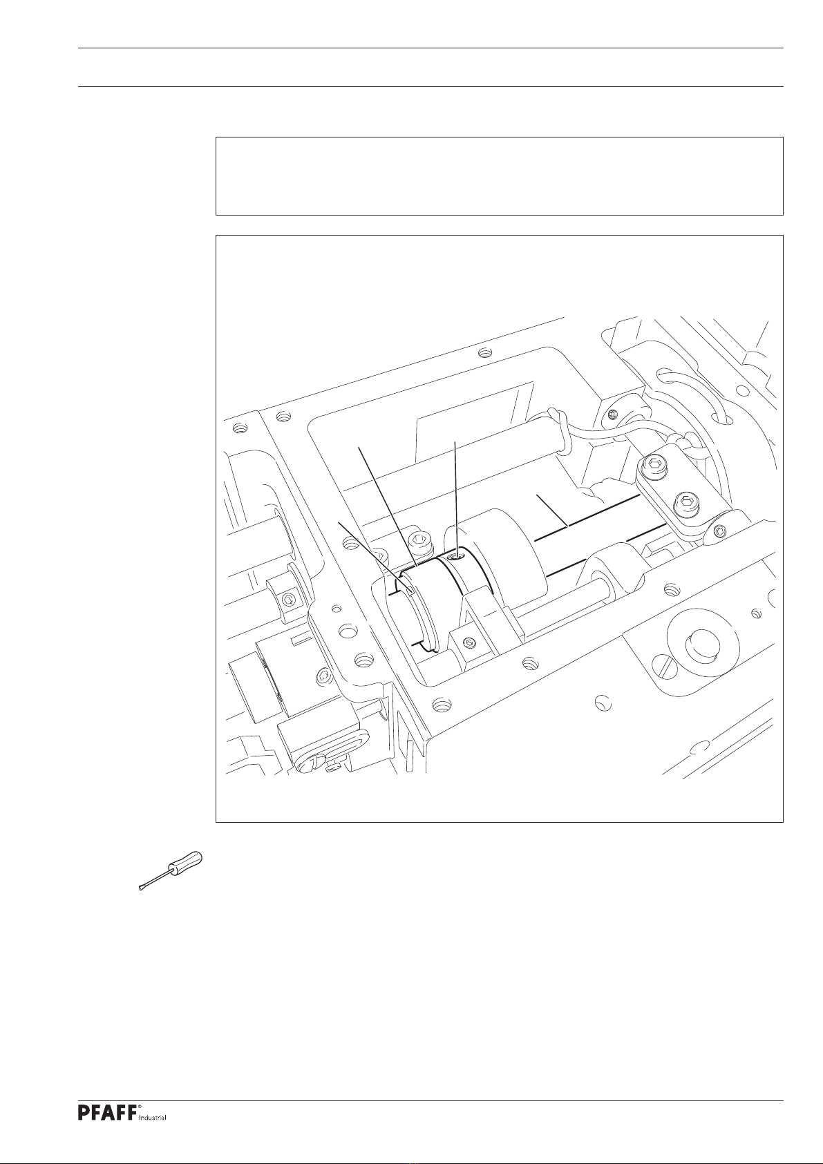
13.05.02 Hook driving eccentric (pre-calibrating)
Rule
When the needle bar is in b.d.c., the round side of the adjustment pin 1
(order no. 61-111 643-55) should engage in the groove 5.
OInsert the adjustment pin 1in the hole 2.
OTurn the eccentric 3(screws 4) according to the rule.
ORemove the adjustment pin 1.
Fig. 13 - 02
1
3
2
3
4
5
Adjustment
7
13.05.03 Feed lifting eccentric
Rule
When the needle bar is in b.d.c., the groove 3should be positioned vertically above the
shaft 4.
OTurn the eccentric 1(screws 2) according to the rule.
Fig. 13 - 03
12
4
3

Adjustment
8
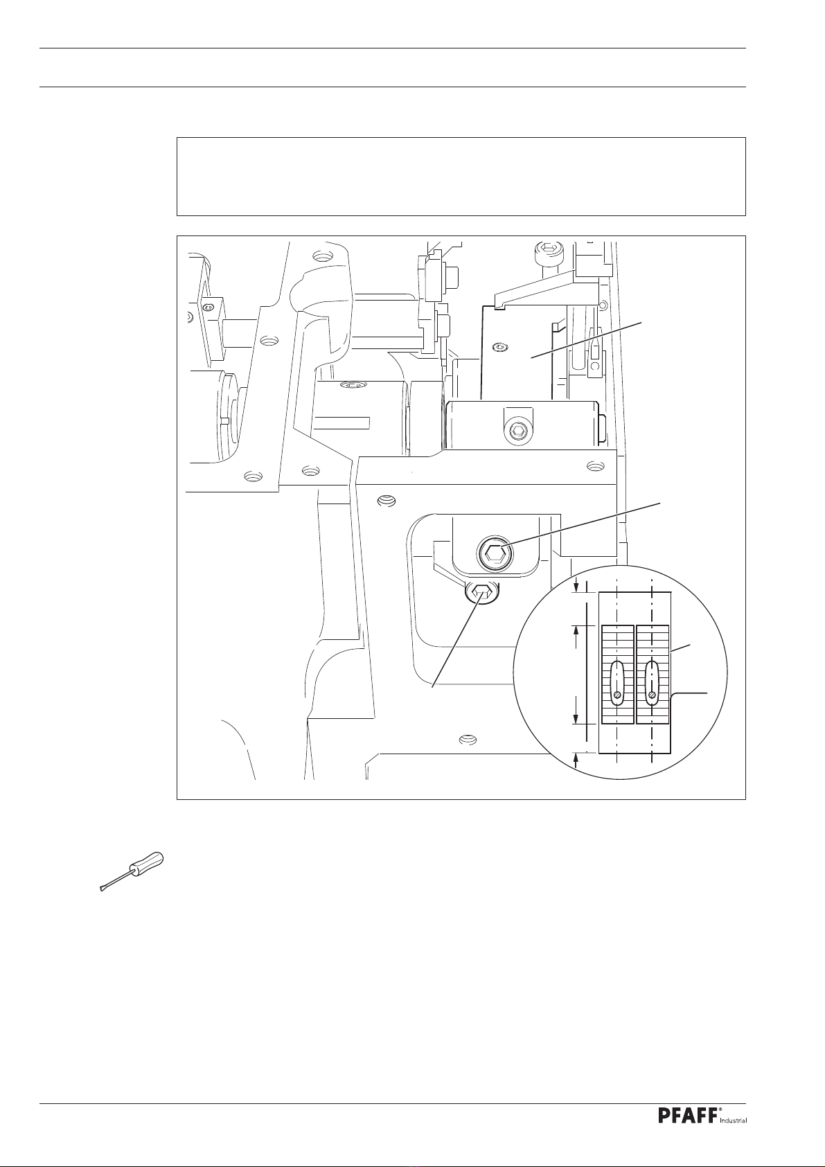
13.05.04 Spreader driving eccentric
Rule
1. When the needle bar is positioned 1 mm after b.d.c., the groove 5of the eccentric 1
should be positioned vertically above the shaft 3.
2. The spreader holder 4should move 6mm.
OTurn the eccentric 1(screws 2) according to rule 1or adjust (axially) according to rule 2.
Fig. 13 - 04
1
2
3
5
3
6 mm
4

Adjustment
9
13.05.05 Feed driving eccentric and drive to needle bar frame
Rule
When the needle bar is in b.d.c.,
1. the groove 7of the eccentric 1should be positioned vertically above the shaft 5and
2. the crank 3should be positioned vertically to the shaft 6
OTurn the eccentric 1(screws 2) according to rule 1.
OTurn the crank 3(screw 4) according to rule 2.
Fig. 13 - 05
3
6
4
2
7
5
1
Adjustment
10
13.05.06 Feed dog position
Rule
The feed dog 4should move laterally and longitudinally in the centre of the needle plate
recess at maximum stitch length.
OAlign the attachment 1(screws 2and 3) according to the rule.
Fig. 13 - 06
1
2
3
4
=
=
This manual suits for next models
1
Table of contents
Other Pfaff Sewing Machine manuals

Pfaff
Pfaff powerquilter 1600 User manual

Pfaff
Pfaff 918 User manual

Pfaff
Pfaff 130-6 User manual

Pfaff
Pfaff Creative Vision User manual

Pfaff
Pfaff 118 User manual

Pfaff
Pfaff Creative Performance User manual

Pfaff
Pfaff 335 User manual

Pfaff
Pfaff 3108-1/1306 User manual

Pfaff
Pfaff Creative 2140 User manual

Pfaff
Pfaff 487 User manual

Pfaff
Pfaff 481 User manual

Pfaff
Pfaff hobbymatic 917 User manual

Pfaff
Pfaff 140S User manual

Pfaff
Pfaff C1100 Pro User manual

Pfaff
Pfaff electronic 6250 User manual

Pfaff
Pfaff 1193 User manual

Pfaff
Pfaff coverlock 4852 User manual

Pfaff
Pfaff 3519-5/01 User manual

Pfaff
Pfaff CALANDA 132 User manual

Pfaff
Pfaff 5483 Series User manual


