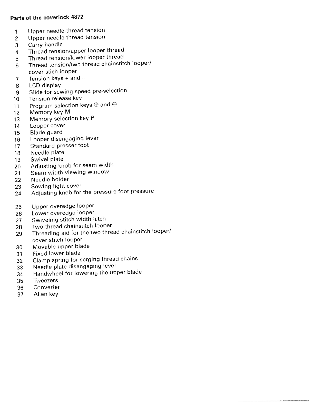
Pfaff coverlock 4872 User manual

PFAFF
coverlock
4872
‘F
U
U
I
PFAFF
coe10Ck
482
Instruction
Manual

N

Parts
of
the
coverlock
4872
1
Upper
needle-thread
tension
2
Upper
needle-thread
tension
3
Carry
handle
4
Thread
tension/upper
looper
thread
5
Thread
tension/lower
looper
thread
6
Thread
tension/two
thread
chainstitch
looper!
cover
stich
looper
7
Tension
keys
+
and
—
8
LCD
display
9
Slide for
sewing
speed
pre-selecfion
10
Tension
release
key
11
Program
selection
keys
EE
and
e
12
MemorykeyM
13
Memory
selection
key
P
14
Looper
cover
15
Blade
guard
16
Looper
disengaging
lever
17
Standard
presser
foot
18
Needle
plate
19
Swivel
plate
20
Adjusting
knob
for
seam
width
21
Seam
width
viewing
window
22
Needle
holder
23
Sewing
light
cover
24
Adjusting
knob
for
the
pressure
foot
pressure
25
Upper
overedge
looper
26
Lower
overedge
looper
27
Swiveling stitch
width
latch
28
Two-thread
chainstitch looper
29
Threading
aid
for
the
two
thread
chainstitch
looper!
cover
stitch
looper
30
Movable
upper
blade
31
Fixed
lower
blade
32
Clamp
spring
for
serging
thread
chains
33
Needle
plate
disengaging
lever
34
Handwheel
for
lowering
the
upper
blade
35
Tweezers
36
Converter
37
Allen
key

For
easier
understanding
of
this
instruction
book
pease
f&d
out this
and
the
bst
page when
reading.
Safety
ru’es
For
the
United
Kingdom only
The
eads
must
definitely
not
be
connected to
the
safety
lead
terminal
nor
to
a
plug
with
three
pins.
The
wires
in
the
mains
lead
are
colored
according
to
the
following
code:
Blue:
Neutral
Brown:
Live
As
the
colors
of
the
wires
in
the mains
lead
of
this
appliance
may
not
correspond
with
the
color
coding
of
the terminals
in
your
plug,
proceed
as
follows:
The
wire
which
is
colored
blue
must
be
connected
to
the
terminal
which
is
marked
with
the
letter
N
or
colored
black.
The
wire which
is
colored
brown
must
be
connected
to
the
terminal
which
is
marked
with
the letter
L
or
colored
red.
Cut-off
mains
plugs are
definitely
not to
be
used,
but
disposed
of
immediately.
Defective
mains leads
must
be
replaced
com
pletely.
Only
3A
spare
fuses
must
be
used
as
approved
by
ASTA
according
to
BS
1362
and the
fuse
cover
must
be
marked
3
A
or
with
the
corresponding
color
code.
The
plug
must
never
be
used
without
fuse
cover.
Spare
fuse
covers
are available
from
electrical
suppliers
or
the
PFAFF
agencies.
Please also
observe
the
general
safety
notes
on
page
2.
Important
safety instructions
For
Australia
only
•
If
the
supply
cord
is
damaged,
it
must
be
replaced
by
the
manufacturer
or
its
service
agent
or
a
similarly qualified
person
in
order
to
avoid
a
hazard.
•
The
appliance
is
not
intended
for
use
by
young children
or
infirm
persons
without supervision.
•
Young
children
should
be
supervised
to
ensure that
they
do
not play
with
the
appliance.
•
Switch
off
or
unplug the
machine when
leaving
it
unattended.
•
Before
servicing
the appliance
or
replacing
lamps,
unplug the
machine.
You
wiN
find
the
contents
on
page
4
and
5.

mportant
safety instructions
For
the
United
States
only
This
sewing machine
is
designed
and
manufactured
for
HOUSE
HOLD
use
only.
When
you
use
an
electric appliance,
the
follo
wing
basic
safety precautions
should always
be
adhered
to:
Read
all
instructions
before
using
this
sewing
machine.
DANGER
To
reduce
the
risk
of
electric
shock:
1.
The
sewing machine
should
never
be
left
unattended
when plugged
in.
Always
unplug
this appliance
from
the
electric
outlet
immediately
after
using
and before cleaning.
2.
Always
unplug
before
relamping.
Replace
bulb
with
same
type
rated
5
Watts.
3.
Do
not
reach
for
a
sewing machine
that
has
fallen
into
water. Unplug
immediately.
4.
Do
not
place or
store
a
sewing machine
where
it
can
tall
or be
pulled
into
a
tub
or
sink.
Do
not
place
in
or
drop
into
water
or
other
liquid.
V!ARNNG
To
reduce
the
risk
of
burns,
fire,
electric
shock,
or
injury
to
persons:
1.
Do
not
allow
to
be
used
as
a
toy.
Great
care
is
necessary
when this sewing
machine
is
used
by
or
near
children.
2.
only
use
this
sewing
machine
for
its
intended
purpose
as
described
in
this
manual.
Only
use
attachments
recommended
by
the
manufacturer
as
contained
in
this manual.
3.
Never
operate
this sewing machine
if
it
has
a
damaged
cord
or
plug,
if
it
is
not
working
properly,
if
it
has
been
dropped
or
damaged,
or
dropped
into
water.
Return
the
applian
ce
to
the
nearest
authorized
dealer
or
service
center
for
examination,
repair,
electrical
or
mechanical
adjustment.
4.
Never
operate
the sewing machine
with
any
air
openings
blocked.
Keep
ventilation
openings
of
the
sewing machine
and
foot
control
free
from
the
accumulation
of
lint,
dust
and loose
cloth.
5.
Never
drop
or
insert
anything
into
any
opening.
6. Do
not use
out
of
doors.
7. Do
not
operate
where aerosol
(spray)
products
are
being
used
or
where
oxygen
is
being
administered.
8.
To
disconnect,
turn
all
controls
to
off
(“0”)
position,
then remove
plug
from
socket.
9.
Never
operate
on
a
soft
surface
such
as
a
bed
or
couch
where
the
air
openings
may
be
blocked.
10.
Do
not
unplug
by
pulling
on
cord.
To
unplug,
hold
the
plug,
not
the
cord.
11.
Keep
fingers
away
from
all
moving
parts.
Special
care
is
required
around
the sewing
machine
needle.
12.
Always
use
the proper
needle
plate.
The
wrong
plate
can
cause
the needle
to
break.
13.
Do
not use
bent
or
blunt
needles.
Only
use
needles
recommended
by
the
manufacturer.
14.
Do
not
pull
or
push
fabric
while
stitching.
It
may
deflect
the needle,
causing
it
to
break.
15.
Switch
the sewing machine
off
(“0”)
when
making
any
adjustments
in
the needle
area,
such as
threading
needle,
changing
needle,
threading
bobbin,
oi
changing
presser
foot,
etc.
16.
Always
unplug
sewing
machine
from
the
electric
outlet
when
removing
covers,
lubrica
ting,
or
when
making
any
other
user
servicing
adjustments
mentioned
in
the instruction
manual.
17.
Hold
plug
when
rewinding
into
cord
reel.
Do
not
allow
plug
to
whip
when
rewinding.
Please also
observe
the
general
safety
notes
on
Page
2.
KEEP
THESE
1NSTRUC11ONS
N
A
SAFE
PLACE

Notes
on
safety
Notes
on
safety
for
domestic
sewing
machines
according
to
EN
60335-2-28 or
IEC
335-2-28.
1.
The
user
must
exercise
adequate
cau
tion
with
regard
to the
up
and-down
movement
of
the needle
and
constantly
observe
the
sewing
area
during
work.
2.
When
leaving
the
machine,
during
main
tenance
work
or
when
changing
mechan
ical
parts
or
accessories,
always
discon
nect
the
machine
from
the
main
power
by
unplugging
the
lead
cord
from
the
wall
outlet.
3.
The
maximum
permissible
wattage
for
the
sewing
lamp
is
5
watts.
4.
The
tension
of
the
belt
drive
must
only be
adjusted
by
a
PFAFF
mechanic.
5.
The
machine
must
be
put
into
operation
according
to the
indications
on
the
speci
fication
plate.
6.
Do
not place
any
objects
in
openings
on
the
machine.
7.
Do
not
use the sewing machine
if:
—
there
is
visible
damage,
—
its
function
is
defective,
—
it
is
wet,
e.g.
with
condensation
which
can
occur
when
a
cold
machine
is
brought
into
a
warm
room.
8.
Do
not
pull
the
mains
plug
out
of
the
socket
by its
cord.
9.
If
this appliance
is
used
for
another
pur
pose
than that intended
or
if
it
is
wrongly
operated,
we
cannot
accept
any
liability
for
any
damage
caused.
10.To
avoid
the
risk
of
electric
shock,
do
not
open
the
machine.
There
are
no
parts
inside the
machine
which
the
user
can
repair. This
is
the
exclusive
responsibility
of
our
qualified
service
staff.
11.Be
sure
to
use
only
original
PFAFF
parts.
supply
with
a
nominal
voltage
of
+1—
10
%
and
a
rated
frequency
of
+1—
4%.
13.
When
used
properly,
the
temperature
of
the
outer
components
of
a
non-electro
nically
controlled
foot
control
can
reach
up
to
85°
C.
Constant
use
at
a
low
speed
is
therefore
not
permitted
in
order
to
avoid
damage,
Environment
The
recommended
environment
is:
Ambient
temperature
50°
F
(10°
C)
to
104
°F
(40°
C)
Humidity
20
%
to
80
%.
Storage
temperature
-
13°
F
1-
25°
C)
to
+
140°
F
)60°
C).
The
machine
is
insensitive
to
interference,
but
it
should
not
be
used
in
the
direct
vicinity of
electronic
appliances
such
as
radios,
televisions,
PCs,
radio
transmitters,
etc.
This
machine
is
a
high
quality
electro
nic-mechanical appliance,
it
is
a
machine
for
supervised
use
in
the
home.lt
should
be
operated
in
such
a
way
that
t
is
not
subjec
ted
to:
dust,
severe
dampness,
direct
sunlight,
static
electricity,
heat-producing
objects,
corrosive chemicals
or
liquids.
To
permit
adequate
ventilation
the machine
must
be
kept
unblocked and
used
on
a
firm
and even
surface.
Treatment
Always
make
sure
not
to
damage
your
machine
by
knocking
or
dropping
st.
Cleaning
Housing
and
display:
To
clean
the housing,
use
a
dry,
clean
ml
soft
cloth
which
is
free
of
lint.
To
remuv”
any
stubborn
dirt,
use
a
soft
cloth with
.1
hol
or
paraffin.
Please Notel
Never
use
insecticides
or
chemical
products
such
as
petrol
(gas)
or
thin
chemic,tls
to
cle
an
the
housing.
12.
The
machine
is
designated
for
a
mains

Simpe,
up4odate
sewing
Congratulations!
You
have
bought
a
highquality
product
that
provides unique
advantages.
Your
new
coverlock
4872
can
take any
material
in
its
stride
and
will
sew
through
thick
and
thin for
you.
Your
PFAFF
coverlock
features
the
very
latest
in
design and
technology,
and
it
is
just as
easy
to
use
as this
instruction manual
is
to
follow.
If
you
now
take
a
bit of
time
to
study the
instruction manual
nothing
can
go
wrong.
It
is
certainly
time
well
spent,
since
it
is
the
only
way
to
find
out just
what
your
machine
can
do
and
make
full
use
of
all
its
features.
If
you
have
any
further
questions,
just
ask
your
PFAFF
dealer.
He
is
happy
to
be of
service
with
any
help
or
advice.
So
now
let’s
get
started
I
We
wish you
many
enjoyable
hours
creating your
very
own
fashion
ideas!
3

Contents
Page
Accessories
.
6
Accessories,
special
68,
69
Accessory
box
6
Adjusting
the
machine
to Prog.
1,
2, 3,
4
36,
37
Changing
a
spool
on
a
threaded
machine
24
Clamp
spring
30
Cleaning
the machine
65
Cone
thread
adapter
10
Converter,
attaching
33
Cover
stitch,
important
notes
on
sewing
51,
52
Differential
feed
38,
39
Differential
feed
setting,
changing
and
storing
42
Electrical
connection
7
Electrical
power
master
switch
7
Error
44
Foot
control,
connecting
7
Key
functions
40
Language,
choice
41
LCD
Display
40
Light
bulb
(sewing
lamp),
changing
67
Loopercover
8
Lubricating
the
machine
65
Machine
cover
6
Maintenance
65-
67
Needle
holder
13
Needle
inserting
tool
13
Needle plate
disengaging
lever
64
Needle plate,
removing
64
Needle
position
12
Needle
threader
25
Needle,
changing
13
Power
table
37
Presser
foot
11
Presser
foot
lifter
10
Presser
foot
pressure
29
Presser
foot,
changing
29
Program overview
46
-
48
Programmable
memories,
deleting
all
44
Programmable
memories, notes
on
storing
44
4

Contents
Page
Rubber
feet,
cleaning
...,.,....,...,...,......................
65
Safety
instructions
1,
2
Seam
width
adjusting
knob
34
Seam
width
viewing
window
34
Seam
width,
setting
34
Sewing
light
cover
67
Sewing
probiems
and
their
solutions
70,
71
Sewing
speed
pre-se(ection
29
Specifications
72
5
pooi
disc
10
Spool
holder
7
Stitch
formation
correction
measures
49
62
Stitch
length
adjustment
knob
35
Stitch
length
setting,
changing
and
storing
42
Stitch
length,
adjusting
35
Stitch
programs
programmable
memories,
activating
41
Stitch
width
latch,
swiveling
32
Telescoping
thread
guide
9
Tension
settings,
changing
and
storing
43
Thread chain
cutter
30
Thread
chart
63
Thread guide,
Clip-on
10
Thread
net
9
Thread
tension,
setting
45
Thread
unreeling
disc
9
Threading
aid
for
the
two
thread
chainstitch looper/cover
stitch
looper.
.
.
.
19,
21
Threading paths/overview
26
-
28
Threading the
lower
overedge
looper
(yellow>
16,
17
Threading the
needle(s)
22,
23
Threading the
two
thread
chainstitch looper cover
stitch
looper
(violet)
. . .
18
-
21
Threading
the
upper
overedge
looper
(pink)
15
Threading,
important
note
24
Threading/Thread guides
14
Upper
blade,
changing
66
Upper
blade,
disengaging
31
Upper
blade,
securing
35
Waste
container
8
5

Accessory
box
Open
the
accessory
box
56
by
gently
pres
sing
the
bottom
of
the
box
inwards.
The
fol
lowing
accessories
can
be
found
in
the
box:
1
Overlock
needle
system
EL
X
705,
cat.
no.
2002
2
Thread
nets
(5>
3
Thread unreeling
discs
(5>
4
Screw
driver
5
Needle
threader
6
Wrench
7
Needle
inserting
tool
8
Replacement
upper
blade
9
Clip-on
thread
guide
10
Transparent
presser
foot
(F>
for
cover
stitch
and
two-thread chainstitch
11
Machine
oil
12
Cleaning
brush
13
Edge
guide
Further
accessories
The
following
accessories
can
be
found
be
hind
the
swivel
plate
19:
1
Converter
2
Tweezers
3
Allen
key
Machine
cover
The
machine
cover
protects
the
machine
from
dust
and
dirt.
When
the
sewing
process
is
finished, push the
telescoping
thread
guide
39
together.
The
spool
stand
41
must
be
pushed
to
its
full
extent
into
the
machine,
regardless
of
whether
a
spool
is
lock
attached.
Place
the
cover over
the
machine.
The
accessories
should
be
stored
in
the
accessory
box
or
compartments
behind
the
swivel
plate.
6

I
/
III11I1
Operating
instructions
Electrical
connection
Connect the
lead
cord
between
the
socket
45
of
the
machine
and
the
wall
outlet.
Master switch
When you
turn
on
the
master
switch
46
the
sewing
lamp
is
illuminated.
The
machine
is
now
operational.
(/____•S\
1I1!II!!IIII
Connecting
the
foot
control
Connect the
plug
of
the
foot
control
to
the
connection
socket
47
of
the
machine.
The
pre-selected
sewing
speed
range
(see
page
29) is
regulated
by
pressing the
foot
control.
I
Notes
on
safety
This
appliance
has
a
polarized
plug
(one
blade wider than the
other).
To
reduce the
risk
of
electric
shock,
this
plug
is
intended
to
fit
in
a
polarized
out
let
only
one
way.
If
the
plug
does
not
fit
fully
in
the
outlet,
reverse the
plug.
If
it
still
does
not
fit,
contact
a
qualified
elec
trician
to
install
the
proper
outlet.
Do
not
modify
the
plug
in
any
way.
For
control
sewing machine,
foot
con
troller
type
F
8
VC-485
has
to
be
used.
Ii
7

Looper
cover
Push
the looper cover
14
fully
to
the
right
and
then
swivel
it
down.
Five
types
of
stit
ches
and
their
threading
paths
are
portray
ed
in
color
on
the
inside
of
the
looper
cover.
Note: The
electricity
supply
of
the machine
is
cut
off
as
soon
as
the
looper
cover
or
swi
vel
plate
19 is
opened,
for
safety reasons,
i.e.
sewing
with
the machine
is
no
longer
possible.
-‘
!
PFAFF
Waste
container
Insert
the
upper
latch
of
the
waste
container
53
into
the
upper
slot
of
the
looper
cover
14.
Apply
pressure
to
the
lower
part
of
the
con
tainer
until
the
lower
latches
click
into
place
in
the
lower
slots
of
the
looper
cover.
To
remove the
waste
container,
repeat
this
procedure
in
the
reverse
order.
cjr
8

—
—
Spool
holder
Before
placing
thread cones/spools
on
machine
you
must
pull
the
spool holder
41
fully
away
from
the
back
of
machine.
Thread
net
&
Synthetic
threads
generally
unwind too
quickly
from
the
thread
spool.
Thread
nets
have been
included
to
allow
easy
use
of
the
se
threads.
Pull
the
thread
net (located
in
the
accessory
box)
over
the
spool
from
be
low.
Place
the
spool
on
the
spool
holder
cat
ching
the bottom
of
the
thread
net
with
the
spool
pin.
_1
Pcnrc
Telescoping
thread
guide
Pull
the
telescoping
thread
guide
39
upwards
to
its
highest
position.
To
ensure
optimum
thread
feed,
turn
the
telescoping
parts
slowly
until
you
hear the
locking
balls
click
into
place.
The
thread
unreeling
disc
(in
the
accessory
box)
is
used
for small
spools/spools
with
notched
or
rough
ends.
Place
the
spool
on
the
spool
pin
42.
Place
the
thread
unreeling
disc
on
top
of
the
spool.
Make
sure the
spool
disc
44
is
used
under
the
spool.
Thread
unre&ing
disc
9

It
is
advantageous
to
use the
thread
unree
ling
disc
44 when
sewing
with
large
spools
(5,000
—
10,000
m).
To
do this, place
the
cone
thread
adapter
43
onto
the
spool
pin
42.
With
synthetic
threads,
the
spool discs
take
up
any
play
or
surplus
in
the
thread
and
guarantee
excellent
thread
feed.
Presser
foot
lifter
The
presser
foot can
be
raised
and
lowered
using
the
presser
foot
lifter
51.
The
maxi
mum
vertical
lift
of
6.5
mm
for
the
presser
foot
for
particularly
thick
fabrics
can be
achieved
by
pressing
the
presser
foot
lifter
towards
the
rear.
Clip-on
thread
guide
Use
the
clip-on
thread
guide
accessory
when
sewing
with
decorative
thread.
Clip
this onto the
telescoping
thread
guide
39
and
thread
the
machine
as
shown
in
the
il
lustration.
Use
the
thread
net
and
the
thread
unreeling
disc.
Once
an
initial
thread
chain
has
been
crea
ted,
the
presser
foot
lifter
no
longer
needs
to
be
raised
if
you
continue
working
with
the
same thread
and
presser
foot,
It
is
suffi
cient
to
gently
lift
the
front part
of
the
pres
ser
foot using
your
thumb.
Slide
the
fabric
under
the raised
part
of
the
presser
foot.
The
fabric
is
automatically
taken
up
and
fed
into
the machine
when
you
activate the
foot
control.
ill!
Spool
disc/cone
thread
adapter
\
/
10

Presser
foot
•\
‘4
\
‘
With
the
standard
presser
foot
10
use
the
setting
“A”
of
the
spring-loaded
presser
foot
latch
for
the
cover
stitch
programs
(Progs.
1,
2,
3),
the
two-thread
chainstitch
(Prog.
4),
the
4-thread
safety-stitch
seam
(Prog.
191
and the
5-thread safety-stitch
seam
(Prog.
20)-
The
transparent
presser
foot
F
from
the
accessories
can
also
be
used
for
the cover
stitch
(Prog.
1,
2,
3)
and the
two-thread
chainstitch
(Prog.
4).
For
all
other
programs
use the
standard
presser
foot
10
and
the
setting
“B”
for
the
spring-loaded
presser
foot
latch.
Changing
the
presser
foot
Switch
off
the
eectricaI
power
To
remove:
Raise
the
needle(s)
to
the
highest
position
by
turning
the handwheel
towards
you.
Raise
the
presser
foot and
press
the
lever
A
at
the
rear
of
the
presser
foot
holder.
Pivot
the
presser
foot
clockwise
until
the
front
half
of
presser
foot
clears
holder
and
remove
by
sliding
foot
away
from
you
towards
back
of
machine.
To
attach:
Place
the
presser
foot
behind and
perpendicular
to
the
sewing
foot
holder.
Pivot
the
presser
foot
counterclockwise
until
the
pin
of
the
foot
is
directly
under
the
presser
foot
holder
clamp.
Lower
the
presser
foot
lever and
press
lever
A,
if
necessary,
until
the
foot
then
clicks into
place.
Check:
Please
lift
the
presser
foot
lever
to
ensure
that
the
presser
foot
is
properly
locked
into
place.
I
11

Need’e
position
This
machine
has
5
needle
positions
and
can
sew
with
a
maximum
of
three
needles
at
any
one
time.
The
needle
positions
concerned
are
LO,
Li,
L2,
Ri
and
R2.
The
tightening/fastening
screw
is
located
directly
above
the
corresponding
needle.
Note:
If
the
needles
LO,
Li
and
L2
have
been
inserted,
the
left
needle
will
be
the lowest
of
the
three.
The
different
needle
positions
are
depicted
in
a
schematic
drawing
in
the
instruction
manual.
Also
refer
to
the
examples
above
and
below.
Insert
the
needle(s)
as
shown
on
the
LCD
display.
Note:
If
both
the
needles
R2
and
Ri
have
been
inserted,
the
left
needle
will
be
so
mewhat
higher
than
the
right
needle.
If
the
needles
L1
and
L2
have
been inserted,
the
left
needle
will
be
somewhat
lower
than
the
right
needle.
If
the needle
LO
and
L2
have
been
inserted,
the
left
needle
will
also
be
lower
than
the
right
needle.
o
1L2R2
0
12
1R2
EU
0
1L21R2
EILU
0
1L21fl2
0
1L2
1R2
o
1L2
1R2
UJ’EJ
1L21R2
V
12

Changing
the
needle
Switch
off
the
eectrica
power
To
remove:
Lower
the
presser
foot
and
move
the
needle(s)
to
the
highest
position
by
turning
the
handwheel.
Push
the needle
inserting
tool
(from
the
accessory
box
56)
from
below
upward
fully
over
the needle.
Loosen
the
fastening screw
of
the
needle
(without
removing
it)
with
the
Allen
key
and
pull
the needle
down
to
remove.
To
insert:
Insert
the
needle
into
the
hole
E
of
the
needle
inserting
tool, so
that
the
flat
needle shank
K
laces
the
flat
side
L
of
the
in
serting
tool.
Now
insert
the needle
fully
into
the holder
and
tighten
the
fastening
screws.
Remove
the
needle
inserting
tool.
Overlock
needle types
EL
X
705,
cat.
no.
2002
are
required
for
this
machine.
I
I
I
13

Threading
the
thread
guides
Place
the
spools
on
the
spool
pins
42.
You
will
find
information
on
the
thread
net,
thre
ad
unreeling
disc,
reel
disc
and
cone
thread
adapter
on
pages
9
and
10.
Thread
through
the
thread guides
38
from
the
back
to
the
front
following
the
colored
threading
paths.
Pull
the carry
handle
3
upwards.
Thread
through
the
underside
of
the
carry
handle
and
through
the
rear
thread guides
52
using
both
hands
to
pull
the
thread
down
until
it
slips
under
the
thread
guide.
Guide
the
thread through
the
tension
discs and
pull
it
down
until
it
is
positioned
firmly
between
the
tension
discs.
Return
the
carry
handle
to
its
original
position.
‘tj
I
11
r
I
\\
ria-
Note:
Thread
in
a
sequence
of
1
to
5.
14

Threading
the
upper
overedge
‘ooper
(pink)
i
—
If
11
L
I
3I
I
—
I
Thread
through
the
thread
guides
1
to
8,
which are
marked
with
a
pink
dot.
Turn
the
handwhe&
towards
you
until
the
upper
overedge
looper
25
is
in
its
highest
position.
Thread
in
a
sequence
of
1
to
9.
Note:
To
make
this
task
easier,
use the
tweezers
which
can
be
found
behind
the
swivel
plate.
Thread
from
the front
through
the
eye
of
the
upper overedge
looper
9.
Pull
approximate
ly
4”
(10
cml
of
thread through
the
looper
and
place
it
to
the
left
under
the
presser
foot.
5-.
;___
4
1.
4
65
.1
15

Threading
the
‘ower
overedge
‘ooper
(yeflow)
Turn
the
handwheel
towards
you
until
the
lower
overedge
looper 26
is
on
the
extreme
right.
To
make
this
task
easier,
use
the
tweezers
which can
be
found behind
the
swivel
plate.
7
1
Threadinasequenceofi
to
10.
,-
Note:
2
in
JJL
5
—
16
Other manuals for coverlock 4872
1
Table of contents
Other Pfaff Sewing Machine manuals

Pfaff
Pfaff tiptronic 2040 User manual

Pfaff
Pfaff hobbylock 4762 User manual

Pfaff
Pfaff fashion User manual

Pfaff
Pfaff hobby 1122 Guide

Pfaff
Pfaff expression 2.0 User manual

Pfaff
Pfaff 1051 User manual

Pfaff
Pfaff 1445 User manual

Pfaff
Pfaff Creative Vision User manual

Pfaff
Pfaff 1213 User manual

Pfaff
Pfaff 487 User manual

Pfaff
Pfaff 1243-712/02 Guide

Pfaff
Pfaff coverlock 4862 User manual

Pfaff
Pfaff 93 User manual

Pfaff
Pfaff Creative Vision User manual

Pfaff
Pfaff hobbylock 795 User manual

Pfaff
Pfaff Ccreative 2.0 User manual

Pfaff
Pfaff 339 User manual

Pfaff
Pfaff POWERLINE 3741 User manual

Pfaff
Pfaff POWERline 2591 ME User manual

Pfaff
Pfaff performance 5.0 User manual