Pfaff 8304-020 User manual

INSTRUCTION MANUAL
296-12-18 418/002
Betriebsanleitung engl. 06.09
This instruction manual applies to machines from the
following serial numbers onwards:
# 11 031
8304 -020
Industrial
®

The reprinting, copying or translation of PFAFF Instruction Manuals, whether in whole or
in part, is only permitted with our previous authorization and with written reference to the
source.
PFAFF Industriesysteme
und Maschinen AG
Hans-Geiger-Str. 12 - IG Nord
D-67661 Kaiserslautern

Contents
Contents ................................................................................. Chapter - Page
1Safety ............................................................................................................................ 1 - 1
1.01 Regulations ................................................................................................................... 1 - 1
1.02 General notes on safety ................................................................................................. 1 - 1
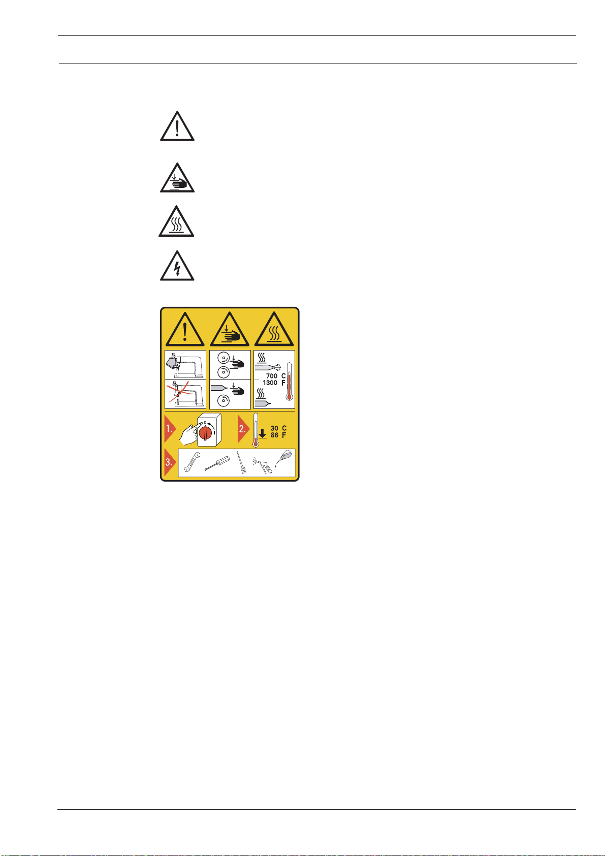
1.03 Safety symbols ............................................................................................................. 1 -2
1.04 Important points for the user.......................................................................................... 1 - 2
1.05 Operating and technical personnel ................................................................................. 1 - 3
1.05.01 Operatingpersonnel ....................................................................................................... 1 - 3
1.05.02 Technicalpersonnel ....................................................................................................... 1 - 3
1.06 Dangerwarning ............................................................................................................. 1 -4
2Proper use .................................................................................................................... 2 -1
3Specifications .............................................................................................................. 3 - 1
4Disposal of the machine .............................................................................................. 4 - 1
5Transport, packing and storage .................................................................................. 5 - 1
5.01 Transport to the customer’s premises ........................................................................... 5 - 1
5.02 Transport within the customer’s premises ..................................................................... 5 - 1
5.03 Disposal of packing ....................................................................................................... 5 - 1
5.04 Storage .......................................................................................................................... 5 - 1
6Explanation of the symbols ........................................................................................ 6 - 1
7Controls........................................................................................................................7- 1
7.01 Main switch ..................................................................................................................7- 1
7.02 Foot switch ................................................................................................................... 7 - 1
7.03 Locking foot switch (optional) ........................................................................................ 7 - 2
7.04 Temperatureregulator/faultindicator............................................................................ 7 - 2
7.05 Status display of temperature control ............................................................................ 7 - 3
7.06 Regulator for drive roller start delay ............................................................................... 7 - 3
7.07 Regulator for heat-sealing speed.................................................................................... 7 - 4
7.08 Selection switch for operational modes ......................................................................... 7 - 4
7.09 Regulator for hot-air pressure (only on machines with hot-air) ....................................... 7 - 5
7.10 Regulatorfor feed rollerpressure ................................................................................... 7 - 5

Contents
Contents ................................................................................. Chapter - Page
8Installation and commissioning ................................................................................. 8 - 1
8.01 Installation ..................................................................................................................... 8 - 1
8.01.01 Adjusting the table height .............................................................................................. 8 - 1
8.01.02 Connecting the compressed air ..................................................................................... 8 - 2
8.02 Commissioning ............................................................................................................. 8 - 2
8.03 Switching the machine on/off ........................................................................................ 8 - 3
9Setting up ..................................................................................................................... 9- 1
9.01 Inserting the sealing tape............................................................................................... 9 - 1
9.01.01 Adjusting the tape reel bracket to the size of the tape reel ............................................. 9 - 1
9.01.02 Adjusting the tape width and the tape brake .................................................................. 9 - 2
9.02 Adjustingthepenetrationdepth ..................................................................................... 9 - 3
9.03 Feed rollers and hot-air pressure, heat-sealing temperature and speed .......................... 9 - 3
10 Heat sealing ................................................................................................................10 - 1
10.01 Heat-sealingprinciple ...................................................................................................10 - 1
10.02 Heat-sealing process ....................................................................................................10 - 1
11 Care and maintenance ................................................................................................11 - 1
11.01 Cleaning .......................................................................................................................11 - 1
11.01.01 Machines with hot wedge ............................................................................................11 - 1
11.01.02 Machines with hot-air nozzle ........................................................................................11 - 1
11.02 Check the air pressure..................................................................................................11 - 2
11.03 Draining the water bowl of the air filter/regulator/cleaning the filter ...............................11 - 2
11.04 Draining the water bowl of the fine filter/changing the fine filter ....................................11 - 3
11.05 Lubricating the drive chains ..........................................................................................11 - 4

Contents
Contents ................................................................................. Chapter - Page
12 Adjustment ..................................................................................................................12 - 1
12.01 Notesonadjustment ....................................................................................................12 - 1
12.02 Tools, gauges and other equipment ..............................................................................12 - 1
12.03 Hot-airnozzle ................................................................................................................12 - 2
12.03.01 Side and angle alignment of the hot-airnozzle ...............................................................12 - 2
12.03.02 Height adjustment and distance of the hot-air nozzle from the feed rollers ....................12 - 3
12.04 Adjusting the hot wedge ...............................................................................................12 - 4
12.04.01 Hot wedge crosswise to feed direction .........................................................................12 - 4
12.04.02 Height adjustment of the hot wedge .............................................................................12 - 5
12.04.03 Distance of the hot wedge to and its contact pressure on the feed rollers ....................12 - 6
12.04.04 Grindingthe hotwedge .................................................................................................12 - 7
12.05 Changingtheheating cartridge......................................................................................12 - 8
12.06 Changingthetemperatureprobe ...................................................................................12 - 9
12.07 Drive chains .................................................................................................................12 - 6
12.07.01 Tensioning the main drive chains..................................................................................12 - 10
12.07.02 Tensioning drive chain in bottom post and to top feed roller..........................................12 - 11
12.08 Fuses ...........................................................................................................................12 - 12
13 Circuit diagrams .........................................................................................................13 - 1

Safety
1 - 1
1 Safety
1.01 Regulations
This machine was built in accordance with the European regulations listed in the conformity
and manufacturer’s declarations.
In addition to this instruction manual, also observe all generally accepted statutory and other
regulations and legal requirements - including those of the country in which the machine will
be operated and all valid environmental-protection regulations. Regionally applicable
regulations of the social insurance society for occupational accidents or other supervisory
organisations are to be strictly adhered to!
1.02 General notes on safety
●This machine may only be operated by adequately trained operators and only after the
instruction manual has been completely read and understood !
●The danger and safety instructions on the machine itself are to be followed!
●The machine may only be used for the purpose for which it was intended and must not
be operated without its safety devices. Observe all relevant safety regulations!
●When replacing the feed rollers or the hot wedge, when leaving the workplace
unattended and during servicing or repairs, the machine must be switched off at the
mains switch and the plug pulled!
●Daily servicing work may be carried out only by appropriately trained personnel!
●Repairs and special maintenance work may be carried out only by technicians or persons
with appropriate training!
●Work on the electrical equipment may be carried out only by qualified electricians!
●Work is not permitted on live parts and equipment! Exceptions to this are contained in
the regulations EN 50110.
●Modifications and alterations to the machine may only be carried out under observance of
all the relevant safety regulations!
●Only spare parts which have been approved by us are to be used for repairs! We
expressly point out that any replacement parts or accessories not supplied by us have not
been tested and approved by us. The installation and/or use of any such products can
lead to negative changes in the structural characteristics of the machine. We shall not be
liable for any damage which may be caused by non-original parts.

Safety
1 - 2
1.04 Important points for the user
●This instruction manual is a component part of the machine and must be available to
operating personnel at all times.
The instruction manual must be read before commissioning the machine.
●The operating and technical personnel are to be instructed as to the machine’s safety
mechanisms and with regard to safe working methods.
●It is the duty of the owner to operate the machine only when it is in perfect running order.
●The owner is obliged to ensure that none of the safety mechanisms are removed from
the machine or deactivated.
●When processing PVC, PTFE and similar materials, the user must ensure that the
maximum permissible level of toxic fumes is not exceeded.
●The user must make sure there is no high-frequency welding equipment being operated
in direct proximity to the machine that exceeds the EMC limit values according to
EN 60204-31 for the machine.
For further information please refer to the sales agency responsible.
1.03 Safety symbols
Danger!
Special points to observe.
Danger of hands being crushed!
Danger of burns from hot surface!
Danger from electric voltage!
o
o
o
o
Caution
Do not operate without finger guard and safety devices.
Turn off the main switch and let the machine cool
down before any setting up, maintenance or cleaning
work!

Safety
1 - 3
1.05 Operating and technical personnel
1.05.01 Operating personnel
Operating personnel are persons responsible for setting up, operating and cleaning the
machine as well as for eliminating any faults which may occur.
Operating personnel must observe the following:
●Always comply with the notes on safety in the instruction manual!
●Never adopt a working method which could have an adverse effect on the level of safety
in using the machine!
●Never wear loose-fitting clothing or jewelry such as chains or rings!
●Ensure that only authorized persons have access to the danger zone around the machine.
●Always report any changes in the machine, which may limit its safety, to the
immediately!
1.05.02 Technical personnel
Technical personnel are persons with special training in the fields of electrical/electronics
engineering and mechanics. They are responsible for the lubrication, maintenance and
repair of the machine.
Technical personnel must observe the following:
●always comply with the notes on safety in the instruction manual!
●switch the machine off at the main switch before carrying out servicing or repair work!
●never work on live parts and equipment! Exceptions are contained in the regulations EN
50110.
●replace the protective coverings after all repairs or maintenance work.

Safety
1 - 4
Do not operate the machine without the protective cover 1!
Danger of burns if the heating element 2is touched!
Do not put your fingers between protective cover 1and swivel unit 3!
Danger of crushing when swivel unit 3is swung in and out of place!
Fig. 1 - 01
12
3
1.06 Danger warning

Proper use
2 - 1
2 Proper use
The PFAFF 8304-020 is a heat-sealing machine with straight post, available both as the hot-
air or hot wedge model.
The purpose of the machines is to heat-seal flexible thermoplastic materials such as e.g.
protective covers, PVC-clothing, insulating and filter tubes, small tarpaulins and small tents,
motorbike seats etc.
Any and all uses of this machine which have not been approved of by the
manufacturer are considered to be inappropriate! The manufacturer cannot be
held liable for any damage caused by inappropriate use of the machine!
Appropriate use of the machine presupposes the observance of all operational,
adjustment, maintenance and repair measures required by the manufacturer!

Specifications
3 - 1
3 Specifications ▲
Dimensions and weight:
Length:.................................................................................................... approx. 1265 mm
Breadth: .................................................................................................... approx. 600 mm
Height: (without tape reel bracket) ......................................................... approx. 1450 mm
Weight: ........................................................................................................ approx. 110 kg
Mains voltage
set for: ...................................................................... 230 V± 10%, 50/60 Hz, single-phase
Power input (hot wedge model): ............................................................... approx. 1200 W
Power input (hot-air model):....................................................................... approx. 3500 W
Max. heating capacity (hot wedge model): ............................................................. 1000 W
Max. heating capacity (hot-air model): .................................................................... 3300 W
Mains fuse protection: .................................................................................................. 16A
Working air pressure ................................................................................................... 5 bar
Air consumption (hot wedge model): .....................................................................30 l/min.
Air consumption (hot-air model): ................................................................... 60 – 120l/min.
Hot air pressure (only for hot-air model):.......................................................... min. 0.3 bar
Max. heat-sealing speed: .................................................................................... 10 m/min.
Max. heat-sealing temperature(hot wedge model): .......................................... max. 450°C
Max. heat-sealing temperature(hot air model): ................................................. max. 650°C
Heat-sealing tape width: ................................................................................. up to 25 mm
▲ Subject to alteration

Disposal of the machine
4 - 1
4 Disposal of the machine
●The proper disposal of the machine is the responsibility of the customer.
●The materials used on the machine are steel, aluminium, brass and various plastics.
The electrical equipment consists of plastics and copper.
●The machine is to be disposed of in accordance with the locally valid environmental
protection regulations.
Special care is to be taken that parts soiled with lubricants are disposed of
separately in accordance with the locally valid environmental protection
regulations.

Transport, packing and storage
5 Transport, packing and storage
5.01 Transport to the customer’s premises
Within Germany the machine is delivered without packing. Machines for export are packed.
5.02 Transport within the customer’s premises
The manufacturer bears no liability for transport within the customer’s premises.
5.03 Disposal of packing
The packing of this machine consists of paper, cardboard, fusible fabric and wood. Proper
disposal of the packing is the responsibility of the customer.
5.04 Storage
If not in use, the machine can be stored for up to six months as it is. During this time it
should be protected against dust and dampness.
If the machine is stored for longer periods, its parts, especially moving parts, must be
protected against corrosion, e.g. by a film of oil.
5 - 1

Explanation of the symbols
6 - 1
6 Explanation of the symbols
In this Instruction Manual, tasks to be carried out and important information are drawn to
your attention by symbols. The symbols have the following meanings:
Note, information
Cleaning, care
Lubrication
Servicing, repairing, adjustment, maintenance
(only to be carried out by specialist personnel)

Controls
7 - 1
7 Controls
7.01 Main switch
●The machine is switched on or off by
turning main switch 1.
Position " 0 " : Machine is switched off
Position " I " : Machine is switched on
When switching off the
machine, please observe the
notes in Chapter 8.03
Switching the machine on
and off!
Fig. 7 - 01
1
7.02 Foot switch
●Following functions are triggered by foot
switch 1.
Position 1:Positioning the workpiece (top
feed roller is lowered)
Position 2:Starting the heat-sealing pro-
cess (the heating element is
swung into position/feed rollers
are started)
The functions triggered by
pedal 1differ according to the
operational mode of the machine
(see Chapter 7.08 Operational
modes-selection switch).
Fig. 7 - 02
1

Controls
7 - 2
7.04 Temperature regulator / fault indicator
●The temperature can be set with the
buttons 1.
●Display 2shows the required value and
display 3the actual value.
●When the following faults occur, fault
indicator 4lights up:
- Fault on temperature regulator or sensor.
- Overheating of the heating cartridge.
- hot-air pressure too low.
When a fault has occurred:
●Eliminate the fault.
●Acknowledge elimination of fault by
pressing fault indicator button (lamp off).
Fig. 7 - 04
1
3
2
4
7.03 Locking foot switch (optional)
●Following functions are triggered by foot
switch 1and 2.
Switch 1:Positioning the workpiece (top
feed roller is lowered)
Switch 2:Starting the heat-sealing pro-
cess (the heating element is
swung into position/feed rollers
are started)
The functions triggered by
pedal 1differ according to the
operational mode of the machine
(see Chapter 7.08 Operational
modes-selection switch).
Fig. 7 - 03
1
2

Controls
7 - 3
7.05 Status display of temperature control
●Depending on the status of the
temperature control, diodes 1 - 6 light up.
Diode 1lights up when the actual
temperature deviates from the
required temperature by +/-50°C.
Diode 2lights up, if the temperature
exceeds 650°C, or if the sensor
breaks.
Diode 3- no function
Diode 4- no function
Diode 5lights up as soon as the heating is
switched on.
Diode 6lights up when the machine is
heated.
Fig. 7 - 05
1
3
2
4
5
6
7.06 Regulator for drive roller start delay
●On regulator 1the time can be set, when
the drive roller is activated after the
heating element has been swung into
position.
Fig. 7 - 06
1

Controls
7 - 4
7.08 Selection switch for operational modes
●The operational modes of the machine
can be set with the selection switch 1by
means of four switch settings. The
functions are triggered by two switch
positions on the pedal, or, if there are
two pedals, by pedal 1and 2.
1 = heat-sealing
Position 1/pedal 1 - top feed roller is lowered
Position 2/pedal 2 - heating element swings
into position, feed rollers
run forwards
2 = Test run 1
Position 1/pedal 1 - top feed roller is lowered
Position 2/pedal 2 - heating element swings
into position
3 = Test run 2
Position 1/pedal 1 - top feed roller is lowered
Position 2/pedal 2 - feed rollers run forwards
4 = Reverse
Position 1/pedal 1 - top feed roller is lowered
Position 2/pedal 2 - heating element swings
into position, feed rollers
run backwards
Fig. 7 - 08
1
7.07 Regulator for heat-sealing speed
●The heat-sealing speed is set with
regulator 1.
●Regulator 2has no function.
Fig. 7 - 07
1
2

Controls
7 - 5
7.09 Regulator for hot-air pressure (only on machines with hot-air)
●The hot-air pressure is adjusted by
turning regulator 1.
●The hot-air pressure level can be read
from pressure gauge 2.
The hot-air pressure must not
drop below 0.2 bar!
If the hot-air pressure is too
low, there is a risk of the
heating element burning out.
The heating therefore switches
off automatically when the hot-
air pressure is too low.
Fig. 7 - 09
1
2
7.10 Regulator for feed roller pressure
●The feed roller pressure is adjusted by
pulling out and turning regulator 1.
●The pressure level can be read from
pressure gauge 2.
Fig. 7 - 10
1
2

Installation and commissioning
8 - 1
8 Installation and commissioning
The machine must only be installed and commissioned by qualified personnel!
All relevant safety regulations must be observed!.
8.01 Installation
Suitable connections for power and compressed air, an even and firm floor surface and
sufficient lighting must be provided for at the installation site.
8.01.01 Adjusting the table height
Fig. 8 - 01
11
lLoosen screws 1and set the table at the required height.
lTighten screws 1firmly again.
Table of contents
Other Pfaff Sewing Machine manuals

Pfaff
Pfaff 481 User manual

Pfaff
Pfaff 90 User manual

Pfaff
Pfaff 3538-30/02 User manual

Pfaff
Pfaff 114 User manual

Pfaff
Pfaff Creative 2134 User manual

Pfaff
Pfaff expression line User manual

Pfaff
Pfaff 1181 Guide

Pfaff
Pfaff 1196 User manual

Pfaff
Pfaff expression 2.0 User manual

Pfaff
Pfaff EXPRESSION 2038 - User manual

Pfaff
Pfaff 3114 User manual

Pfaff
Pfaff 5625-657/01 User manual

Pfaff
Pfaff 8304-040 User manual

Pfaff
Pfaff 300 e User manual

Pfaff
Pfaff tiptronic 6232 User manual

Pfaff
Pfaff PowerLine 2235 User manual

Pfaff
Pfaff 461 User manual

Pfaff
Pfaff 3734-2/01 User manual

Pfaff
Pfaff 3117 User manual

Pfaff
Pfaff 3371-10 series Guide