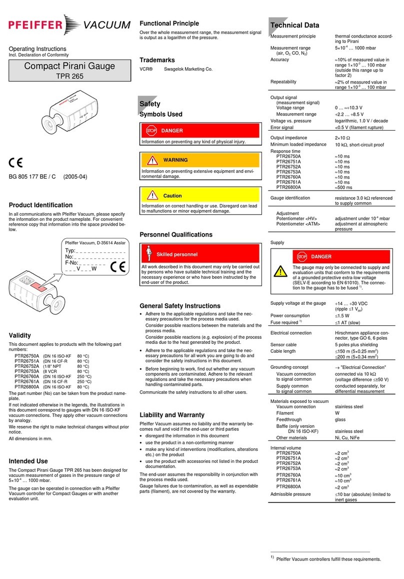
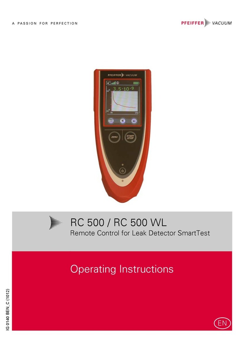
Pfeiffer TPR 280 User manual

Operating Instructions
Incl. Declaration of Conformity
Compact Pirani Gauge
TPR 280
TPR 281
BG 805 178 BE / D (2006-02)
Product Identification
In all communications with Pfeiffer Vacuum, please specify
the information on the product nameplate. For convenient
reference copy that information into the space provided
below.
Typ:
No:
F-No:
V W
Pfeiffer Vacuum, D-35614 Asslar
Validity
This document applies to products with the following part
numbers:
TPR 280
(W filament)
TPR 281
(Ni filament)
PTR26950
PTR26951
PTR21950 (DN 16 ISO-KF)
PTR21951 (DN 16 CF-R)
PTR26960
PTR26961
PTR21960 (DN 16 ISO-KF long tube)
PTR21961 (DN 16 CF-R long tube)
The part number (No) can be taken from the product name-
plate.
If not indicated otherwise in the legends, the illustrations in
this document correspond to gauges with DN 16 ISO-KF
vacuum connections. They apply other vacuum connections
by analogy.
We reserve the right to make technical changes without prior
notice.
All dimensions in mm.
Intended Use
The Compact Pirani Gauges TPR 280 and TPR 281 have
been designed for vacuum measurement of gases in the
pressure range of 5×10⁻⁴ … 1000 mbar.
The gauges must not be used for measuring flammable or
combustible gases which react in air.
They can be operated in connection with a Pfeiffer Vacuum
controller for Compact Gauges or with another evaluation
unit.
Safety
Symbols Used
DANGER
Information on preventing any kind of physical injury.
WARNING
Information on preventing extensive equipment and envi-
ronmental damage.
Caution
Information on correct handling or use. Disregard can lead
to malfunctions or minor equipment damage.
Personnel Qualifications
Skilled personnel
All work described in this document may only be carried
out by persons who have suitable technical training and
the necessary experience or who have been instructed by
the end-user of the product.
General Safety Instructions
•Adhere to the applicable regulations and take the nec-
essary precautions for the process media used.
Consider possible reactions between the materials and the
process media.
Consider possible reactions of the process media due to
the heat generated by the product (e.g. explosions).
•Adhere to the applicable regulationsand take the neces-
sary precautions for all work you are going to do and
consider the safety instructions in this document.
•Before beginning to work, find out whether any vacuum
components are contaminated. Adhere to the relevant
regulations and take the necessary precautions when
handling contaminated parts.
Communicate the safety instructions to all other users.
Liability and Warranty
Pfeiffer Vacuum assumes no liability and the warranty be-
comes null and void if the end-user or third parties
•disregard the information in this document
•use the product in a non-conforming manner
•make any kind of interventions (modifications, alterations
etc.) on the product
•use the product with accessories not listed in the product
documentation.
The end-user assumes the responsibility in conjunction with
the process media used.
Gauge failures due to contamination, as well as expendable
parts (filament), are not covered by the warranty.
Technical Data
Measurement principle thermal conductance according
to Pirani
Measurement range
(air, O2, CO, N2)
5×10⁻⁴ … 1000 mbar
Accuracy (N2)
1×10⁻³ … 100 mbar ±15% of reading
5×10⁻⁴ … 1×10⁻³ mbar ±50% of reading
100 … 1000 mbar ±50% of reading
Resolution 1% of reading
Repeatability with air
1×10⁻³ … 100 mbar 2% of reading
Output signal
(measurement signal)
Voltage range VDC 0 … +9.0
Measurement range VDC +2.2 … +8.5
Voltage vs. pressure logarithmic
1.0 V/decade
Error signal V 0 … +0.5
(filament rupture)
Output impedance Ω2×4.7
Minimum loaded
impedance
kΩ10, short-circuit proof
Response time ms 80
Gauge identification 3.0 kΩ, referenced to supply
common (voltage at pin 1 ≤5 V)
Adjustment one tactile switch for ATM and
HV adjustment
Supply
DANGER
The gauge may only be connected to power
supplies, instruments or control devices that
conform to the requirements of a grounded
extra-low voltage (SELV-E according to
EN 61010). The connection to the gauge has to
be fused 1).
Supply voltage
At gauge VDC +14 … +30
Ripple Vpp ≤1
Current consumption mA <500
(max. starting current)
Power consumption W ≤1
Fuse required 1) AT
(slow)
1
Electrical connection Hirschmann appliance
connector, male,
type GO 6, 6 poles
Sensor cable 5 poles plus shielding
Cable length ≤150 m (5×0.25 mm2)
≤200 m (5×0.34 mm2)
Grounding concept →"Electrical Connection"
Vacuum connection to
signal common
connected via 1 MΩ
(voltage difference <15 V)
Supply common to
signal common
conducted separately, for
differencial measurement
Materials exposed to
vacuum
DIN 1.4301, DIN 1.4305,
DIN 1.4435, glass, Ni,
NiFe
Filament
PTR26xxx
PTR21xxx
W
Ni
Internal volume
PTR26950, PTR21950
PTR26951, PTR21951
cm3
cm3
≈1.5
≈1.5
PTR26960, PTR21960
PTR26961, PTR21961
cm3
cm3
≈10
≈10
Admissible pressure bar
(abs.)
10, limited to inert gases
1) Pfeiffer Vacuum controllers fulfill these requirements.
(505)872-0037
idealvac.com
idealvac.com

Admissible temperatures
Operation °C
+5 … +60
Vacuum connection
DN 16 ISO-KF
DN 16 CF-R
°C
°C
80 2)
80 2)
in horizontal moun-
ting orientation
Filament °C 110
Storage °C –20 … +65
Relative humidity % ≤80 at temperatures up to
≤+31 °C, decreasing to 50
at +40 °C
Use indoors only, altitude up to
2000 m NN
Mounting orientation any
Degree of protection IP40
Dimensions mm
14
15
DN 16 ISO-KF DN 16 CF-R
DN 16 ISO-KF
long tube
DN 16 CF-R
long tube
115
116
16
33
20.5
69
16
22.5
Weight
PTR26950, PTR21950
PTR26951, PTR21951
g
g
80
100
PTR26960, PTR21960
PTR26961, PTR21961
g
g
130
140
Measurement Signal vs. Pressure
1E+05
1E+04
1E+03
1E+02
1E+01
1E+00
1E–01
1E–02
1E–03
1E–04
1E–05
overrange
Pa
mbar
torr
0.0 0.5 1.0 1.5 2.5 3.5 4.5 5.5 6.5 7.5 8.5 9.5
10.3
2.0 3.0 4.0 5.0 6.0 7.0 8.0 9.0 10.0
sensor error
underrange
Pressure p
Measurement signal U[V]
p = 10(U-c) ⇔U = c + log10 p
valid in the range 5×10⁻⁴ mbar <p< 1000 mbar
3.75×10⁻⁴ Torr <p< 750 Torr
5×10⁻² Pa <p< 1×10⁵Pa
2) 250 °C with long tube.
U p c
U p c
[V] [mbar] 5.5 [V] [micron] 2.625
[V] [µbar] 2.5 [V] [Pa] 3.5
[V] [Torr] 5.625 [V] [kPa] 6.5
[V] [mTorr] 2.625
where p pressure
U measurement signal
c constant (depending on pressure unit)
Gas Type Dependence
Pressure reading (gauge adjusted for air)
102
8
6
4
2
101
8
6
4
2
100
8
6
4
2
10–1
8
6
4
2
10–2
8
6
4
2
10–3
10–3 24
610–2 24
610–1 24
610024
610124
6102
H2He Ne
Xe
Kr
Ar
CO2
Freon 12
Air
O2
CO
N2
p (mbar)
peff (mbar)
Water vapor
Calibration factors for the pressure range below 1 mbar
peff = C × pressure reading
Gas
type
Calibration
factor C
Gas type Calibration
factor C
He
Ne
Ar
Kr
Xe
0.8
1.4
1.7
2.4
3.0
H
2
air, O2, CO, N2
CO2
water vapor
freon 12
0.5
1.0
0.9
0.5
0.7
Installation
Vacuum Connection
DANGER
Caution: overpressure in the vacuum system
>1 bar
Injury caused by released parts and harm
caused by escaping process gases can result if
clamps are opened while the vacuum system is
pressurized.
Do not open any clamps while the vacuum sys-
tem is pressurized. Use the type clamps which
are suited to overpressure.
DANGER
Caution: overpressure in the vacuum system
>2.5 bar
KF connections with elastomer seals (e.g.
O-rings) cannot withstand such pressures. Pro-
cess media can thus leak and possibly damage
your health.
Use O-rings provided with an outer centering
ring.
DANGER
Caution: protective ground
Incorrectly grounded products can be extremely
hazardous in the event of a fault.
The gauge must be electrically connected to the
grounded vacuum chamber. This connection
must conform to the requirements of a protective
connection according to EN 61010:
•CF connections fulfill this requirement.
•For gauges with a KF connection, use a con-
ductive metallic clamping ring
Caution
Caution: vacuum component
Dirt and damages impair the function of the
vacuum component.
When handling vacuum components, take ap-
propriate measures to ensure cleanliness and
prevent damages.
Caution
Caution: dirt sensitive area
Touching the product or parts thereof with bare
hands increases the desorption rate.
Always wear clean, lint-free gloves and use
clean tools when working in this area.
The gauge may be mounted in any orientation. To
keep condensates and particles from getting into the
measuring chamber preferably choose a horizontal
to upright position and possibly use a seal with a
centering ring and filter. If adjustment should be pos-
sible after the gauge has been installed, be sure to
install it so that the tactile switch can be accessed
with a pin (→"Adjusting the Gauge").
bg805178be/ d (2006-02)
Original: German BG 805 178 BD / D (2006-02)

Remove the protective lid and install the product to the
vacuum system.
Clamp
Seal with centering ring
Seal with center-
ing ring and filter
Protective lid
or
Keep the protective lid.
Electrical Connection
Make sure the vacuum connection is properly made
(→"Vacuum Connection").
If no sensor cable is available, make one according to
the following diagram.
2
5
31
6
4
1M
Ident
2
3
1
4
5
6
4.7
4.7
–
+
–
+
Electrical connection
Pin 1 Identification
Pin 2 Signal output (measurement signal)
Pin 3 Signal common
Pin 4 Supply
Pin 5 Supply common
Pin 6 Screening Connector
soldering side
Connect the sensor cable to the gauge and secure the
connector with the lock screw.
Connect the sensor cable to the controller.
Operation
When the supply voltage is applied, the measurement signal
is available between pins 2 and 3 (relationship between
measurement signal and pressure →"Technical Data").
Allow a stabilization period of at least 10 minutes. It is advis-
able to operate the gauge continuously, irrespective of the
pressure.
Gas Type Dependence
The measurement value is gas dependent. The pressure
reading applies to dry air, O2, CO and N2. For other gases, it
has to be corrected (→"Technical Data").
If the gauge is operated with a Pfeiffer Vacuum controller for
Compact Gauges, a calibration factor for correction of the
actual reading can be applied (→of the corresponding
controller).
Adjusting the Gauge
The gauge is factory calibrated. Due to long time operation or
contamination, a zero drift could occur. Periodically check the
zero and adjust it if necessary.
For adjusting the zero, operate the gauge under the same
ambient conditions and in the same mounting orientation as
normally.
The gauge is adjusted to default values. However, it can also
be adjusted to other pressure values, if the exact pressure
value is known (reference measurement).
If you are using a seal with centering ring and filter,
check that they are clean and replace them if
necessary (→"Deinstallation").
Activate the gauge and operate it at atmospheric pres-
sure for at least 10 minutes.
Press the button with a pin (max. ø1.1 mm) and the
ATM adjustment is carried out: The gauge is adjusted
to 1000 mbar (8.50 VDC) by default. By pressing the
button >5 s the pressure value is increased towards
1200 mbar (or, by pressing it again, decreased towards
500 mbar) until the button is released or the limit is
reached.
max. ø1.1 mm
ATM
HV
Evacuate to p << 10-4 mbar (recommended) or to a
pressure in the range of 10-4 … 10-2 mbar and wait at
least 2 minutes.
Press the button with a pin and the HV adjustment is
carried out: The gauge is adjusted to 1×10⁻⁴ mbar
(1.50 VDC) by default. By pressing the button >5 s the
pressure value is increased toward 1×10⁻² mbar until
the button is released or the limit is reached.
Deinstallation
DANGER
Caution: contaminated parts
Contaminated parts can be detrimental to health
and environment.
Before beginning to work, find out whether any
parts are contaminated. Adhere to the relevant
regulations and take the necessary precautions
when handling contaminated parts.
Caution
Caution: vacuum component
Dirt and damages impair the function of the
vacuum component.
When handling vacuum components, take ap-
propriate measures to ensure cleanliness and
prevent damages.
Caution
Caution: dirt sensitive area
Touching the product or parts thereof with bare
hands increases the desorption rate.
Always wear clean, lint-free gloves and use
clean tools when working in this area.
Vent the vacuum system.
Turn the gauge off.
Unfasten the lock screw and unplug the sensor cable.
Remove the gauge from the vacuum system.
Protective lid
Maintenance, Repair
In case of severe contamination or a malfunction, the sensor
can be replaced.
Gauge failures due to contamination, as well as ex-
pendable parts (filament), are not covered by the
warranty.
Pfeiffer Vacuum assumes no liability and the warranty be-
comes null and void if any repair work is carried out by the
end-user or third parties.

Spare Parts
When ordering spare parts, always indicate:
•all information on the product nameplate
•description and ordering number according to the spare
parts list
W sensor
for gauge
Ordering
number
Ni sensor
for gauge
Ordering
number
PTR26950
PTR26951
PTR26960
PTR26961
PT120133-T
PT120135-T
PT120134-T
PT120136-T
PTR21950
PTR21951
PTR21960
PTR21961
PT120141-T
PT120143-T
PT120142-T
PT120144-T
Returning the Product
WARNING
Caution: forwarding contaminated products
Contaminated products (e.g. radioactive, toxic,
caustic or microbiological hazard) can be detri-
mental to health and environment.
Products returned to Pfeiffer Vacuum should pre-
ferably be free of harmful substances. Adhere to
the forwarding regulations of all involved coun-
tries and forwarding companies and enclose a
duly completed declaration of contamination.
Products that are not clearly declared as "free of harmful sub-
stances" are decontaminated at the expense of the customer.
Products not accompanied by a duly completed declaration of
contamination are returned to the sender at his own expense.
Disposal
DANGER
Caution: contaminated parts
Contaminated parts can be detrimental to health
and environment.
Before beginning to work, find out whether any
parts are contaminated. Adhere to the relevant
regulations and take the necessary precautions
when handling contaminated parts.
N
WARNING
Caution: substances detrimental to the environ-
ment
Products or parts thereof (mechanical and elec-
tric components, operating fluids etc.) can be
detrimental to the environment.
Dispose of such substances in accordance with
the relevant local regulations.
Separating the components
After disassembling the product, separate its components
according to the following criteria:
•Contaminated components
Contaminated components (radioactive, toxic, caustic, or
biological hazard etc.) must be decontaminated in accor-
dance with the relevant national regulations, separated
according to their materials, and disposed of.
•Other components
Such components must be separated according to their
materials and recycled.
Declaration of Contamination
Legally binding declaration:
We hereby declare that the information on this form is
complete and accurate and that we will assume any further
costs that may arise. The contaminated product will be dis-
patched in accordance with the applicable regulations.
Organization/company
Address
Post code, place
Phone Fax
Email
Name
Company stamp
Date and legally binding signature
Copies: Original for addressee
1 copy for accompanying documents
1 copy for file of sender
Operating fluid(s) used
(Must be drained before shipping.)
The service, repair, and/or disposal of vacuum equipment and com-
ponents will only be carried out if a correctly completed declaration
has been submitted. Non-completion will result in delay.
This declaration may only be completed (in block letters) and signed
by authorized and qualified staff.
Reason for return
Description of product
Type
Part number
Serial number
no yes
Used in copper process
Seal product in plastic
bag and mark it with a
corresponding label.
This form can be downloaded from our website.
The product is free
of any substances
which are damaging
to health.
yes
Process related contamination of product:
toxic no 1) yes
corrosive no 1) yes
biological hazard no yes 2)
explosive no yes 2)
radioactive no yes 2)
other harmful substances no 1) yes
1) or not containing any
amount of hazardous
residues that exceed the
permissible exposure limits
2) Products thus
contaminated
will not be
accepted with-
out written
evidence of
decontami -
nation.
Precautions associated with
substance
Action if human
contact
Trade/product name
manufacturer
Chemical name
(or symbol)
Harmful substances, gases and/or
by-products
Please list all substances, gases, and by-products
which the product may have come into contact with:
Declaration of Conformity
We, Pfeiffer Vacuum, hereby declare that the
equipment mentioned below complies with the
provisions of the Directive relating to electrical
equipment designed for use within certain vol-
tage limits 73/23/EEC and the Directive rela-
ting to electromagnetic compatibility
89/336/EEC.
Compact Pirani Gauge
TPR 280
TPR 281
Part numbers
PTR26950 PTR21950
PTR26951 PTR21951
PTR26960 PTR21960
PTR26961 PTR21961
Standards
Harmonized and international/national standards and specifi-
cations:
•EN 61000-6-2 (Electromagnetic compatibility: generic
immunity standard)
•EN 61000-6-3 (Electromagnetic compatibility: generic
emission standard)
•EN 61010 (Safety requirements for electrical equip-
ment for measurement, control and labora-
tory use)
Signature
Pfeiffer Vacuum GmbH, Asslar
19 December 2005
Wolfgang Dondorf
Managing director
Berliner Strasse 43
D–35614 Asslar
Deutschland
Tel +49 (0) 6441 802-0
Fax +49 (0) 6441 802-202
www.pfeiffer-vacuum.net
This manual suits for next models
1
Table of contents
Other Pfeiffer Measuring Instrument manuals
Popular Measuring Instrument manuals by other brands

Tektronix
Tektronix P6106A instruction manual

Badger Meter
Badger Meter Data Industrial 3000 Series user manual

Freescale Semiconductor
Freescale Semiconductor Energy Efficient Solutions Xtrinsic MMA8452Q Data Sheet: Technical Data

LaserLine
LaserLine QUAD 1000HDD owner's manual

Elbro AG
Elbro AG TM-190 quick start guide

Simex
Simex CCM-P-02 operating manual