Operating Instructions
Incl. Declaration of Conformity
Compact Pirani Gauge
TPR 265
BG 805 177 BE / C (2005-04)
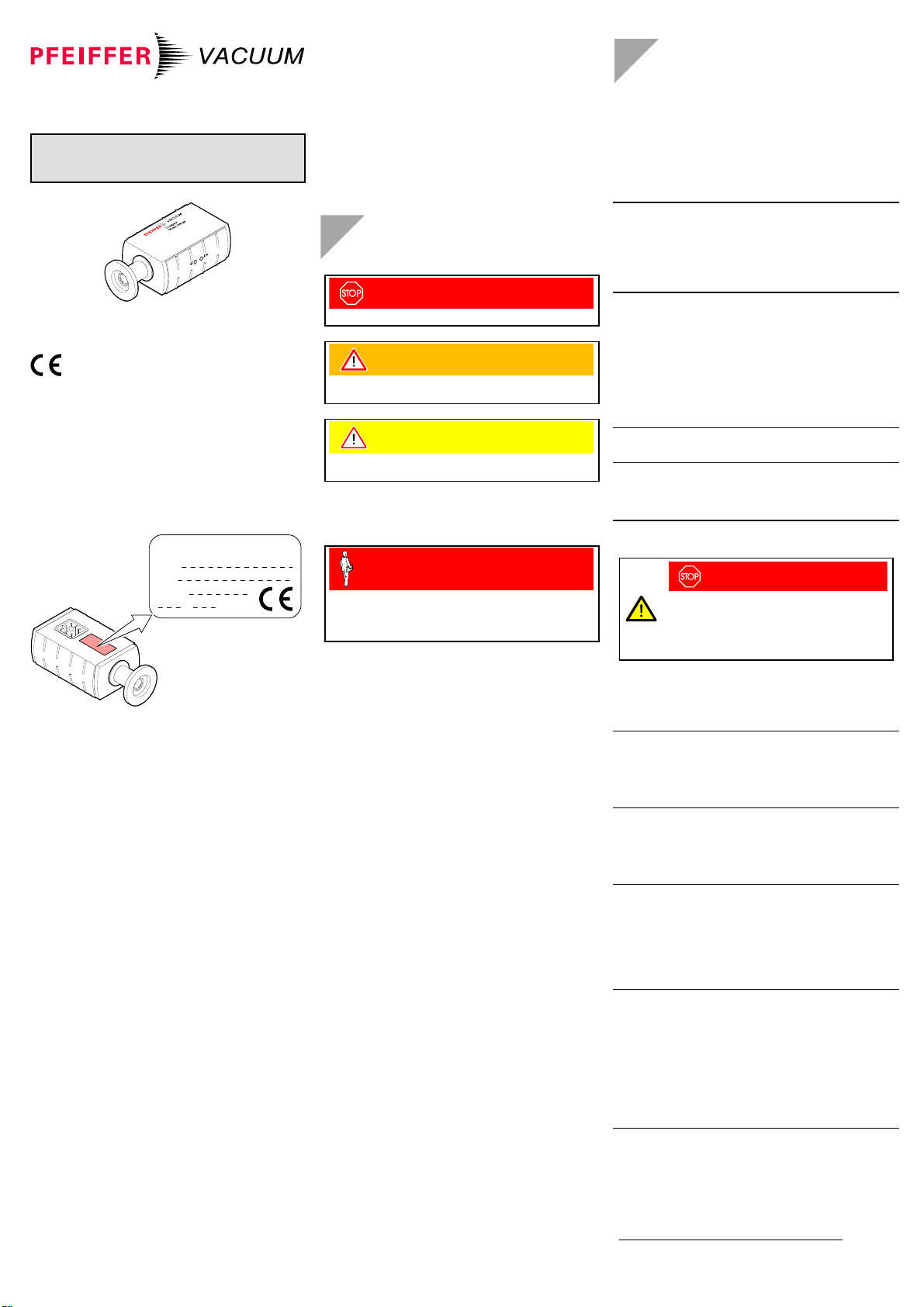
Product Identification
In all communications with Pfeiffer Vacuum, please specify
the information on the product nameplate. For convenient
reference copy that information into the space provided be-
low.
Typ:
No:
F-No:
V W
Pfeiffer Vacuum, D-35614 Asslar
Validity
This document applies to products with the following part
numbers:
PTR26750A (DN 16 ISO-KF 80 °C)
PTR26751A (DN 16 CF-R 80 °C)
PTR26752A (1/8" NPT 80 °C)
PTR26753A (8 VCR 80 °C)
PTR26760A (DN 16 ISO-KF 250 °C)
PTR26761A (DN 16 CF-R 250 °C)
PTR26800A (DN 16 ISO-KF 80 °C)
The part number (No) can be taken from the product name-
plate.
If not indicated otherwise in the legends, the illustrations in
this document correspond to gauges with DN 16 ISO-KF
vacuum connections. They apply other vacuum connections
by analogy.
We reserve the right to make technical changes without prior
notice.
All dimensions in mm.
Intended Use
The Compact Pirani Gauge TPR 265 has been designed for
vacuum measurement of gases in the pressure range of
5×10⁻⁴ … 1000 mbar.
The gauge can be operated in connection with a Pfeiffer
Vacuum controller for Compact Gauges or with another
evaluation unit.
Functional Principle
Over the whole measurement range, the measurement signal
is output as a logarithm of the pressure.
Trademarks
VCR® Swagelok Marketing Co.
Safety
Symbols Used
DANGER
Information on preventing any kind of physical injury.
WARNING
Information on preventing extensive equipment and envi-
ronmental damage.
Caution
Information on correct handling or use. Disregard can lead
to malfunctions or minor equipment damage.
Personnel Qualifications
Skilled personnel
All work described in this document may only be carried out
by persons who have suitable technical training and the
necessary experience or who have been instructed by the
end-user of the product.
General Safety Instructions
• Adhere to the applicable regulations and take the nec-
essary precautions for the process media used.
Consider possible reactions between the materials and the
process media.
Consider possible reactions (e.g. explosion) of the process
media due to the heat generated by the product.
• Adhere to the applicable regulations and take the nec-
essary precautions for all work you are going to do and
consider the safety instructions in this document.
• Before beginning to work, find out whether any vacuum
components are contaminated. Adhere to the relevant
regulations and take the necessary precautions when
handling contaminated parts.
Communicate the safety instructions to all other users.
Liability and Warranty
Pfeiffer Vacuum assumes no liability and the warranty be-
comes null and void if the end-user or third parties
• disregard the information in this document
• use the product in a non-conforming manner
• make any kind of interventions (modifications, alterations
etc.) on the product
• use the product with accessories not listed in the product
documentation.
The end-user assumes the responsibility in conjunction with
the process media used.
Gauge failures due to contamination, as well as expendable
parts (filament), are not covered by the warranty.
Technical Data
Measurement principle thermal conductance accord-
ing to Pirani
Measurement range
(air, O2, CO, N2)5×10⁻⁴ … 1000 mbar
Accuracy ≈10% of measured value in
range 1×10⁻³ … 100 mbar
(outside this range up to
factor 2)
Repeatability ≈2% of measured value in
range 1×10⁻³ … 100 mbar
Output signal
(measurement signal)
Voltage range
Measurement range 0 … ≈+10.3 V
+2.2 … +8.5 V
Voltage vs. pressure logarithmic, 1.0 V / decade
Error signal <0.5 V (filament rupture)
Output impedance 2×10 Ω
Minimum loaded impedance 10 kΩ, short-circuit proof
Response time
PTR26750A
PTR26751A
PTR26752A
PTR26753A
PTR26760A
PTR26761A
PTR26800A
≈10 ms
≈10 ms
≈10 ms
≈10 ms
≈10 ms
≈10 ms
≈500 ms
Gauge identification resistance 3.0 kΩreferenced
to supply common
Adjustment
Potentiometer <HV>
Potentiometer <ATM> adjustment under 10-4 mbar
adjustment at atmospheric
pressure
Supply
DANGER
The gauge may only be connected to supply and
evaluation units that conform to the requirements
of a grounded protective extra-low voltage
(SELV-E according to EN 61010). The connec-
tion to the gauge has to be fused 1).
Supply voltage at the gauge +14 … +30 VDC
(ripple ≤1 Vpp)
Power consumption ≤1.5 W
Fuse required 1) ≤1 AT (slow)
Electrical connection Hirschmann appliance con-
nector, type GO 6, 6 poles
Sensor cable 5 poles plus shielding
Cable length ≤150 m (5×0.25 mm2)
≤200 m (5×0.34 mm2)
Grounding concept →"Electrical Connection"
Vacuum connection
to signal common connected via 10 kΩ
(voltage difference ≤±50 V)
Supply common
to signal common conducted separately, for
differential measurement
Materials exposed to vacuum
Vacuum connection
Filament
Feedthrough
Baffle (only version
DN 16 ISO-KF)
Other materials
stainless steel
W
glass
stainless steel
Ni, Cu, NiFe
Internal volume
PTR26750A
PTR26751A
PTR26752A
PTR26753A
PTR26760A
PTR26761A
PTR26800A
≈2 cm3
≈2 cm3
≈2 cm3
≈2 cm3
≈10 cm3
≈10 cm3
≈2 cm3
Admissible pressure ≤10 bar (absolute) limited to
inert gases
1) Pfeiffer Vacuum controllers fulfill these requirements.