manuals.online logo
Brands
  1. Home
  2. •
  3. Brands
  4. •
  5. PH SVESIS
  6. •
  7. Smoke Alarm
  8. •
  9. PH SVESIS PHS102DS Quick start guide

PH SVESIS PHS102DS Quick start guide

TYPICAL WIRING DIAGRAM
Figure 1(a) shows the typical wiring diagram of the 2-
wire multiple-station smoke detector system.
INITIATING
LOOP
EN54 LISTED
COMPATIBLE
CONTROL
PAN EL
+
-
FIRST DETECTOR BASE LAST DETECTOR BASE
E
O
L
RESISTOR
5
252
61 34 61 34
+-+
REMOTE
INDICATOR
CLASS A OPTIONAL WIRING
NOTE: IF REMOTE I ND IC
A
TOR IS NOT USED. POL
A
RIT
Y
TO DETECTOR M
A
Y
BE RE
V
ERSED.
-
DO NOT PLACE LINKS BETWEEN THE WIRING POSITIONS
OF TERMINALS 2 AND 5 TO PROVIDE POWER
SUPERVISION
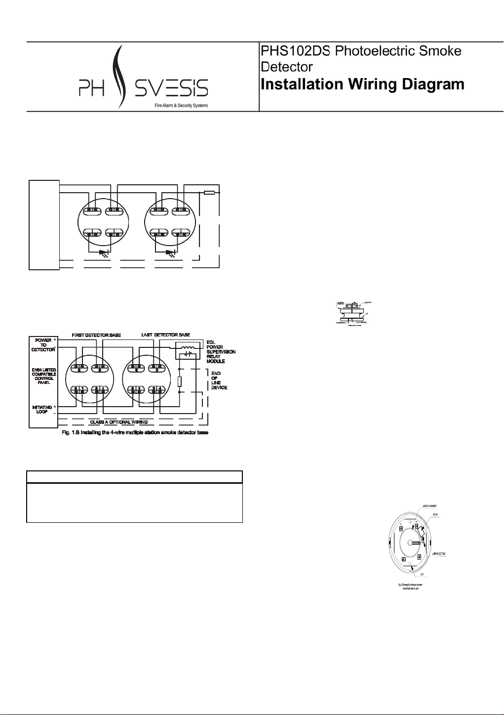
Figure 1(b) shows the typical wiring diagram of the 4-
wire multiple-station smoke detector system.
DO NOT PLACE LINKS BETWEEN THE WIRING POSITIONS
OF TERMINALS 2 AND 5 TO PROVIDE POWER
SUPERVISION
WARNING
TO PREVENT DETECTOR CONTAMINATION AND
SUBSEQUENT WARRANTY CANCELLATION, THE
SMOKE DETECTOR MUST REMAIN COVERED UNTIL
THE AREA IS CLEAN AND DUST FREE.
INSTALLING THE BASE
1. To ensure proper installation of the detector head to
the base, all the wires should be properly addressed at
installation:
(A) Position all the wires flat against terminals.
(B) Fasten the wires away from connector terminals.
2. If you use a jumper wire to connect the poles of
terminal 2 and 5 when testing the detector loop
continuity, be sure to remove the jumper wire prior to
the installation of the detector head.
3. The end-of-line device shown in fig. 1(a) and 1(b)
should be compatible with the control unit. The end-of-
line supervisory relay used should be rated for the DC
power voltage used.
4. Open area smoke detectors are intended for mounting
on a ceiling or a wall in accordance with the fire
standard in your country.
5. The base of the smoke detector can be mounted
directly onto an electrical junction box such as an
octagonal (75mm, 90mm or 100mm), a round (75mm),
or a square (100mm) box without using any type of
mechanical adapter.
INSTALLING THE HEAD
1. Align the components as shown in Figure 2.
2. Mate the detector head onto the base and twist
clockwise to secure it.
3. Do not install the detector head until the area is
thoroughly cleaned of construction debris, dusts, etc.
The maximum number of smoke detector installed in
the same loop is 30 units.
Fig. 2 Mating detector head onto base
ADJUSTING THE RELAY FOR NO/NC
The normal condition for the relay is “normally open”
(NO).
1. To adjust the normal condition of the relay to “normally
closed” (NC), insert a screwdriver into the rectangular
hole located on the side between the front cover and
base and rotate to remove the front cover.
2. Refer to figure 3. There is a jumper head next to the
relay on the PCB. Remove the jumper head and reinsert
it in the NC position.
3. Carefully replace the front cover.
Relay contact rating:
1A@30VDC,
0.5A@125VAC.
TESTING
1. All the alarm signal services, releasing device and
extinguisher system should be disengaged during the
test period and must be re-engaged immediately at the
conclusion of testing.
2. After energizing the detector head for approximately
one minute, check to see the indicator green LED
Fig. 3 Schematic of detector structure
When front cover is open.
flashing once every 3~5 seconds. If green LED fails to
flash, it indicates the non-functioning of the detector or
faulty wiring. Re-check the wiring or replace the
detector if necessary.
3. Allow smoke from a cotton wick or a test smoke
aerosol to enter the detector-sensing chamber for at
least 10 seconds. When sufficient smoke has entered
the chamber, the detector will signal an alarm, this
being visible by a continuous illumination of the LED.
Reset each detector and/or control unit before
attempting to test any additional detectors in the same
zone. If the alarm fails in this step, it indicates a
defective unit, which requires service.
NOT SUITABLE FOR INSTALLATION IN AREAS
WHERE AIR VELOCITIES EXCEED 300 ft/min
MAINTENANCE
The recommended minimum requirement for detector
maintenance consists of an annual cleaning of dust from
the detector head by using a vacuum cleaner cleaning
program should be agreed to the individual environment
in conformance with NFPA-72A standard.
CAUTION: DO NOT ATTEMPT TO DISASSEMBLY OF
THE FACTORY SEALED SMOKE DETECTOR. THIS
ASSEMBLY IS SEALED FOR YOUR PROTECTION AND
IS NOT INTENDED TO BE OPENED FOR SERVICING BY
USERS. OPENING THE DETECTOR HEAD WILL VOID
THE WARRANTY.
REFERENCE TO THE TECHNICAL BULLETIN ISSUE NO.
SDWD19112019, Ver. 1.00
SPECIFICATION
Model 2/4
wire
Ther
mal
Voltage
DC
Standby
Current
(Max.)
Alarm
Current
(Max.)
Surge
Current
(Max.)
Star-Up
Time
(Max.)
Permissible
Current
(Max.)
Frequency Alarm
Sound level
Alarm contact Base model
SD002-2 2 28/12V 90μA70mA120μA 60 Seconds 80mA 3-5 Seconds - P/N772912
LIMITED WARRANTY STATEMENT
PH-SVESIS S.A. represents that this product is free from defects in material and workmanship. And it will repair or
replace any product or part thereof which proves to be defective in workmanship or material for a period of twelve (12)
months from the date of purchase but not to exceed eighteen (18) months after shipment by the manufacturer. For a full
description of PH-SVESIS S.A.’S LIMITED WARRANTY, which, among other things, limits the duration of warranties of
merchantability and fitness for a particular purpose and excludes liability for consequential damages. Please read the
entire LIMITED WARRANTY on the PH-SVESIS S.A. quotation. Acceptance of order and/or original invoice which will
become part of your sales agreement. Please contact PH-SVESIS S.A. TECHNOLOGY directly for a return merchandise
authorization (RMA) number before returning goods to the factory. Shipment must be prepaid and PH-SVESIS S.A. will
repair or replace your returned detector.
69th Klm, N.R. Athinon-Lamias, Vrises Ritsonas – Viotia 34100, Greece
Call center: +30 210 28 55 000
info@phsvesis.com phsvesis.con
Document Part Number: PHS102DS-IM
version 1.0, revision 0 - NOVEMBER 2019

Popular Smoke Alarm manuals by other brands

König Electronic SEC SA30 manual

König Electronic

König Electronic SEC SA30 manual

Smoke hollow 44241G2 Assembly & operation

Smoke hollow

Smoke hollow 44241G2 Assembly & operation

Fire-Lite Alarms BG-12LXSP manual

Fire-Lite Alarms

Fire-Lite Alarms BG-12LXSP manual

Owon SD324 quick start guide

Owon

Owon SD324 quick start guide

Xtrails VESDA-E VEP-A10-P Product guide

Xtrails

Xtrails VESDA-E VEP-A10-P Product guide

System Sensor 6500E Installation and maintenance instructions

System Sensor

System Sensor 6500E Installation and maintenance instructions

Greystone DH100ACDCPA Installation and Maintenance

Greystone

Greystone DH100ACDCPA Installation and Maintenance

Argus Security Taurus TW-DO-01 quick start guide

Argus Security

Argus Security Taurus TW-DO-01 quick start guide

LST FC600/O Specification sheet

LST

LST FC600/O Specification sheet

First Alert 9120 Series user manual

First Alert

First Alert 9120 Series user manual

FireAngel Thermoptek ST-625 user manual

FireAngel

FireAngel Thermoptek ST-625 user manual

First Alert SCO2 user manual

First Alert

First Alert SCO2 user manual

Bosch FAS-420-TM installation guide

Bosch

Bosch FAS-420-TM installation guide

Kidde P4010ACSCO-WF-CA user guide

Kidde

Kidde P4010ACSCO-WF-CA user guide

Siemens FDOOT241-9 Technical manual

Siemens

Siemens FDOOT241-9 Technical manual

Smoke Canyon SC2045604-SC-00 Assembly, use and care manual

Smoke Canyon

Smoke Canyon SC2045604-SC-00 Assembly, use and care manual

System Sensor 1451 Installation and maintenance instructions

System Sensor

System Sensor 1451 Installation and maintenance instructions

Bentel Security FireClass FC400P manual

Bentel Security

Bentel Security FireClass FC400P manual

manuals.online logo
manuals.online logoBrands
  • About & Mission
  • Contact us
  • Privacy Policy
  • Terms and Conditions

Copyright 2025 Manuals.Online. All Rights Reserved.