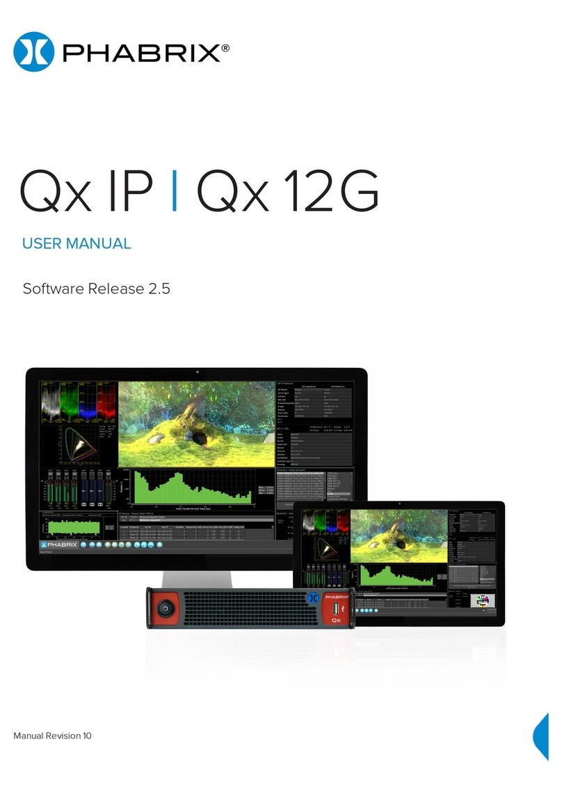
Phabrix PHQX-01E User manual

QX
G
PHABRIX Qx Operation Manual
Software Release 1.0.3
Manual Revision 4
PHABRIX®
®
broadcast excellence
Copyright © PHABRIX Ltd 2017
PHQX-01, PHQX-01E

PHABRIX Qx Operation Manual
Page II
About this Manual
Notice
The information in this document has been produced by PHABRIX Ltd with care and is believed to
be accurate. PHABRIX Ltd does not assume responsibility for loss or damage resulting from errors,
omissions or inaccuracies herein. This document is subject to change and revisions may be made and
issued to include such changes.
No part of this document may be reproduced, stored in a retrieval system or transmitted in any form
or by any means, electronic, mechanical, recorded or otherwise without the prior written consent of
PHABRIX Ltd.
Copyright © PHABRIX Ltd. All rights reserved. Software products licensed are owned by PHABRIX Ltd
and are protected by international treaty provisions and national copyright laws.
HDMI ® is the registered trademark of HDMI Licensing and is used within the document for identification
purposes only.
Revision
This manual is a revision controlled document. Any changes to any page content will be reflected in the
overall revision status of the whole manual.
Release Date Software Version Comment
1 23 Jan 2017 1.0.0.196 First release of manual
2 21 Mar 2017 1.0.1.227 Addition of Waveform, Vectorscope, HDMI
audio and new video standards
3 20 Jun 2017 1.0.2 Reference locking support with Output
offset adjustment. Input timing against
reference with Input Measurement Offset.
4 21 Aug 2017 1.0.3 HDR Heat-map, CIE 1931 x y Chart,
HDR/WCG additions for Waveform and
Vectorscope, and new PQ video standards.
REST API for remote control and
automation. CRC Analysis frame change
detection added.
PHABRIX® Limited
Omega House,
Enterprise Way,
Thatcham,
Berkshire
RG19 4AE
United Kingdom
phone + 44 (0)1635 873030

PHABRIX Qx Operation Manual
Page III
Getting Started
Package Contents
The shipping box should contain the following
PHABRIX Qx unit: PHQX-01 or PHQX-01E (with Physical Layer Analysis)
Power Supply Unit
Mains lead
General Safety
Avoiding Personal Injury
This instrument is designed for use by qualified personnel only.
No user serviceable parts are provided. Units should be returned to your local PHABRIX
agent for servicing.
The Operator should NOT remove the case from the unit.
Do not spill any liquid onto the unit or its power adaptor.
Power Supply
Make sure that the unit is connected to the correct power supply voltage. A power supply adaptor is
supplied with the unit which may be connected to any AC power supply between 100 and 240VAC at
50-60Hz. Only the supplied power adaptor should be used with the unit. Do not use a damaged AC
cable with the unit as it may cause a shock or fire hazard. Replacement AC cables are available from
your local PHABRIX agent.
How to upgrade software
New software releases will be made available regularly as the product develops.
Software downloads are approximately 100 MB and can be found in the Support area of the PHABRIX
website currently located at www.phabrix.com/support.asp
Download the file to any FAT32 formatted USB stick.
Make sure the unit is turned OFF before upgrading.
Insert the USB into the front panel USB port.
Press the start button TWICE in succession. The start button will glow pink when the upgrade procedure
begins. If the button doesnt glow pink then repeat the procedure.
The start button will flash several colours and the fans will be on full throughout the upgrade process.
Please wait approximately 4 minutes as the unit upgrades. It will automatically show the menu screen
when complete.

PHABRIX Qx Operation Manual
Page IV
Installation Environment
Operating Temperature
The unit should only be operated between 0 and 40 °Celsius. If the unit is operated
at a higher temperature there is a possibility of a fire hazard. If the temperature is
changed rapidly from a cold environment to a hot environment, moisture can be created
internally which can cause malfunction or damage the unit. Allow the unit to sit for 30
minutes without power applied to reduce any possibility of condensation. If the internal
temperature rises above 65°Celsius the unit will turn OFF automatically.
Input/Output Terminals
Do not connect the input or output BNC connectors to external power as this can damage the internal
circuitry and cause the unit to work incorrectly.
The BNC connectors fitted on this unit are 75Ω type which are not compatible with 50Ω plugs.
The use of 50Ω plugs will permanently damage the connectors on the unit. The use of
50Ω plugs is considered to be misuse of the equipment and will therefore invalidate the
unit’s warranty.
When Not In Use
Disconnect the unit from the power supply and AC power source when not in use.
Maintenance
Wipe the case gently with a soft cloth, lightly dampened with a neutral cleaning agent.
Remove the power supply from the unit and turn OFF before cleaning. Do not allow any
water or other liquid to enter the unit while cleaning.
RoHS Compliance
PHABRIX products are designed and manufactured using only RoHS compliant components and
materials. Therefore based on information provided by our suppliers, PHABRIX certifies that ALL
products that it manufactures are “RoHS-5” compliant and that they do not exceed the designated levels
of lead, cadmium, mercury, hexavalent chromium, polybrominated biphenyl (PBB) and polybrominated
diphenyl ether flame retardants (PBDE) legislated under the provisions of the “European Parliament
and Council Directive” on the “Restriction of the Use of Certain Hazardous Substances in Electrical
and Electronic Equipment (2011/65/EC)” and associated regulations collective known as the “RoHS
Regulations”.
Disposal of Equipment
This product is subject to the European WEEE (Waste Electrical and Electronic
Equipment) directive and should be disposed of according to the regulations of each
country.

PHABRIX Qx Operation Manual
Page V
Contents
Getting Started III
Package Contents....................................................................................................... III
General Safety............................................................................................................ III
Avoiding Personal Injury........................................................................................ III
Power Supply ........................................................................................................ III
How to upgrade software ........................................................................................... III
Installation Environment ............................................................................................IV
Operating Temperature .........................................................................................IV
Input/Output Terminals..........................................................................................IV
When Not In Use ...................................................................................................IV
Maintenance .........................................................................................................IV
RoHS Compliance.......................................................................................................IV
Disposal of Equipment ...............................................................................................IV
Icon display and meaning..........................................................................................VII
Overview 1
Start up....................................................................................................................... 1
Installation ............................................................................................................. 1
Analyser SDI connections....................................................................................... 1
Generator SDI connections ..................................................................................... 2
Powering up the Qx ................................................................................................ 2
Menu selection....................................................................................................... 2
Instrument Launch Menu........................................................................................ 2
Instrument Description 5
Generator - Configuration............................................................................................ 6
Pathological signal insertion................................................................................... 7
Output offset adjustment ....................................................................................... 7
Generator - Status....................................................................................................... 8
System IO (SDI)........................................................................................................... 9
Analyser - Configuration............................................................................................ 10
Stats - SDI In A, B, C, D............................................................................................. 11
Analyser - Picture ..................................................................................................... 12
Blanking Area ...................................................................................................... 12
HDR Heat-map (False Colour Overlay) ................................................................. 13
Transfer Curve and Colourimetry Overrides.......................................................... 14
Analyser - CIE Chart .................................................................................................. 14
Analyser - Waveform ................................................................................................. 15
Analyser - Vectorscope .............................................................................................. 16
Eye - SDI in A (PHQX-01E only) ................................................................................. 17
Jitter - SDI In A (PHQX-01E only) .............................................................................. 19
Analyser - Dataview................................................................................................... 20

PHABRIX Qx Operation Manual
Page VI
Timing and System Reference ................................................................................... 21
System Reference Lock ........................................................................................ 21
SDI A vs System Reference................................................................................... 21
Input Measurement Offset ................................................................................... 21
SDI Co-Timing....................................................................................................... 22
Analyser - Ancillary Status......................................................................................... 22
Analyser - Audio Meters............................................................................................ 23
Analyser - CRC Analysis............................................................................................. 24
Event Logging ........................................................................................................... 24
Network Status ......................................................................................................... 25
REST API Requests............................................................................................... 26
Time and NTP ........................................................................................................... 26
Specifications ............................................................................................................ 28
On-going Development.............................................................................................. 31
Supported SDI standards .......................................................................................... 32

PHABRIX Qx Operation Manual
Page VII
Icon display and meaning
Eye - SDI In A
Jitter - SDI In A
System IO (SDI)
Stats - SDI In A
Stats - SDI In B
Stats - SDI In C
Stats - SDI In D
Timing and System Reference
Analyser - Configuration
Analyser - Ancillary Status
Analyser - Audio Meters
Analyser - CIE Chart
Analyser - CRC Errors
Analyser - Dataview
Analyser - Picture
Analyser - Vectorscope
Analyser - Waveform
Generator - Configuration
Generator - Status
Event Logging
Network Status

PHABRIX Qx Operation Manual
Page 1
Overview
Start up
Installation
The rear of the unit shown above describes the connections and interfaces of the Qx.
Before turning on the Qx, make sure the following connections are in place:
The XLR power cable is inserted.
For instrument display connect a suitable 1920 x 1080 capable monitor to either the HDMI instrument
output or the SDI instrument output. The monitor output can be configured for 1080p60, 1080p59.94
or 1080p50 frame rates using ‘Display Options’ submenu of the ‘Instrument Launch Menu’.
For mouse and keyboard control, the two USB ports at the rear of the unit should be used.
Note: The following interfaces are temporarily unavailable in this release of software:
• SFP A and SFP B
• LTC In
• GPI I/O
• AES I/O
Analyser SDI connections
Analyser
The Physical Layer connection for eye and jitter outlined in red is the furthest right BNC with a red nut.
This provides the multi rate eye and jitter connection from HD-SDI to 12G-SDI.
There are four 12G-SDI capable input BNC’s for the analyser SDI IN A, B, C, D.
Up to four SDI inputs may be connected at any one time however the system will automatically
determine the signal set to analyse be it single link, dual link or quad link based on the SMPTE ST 352
packets present. The algorithm looks to ‘SDI IN A’ first and then determines the overall standard.
If the SMPTE ST 352 packets are known to be incorrect then the user has the option to select ‘Ignore
payload identifier packets (ST 352)’ in the ‘Analyser Configuration’ window.
Generator
12G/6G/3G/HD BNC x4
Analyser inputs
12G/6G/3G/HD BNC x4 (SFP+) MSA/NON-MSA 12Gbps
copper or bre, 10G Ethernet
Networking
10/100/1000BASE-T
2x USB 2.0 SDI instrument
output
Ref loop BNC x 2
HDMI instrument
output (to 1080p60)
Stereo Audio out, LTC in,
8x GPI I/O, 4x AES I/O
Power
10 - 18v
Micro USB (Factory service)
••
•••
• • • • • • • •
• •
•
•
•
• •
•
12G/6G/3G/HD Eye

PHABRIX Qx Operation Manual
Page 2
Generator SDI connections
The generator provides up to four SDI output signals which must form part of the same video signal set
e.g. 12G payload using four 3G-SDI outputs or 12G payload using two 6G-SDI signals.
‘SDI OUT A’ is always present and carries the first signal in the group. ‘SDI OUT B’ is active for dual link
standards and ‘SDI OUT C’ and ‘SDI OUT D’ are active for quad link standards.
Powering up the Qx
When the ‘Power Button’ on the Qx is first pressed, the unit fans will cycle for 20-30 seconds at high
speed as the system boots then settle to their normal operating speed.
Menu selection
The following menu screen will be displayed after power up:
To activate the ‘Instrument Launch Menu’ left click the PHABRIX symbol on the ‘Instrument Bar’
To hide the ‘Instrument Bar’ left click within its blank area
Bringing the cursor to the bottom of screen re-enables the ‘Instrument Bar’
Instrument Launch Menu
•
Power Button
•
USB port

PHABRIX Qx Operation Manual
Page 3

PHABRIX Qx Operation Manual
Page 4
As each instrument is selected, an icon will be placed on the ‘Instrument Bar’. The instrument and icon
will be assigned a colour. Each icon will glow in the assigned colour to indicate if it is part of a ‘group’ of
instruments related to analyser, generator, or system.
Instruments automatically group by colour. If one instrument is placed next to another then the border
will outline all instruments of a common group in contact with each other to aid group recognition.
Each instrument also has a sub menu. The sub menu is activated by right clicking the mouse in the
window enabling a drop down configuration menu. Click and drag on the grey bar at the top of the
sub menu to move it. In addition to window specific commands, the option to ‘Close’ the instrument is
provided in its sub menu.
Double clicking within a window will cycle through a set of standard instrument sizes. In many cases the
size of a window can be further adjusted to suit requirements. Click and drag on an instrument’s surface
to reposition the instrument.

PHABRIX Qx Operation Manual
Page 5
right click mouse for additional
drop down menus
Example of drop down menu on right mouse click:
211 mm
249.3 mm
44 mm
9.815 " 1.732 "
8.307 "
211 mm
249.3 mm
44 mm
9.815 " 1.732 "
8.307 "
211 mm
249.3 mm
44 mm
9.815 " 1.732 "
8.307 "
211 mm
249.3 mm
44 mm
9.815 " 1.732 "
8.307 "
Connect
generator to
analyser
211 mm
249.3 mm
44 mm
9.815 " 1.732 "
8.307 "
SDI OUT
(Generator)
SDI IN
(Analyser)
Instrument Description
The guide that follows is intended as an introduction to the menu selection and the tool-set. The Qx has
the advantage of being a generator and an analyser so this tour of the product will be using both tool-
sets simultaneously.
For this guide we will assume that you have connected the unit to itself as shown in the following
diagram.

PHABRIX Qx Operation Manual
Page 6
Generation
Generator - Configuration
The ‘Generator Configuration’ window is used to select the generator video standard and test pattern.
Once selected the new test signal is loaded by pressing the ‘Generate’ pane.
Note: In this software revision the generator takes approximately 8 seconds to load after which the eye
and jitter toolset will be enabled. During this period all other analyser functions are disabled.
Right clicking anywhere within the generator window brings up a configuration menu.
To simplify selection the generator standards list may be filtered using the following settings:
• Filter video standard list > Frame Rate > [No filter, 23.98, 24, 25, 29.97, 30, 47.95, 48, 50,
59.94, 60]
• Filter video standard list > Colour Format > [No filter, YCbCr:422, YCbCrA:4444, RGBA:4444,
YCbCr:444, RGB:444, YCbCrA:4224
• Filter video standard list > Bit depth > [No filter, 10, 12]
• Filter video standard list > Active Lines > [No filter, 720, 1080, 2160]
• Filter video standard list > Sub Image Format > [No filter, Single Image, square division, 2
Sampl...erleave]
• Filter video standard list > Level > [No filter, A, B]
• Filter video standard list > Combined SDI rate > [No filter, 1.5G, 3G, 6G, 12G]
• Filter video standard list > Source image width > [No filter, 1280, 1920, 2048, 3840, 4096]
• Filter video standard list > Interlace > [No filter, progressive, interlaced, segmented]
• Filter video standard list > Link Count > [No filter, 1, 2, 4]
• Filter video standard list > Transfer Curve > [No filter, SDR-TV, PQ]
Filters are removed by selecting in menu:
• Filter video standard list > Clear filters
Generator toolset border colour selection is provided for clear identification:
• Generator tools colour select, [colour]

PHABRIX Qx Operation Manual
Page 7
Colour selection is via the HSV tool shown above using two cursors. The left hand colour rectangle
allows selection of hue (horizontal) and saturation (vertical). The right hand vertical bar selects
luminance.
Pathological signal insertion
Pathological Signal Insertion is a powerful feature.
In addition to selecting a background test pattern a pathological pattern may be added as an overlay.
• Pathological insertion, [Enabled, Disabled]
Three types of pattern are supported:
• Pathological insertion, Pattern to overlay, [EQ, PLL, CheckField]
The amount of pathological pattern may be configured to enable the user to verify how sensitive the SDI
link is to pathological conditions on the interface:
• Pathological insertion, Pairs to insert, [0 to 16384]
This control limits at the selected formats line length.
Note: Pathological signals are approved by SMPTE for use with HD and 3G level A standards only. For
3G level B, 6G and 12G-SDI interface formats pathological signals can still be used but are not approved
by SMPTE (as of February 2017). It is believed that inserting a full line of pathological signal in these
non-approved standards is too stressful a test for the SDI interface. No physical damage will occur but
the interface may exhibit reduced operating performance in the form of bit errors.
Output offset adjustment
A signal can be generated with a fixed offset relative to the system reference.
Offsets can be entered in temporal or spatial terms:
• Output offset adjustment > Offset Type > [Time, Lines And Pixels]
Selecting ‘Time’ reveals a drop down field where the timing offset can be set in microseconds:
• Output offset adjustment > Offset Type > Time > Output Time Offset > [0.00, +/- 0.01, etc...]
Selecting ‘Lines And Pixels’ reveals drop down fields where the offset can be set in these terms:
• Output offset adjustment > Offset Type > Lines And Pixels > Output Line Offset > [0 to +/-
(Total no. of Lines for current standard -1)]
• Output offset adjustment > Offset Type > Lines And Pixels > Output Pixel Offset >[0 to +/-
(Total no. of Pixels per Line for current standard -1)]
Generator offset is removed by selecting in menu:
• Output offset adjustment > Clear offsets

PHABRIX Qx Operation Manual
Page 8
Generation
Generator - Status
The ‘Generator - Status’ menu shows the generator pattern selected and confirms the SDI OUT A, B,
C or D presence and Sub Image mapping information. This window is status only, there are no user
configurations.

PHABRIX Qx Operation Manual
Page 9
System
System IO (SDI)
Due to the complexity of the UHDTV standards, PHABRIX has introduced innovative ways of displaying
status. This however does involve the information being displayed across several instruments. The
‘System IO (SDI)’ window has been designed as a quick view of the signal inputs and outputs attached to
the Qx.
Active SDI inputs and outputs are indicated by the coloured connectors. Greyed out connectors indicate
signals not present. The colour of the connectors corresponds to the colour of the instrument borders
and instrument icons to aid recognition.
The presence of external reference and its standard is also displayed graphically with a coloured
connector. If the system is set to lock to the external reference and a stable lock has been achieved, then
the inner ring of the EXT REF BNC pictured will be highlighted in Grey.
• BNC image: [Grey (reference connected), Red (error with reference), Black (no reference
connected]
Note: The EXT REF BNC shows the status of external reference only; which is not neccessarily the system
reference. System reference is selectable in the ‘Timing and System Reference’ instrument.
Below the graphical connector display is a table showing SDI input and output status, and external
reference standard and status. The external reference field displays the following states:
• EXT REF: [No Signal, Unstable, 525/59.94, 625/50, etc...]
If external reference is not currently being used as system reference, its field text will display in yellow.
When external reference is the system reference,this table field text will be white.

PHABRIX Qx Operation Manual
Page 10
Analysis
Analyser - Configuration
The ‘Analyser - Configuration’ window controls the video standard being analysed. It lists the payloads
on the SDI input signals and highlights the ones used by the video standard being analysed.
The Payloads are identified primarily by ST-352 packets, if these are missing the signal stats will be
analysed and a best guess payload identifier will be listed.
Incorrect ST 352 packets are indicated in red within the ‘Analyser - Configuration’ window.
• Ignore Payload Identifier Packets (ST 352) > Checkbox [tick = ignore]
ST-352 packets can be ignored such that a best guess payload identifier is always used. Select the
“Ignore Payload Identifier Packets (ST-352)” option from the window’s menu.
• Analyser tools colour select > [colour]
Colour selection is via a HSV tool providing two cursors. The left hand colour rectangle allows
selection of hue (horizontal) and saturation (vertical). The right hand vertical bar selects luminance.

PHABRIX Qx Operation Manual
Page 11
Analysis
Stats - SDI In A, B, C, D
‘Stats - SDI In A’, B, C and D provide information to verify the format of the signals being analysed. A
video signal may be comprised of up to four separate SDI signals hence four separate windows.
Example 1 shows the display of data from a single 12G input on input A
Example 2 shows the display of data from a quad 3G input hence 4 separate video status windows

PHABRIX Qx Operation Manual
Page 12
Analysis
Analyser - Picture
The picture view shows the generator pattern currently being analysed by the Qx. The picture window
may default to full screen - simply right click to change the picture to SMALL or MEDIUM. Right click the
mouse to select MOVE to reposition the picture anywhere on the display.
The instrument’s right click submenu provides various setting, including the ability to confidence monitor
multi-sub-image video signals:
• Per Sub-Image Decimation > [Disabled, Enabled]
With this setting enabled, sub-images are decimated individually and recombined, allowing detection of
significant errors in individual sub-images (2SI only).
Note: The above setting will be available soon in a future software release.
Blanking Area
By right clicking with the mouse the operator can also enable ‘Show Blanking’. This will offset the picture
to the right revealing the blanking area.
• Show Blanking > [Disabled, Enabled]
Note: ‘Show Blanking’ is not available for multiple sub-image video standards as the active picture is
separated from the blanking regions during active picture reconstruction.

PHABRIX Qx Operation Manual
Page 13
HDR Heat-map (False Colour Overlay)
A false colour overlay can be applied to the picture view, to highlight areas of the image that are of
particular luminance.
The picture can be displayed in greyscale. If enabled at the same time as ‘False colour highlighting’,
all image elements outside of the enabled false colour overlay luminance range(s) will be displayed in
greyscale mode; leaving the false colour highlight elements to stand out more:
• Greyscale mode > [Enabled, Disabled]
A scale with numeric and graphic display of the luminance range(s) of the overlay in use, is available:
• False Colour Overlay Scale > [Enabled, Disabled]
The required luminance units for the scale can be selected:
• Luminance Measurement > [Decimal Level, PQ Nits]
Different types of false colour overlay may be applied to clearly visualise different image details, and a
custom mode is provided to allow the creation of a modified or bespoke overlay:
• False colour ranges > False Colour Highlighting > [Disabled, PQ HDR, SDR All Bands, SDR
Shadow, SDR Skin Tones, SDR Highlights, Out of Range, Custom]
The range(s) and colours of a selected false colour overlay can be modified by adjusting the 7 overlay
bands. Up to 7 distinct ranges can be simultaneously enabled in a single overlay. If adjusted, the new or
modified overlay will be designated as the ‘Custom’ overlay type.
This manual suits for next models
1
Table of contents
Other Phabrix Measuring Instrument manuals
Popular Measuring Instrument manuals by other brands

Deif
Deif MIB 8000 Designers handbook

PeakTech
PeakTech 2801 Operation manual

Sensorcon
Sensorcon CO Inspector product manual

RPB
RPB GX4 08-400 instruction manual

PCB Piezotronics
PCB Piezotronics W138A10/M038CY010EB Installation and operating manual

ICS Schneider Messtechnik
ICS Schneider Messtechnik IDM-60R quick start guide

Triplett
Triplett BR500 user manual

Laser Technology
Laser Technology LTI 20/20 TruSpeed user manual

Pfeiffer Vacuum
Pfeiffer Vacuum FullRange PBR 260 Short instructions

Dakota Digital
Dakota Digital MVX-2011 manual

Full Spectrum Laser
Full Spectrum Laser MUSE 3D Operation manual

Buckleys
Buckleys 6004-0093 operating instructions