Kenwood FC-758 User manual

©PRINTEDINJAPANB50-7728-00(N)
26408
INSTRUCTION
MANUAL
KENWOODCORPORATION
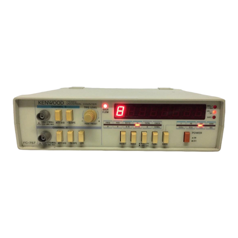
FREQUENCY COUNTER
FC-758
KENWOOD

CONTENTS
1.
GENERAL••3
2.SPECIFICATIONS•••4
3„PRECAUTIONSFORUSE7
4.PANELEXPLANATION8
4-1FRONTPANEL8
4-2REARPANEL• 13
4-3CASESURFACE16
5.OPERATINGPROCEDURES17
6.MEASURINGCONSIDERATIONS26
7.MAINTENANCE• 28
2

1.
GENERAL
The
FC-758
isa
multi-functional
counter.Itcanbe
used
tomeasureperiodsandtocounteventinputs(event
total
count)aswellastomeasurefrequenciesofupto
1.3GHz.
The
FC-758
counterhastwo
input
channels:ChannelA
andChannelB.
Channel
A isdesignedasan
input
circuitterminated
with
a 1.2Megaohmresistorandusedtomeasure
frequencies
from
5 Hzto100MHz.
Channel
B isdesignedasan
input
circuitterminated
with
a BOohtnresistorandusedtomeasurefrequencies
from
80MHzto1.3GHz.
The
FC-758
counter
outputs
measurementdatatoa
high-brightnessand
8—digit
LEDdisplay.Itsdisplay
resolutionis0.1Hz(MAX.)atupto10MHz.The
display
function
enablesthe
users
tocontinuethere
datameasuringoperationsona 'LookandGo'
basis.
Use
ofthis
product
wouldbeanadvantageinmeasur-
ingthefrequenciesintherelativelylowfrequencyrange
because
a periodmeasuring
function
(unit:microseconds)
andaneasily-controlledevent
total
count
function
are
supported.
Note
that
thisevent
total
countcanbe
controlledexternally
with
rear-panelgatesignalor
through
front-paneloperations.
The
FC-758
isprovided
with
a self-checkfunction.
The
function
enablestheusertocheckandconfirm
majormeasurementfunctions.
The
paneldisplay
portion
has
several
easy-to-use
LED
displayfunctionssuchasa leading-zero
blankingfunction,measurement
unit
displayfunction,
gateactivemodedisplayfunction,andover-range
display(overflowindication)function.
The
FC-758
uses
a highlystablecrystaloscillatoras
its
time
base,
The
time
base
timercancontinuestable
oscillationevenwhenthepowersupplyvoltage
fluctuatesorinhardtemperatureenvironment.Asa
result,high-accuracymeasurementoperationsremain
unaffected.
The
FC-758
counterhastheabovefunctions.
This
means
that
itisa highlyfunctionalfrequencycounter
with
high
accuracyand
that
itcanhelpdevelopersand
designers
aswellas
production
lineworkersand
servicingpersonnel
with
theirwork.
3

2.
SPECIFICATIONS
[Frequency
Measurement(ChannelA)]
MeasurementRange
kHz
mode:5Hzto10MHz
MHzmode:5Hzto100MHz
Accuracy
±ReferenceTimeAccuracy
±1 count
Resolution
kHz
mode:0.1Hzto100Hz
MHzmode:
1
Hzto1000Hz
CountingTime
(Gate
Time)
0.01s,
0.1s,1.0s,10.0s
Unit
kHz,
MHz
[
FrequencyMeasurement(ChannelB)J
MeasurementRange 80MHzto1.3GHz
Accuracy
±ReferenceTimeAccuracy
±1 count
Resolution
Prescale:
10Hzto10kHz
CountingTime
(Gate
Time)
0.027s,
0.27s,2.7s,27s
Unit MHz
[PeriodMeasurement(A)]
MeasurementRange 0.285/<sto200ms(5Hzto3.5
MHz)
Accuracy
±
1
count± ReferenceTime
Accuracy
± TriggerError*
Resolution
100ps
to
100
ns
Unit MS
Minimum
Pulse
Width
142.5
ns
Magnification
(Gate
Time)
X1,
X10,x100,X1000
*[ TotalizeMeasurement(A)]
MeasurementRange
5Hz
to10MHz
MaximumTotal
Count
0to99,999,999
Control
Method
Reset/Hold
control
from
the
flont
panel.Alwaysactive
exceptforthe
case
wherethe
Start/Stop
input
terminallevel
is
'InActive(activehigh).
4

[input
Characteristics(ChannelA)J
FrequencyBand
Width
5Hz
to100MHz(Coupling:AC
coupling)
Sensitivity(sinewave) kHzmode:20mVr.m.s.
(5Hz
to10MHz)
MHzmode:20mVr.m.s.
(5Hz
to30MHz)
50mVr.m.s.
(30MHzto100MHz)
Impedance
40pF
or
less
Maximum
Input
Voltage
125Vr.m.s.
at400Hz
Attenuation
xl
(1/1),
x10(1/10)
Low
Pass
Filter
100kHz,
-3dB
[
Input
Characteristics(ChannelB)j
FrequencyBand
Width
80MHzto1.3GHz(Coupling: AC
coupling)
Sensitivity(sinewave) lOmVr.m.s.(80MHzto600MHz)
25mVr.m.s.(600MHzto1.0GHz)
50mVr.m.s.(1.0GHzto1.3GHz)
Impedance
50a
Maximum
Input
Voltage 1.5Vr.m.s.
[ReferenceOscillator]
OscillationFrequency
Crystal
Oscillation10.0MHz
(Channel
A : 5Hzto100MHz)
Crystal
Oscillation3.90625MHz
(Channel
B : 80MHzto1.3GHz)
Stabilization
(TenperatureFactor,
Aging
Rate)
3x10
~6/0to40°C(10.0MHz)
1X10'6/0
to40°C(3.90625MHz)
5x10"7/
Month
(10.0MHz)
2X10"7/
Month(3.90625MHz)
[DisplayFunction]
Display
Eight-digit
7-segmentLED
DisplaykHz//*s,MHz,
GATE,
OVER
FLOW
FunctionsDisplay
kHz,
MHz,CHB,PER,
TOTAL,
CHECK
CountingTime
(Gate
time)
CH
A :0.01s,0.1s,1.0s,10s
CH
B : 0.027s,0.27s,2.7s,27s
[Self-cheekFunction]
Display Displaya
count
valueofthe
internal
time
base
timer
(10.0MHz).
5

CountingTime
(Gate
time)
0.01s,
0.1s,1.0s,10s
Resolution 0.1Hzto
100
Hz
[General
RequirementsJ
Power
Supply
Voltage
Power
Comsunption
100/120/220/240V
± 10%(Max
250V),
50/60Hz,
20VA
Within
Specifications
Temperatureand
Humidity
23°C±5°C,70%RH
OperatingTemperature
andHumidety 0°Cto40°C,80%RH
Dimentions
240(W)x64(H)xl90(D)mm
[Max.260(W)x70(H)x210(D)mm]
Weight
1
8kg
Accessories
InstructionManual1
Power
SupplyCable1
Replacement
Fuse
1
*Triggererroristyp[cal!y± 0.3%ofreadingdivided
bythenumberofcyclesaveraged,for
input
signals
havingbetterthan40dBS/N
ratio
andgreaterthan
lOOmVamplitude.
6

3.
PRECAUTIONS
FORUSE
a-
TurnofftheproductandthenconnectitwiththeAC
wall
outletbyusingthe
accessory
powercablecord.
Refer
tothemaintenancesectioninthisdocumentin
changing
thecurrentpowersupplyvoltagetoa new
level.
b.Theuseofthisproductunderthefollowingambient
conditonsisstrictlyprohibited:
Direct
exposuretothesunlight
High-temperatureandHigh-humidity
Mechanical
Vibrationand
ElectricalShock
c.
Themaximuminputterminalvoltage
levels
ofthis
counterareasfollows:
(Front
Panel)
Channel
A Input
Juck
: 125Vrms(at
400Hz)
Channel
B Input
Juck
: 1Vrms(at80MHzto1.36Hz)
(Rear
Panel)
TOTALIZE
INPUT
START/STOP
Input
Juck
: ±5V
d»
This
countercanstartitsoperationatthemoment
when
powerisapplied.However,wait30minutesto
give
ita warmandthenstartyourjobwithit.
Accurate
measurementwillbe
assured.
The
counterisinitializedasfollowswhenturned
on:
FUNC
switch: kHz/10MHzmode
GATE
switch:
0.27s/0.01s
kHz/p-
s display
LED:Active
Notethatthedisplayindicates"0"ifnosignalisinput
tothecounter.
7

4.
PANEL
EXPLANATION
4-1FrontPanel
®
POWER
ON-—./QFFJB.
Switch
(See
Figure1.)
The
POWER
ON
JUL/OFFM
switchisprovidedto
applypowertothiscounter.If
pressed
(
J«-),
the
counterwillbeturnedon.Ifpressedagain(JKL),
thecounterwillbeturnedoff.
©
GATE
LED
©
kHz/^s
IndicatorLED
The
kHz/i«sLEDindicatorisprovidedtoremind
theuserofthecurrentmeasurementdata
unit.
This
LEDindicatesthe
unit
ofthecurrent
measurementoperation.Ifthefrequencymeasurement
modehasactivated,itmeansthatthemeasurement
value
is
output
inkiloherz.TheLEDindicatesthat
themeasurementvalueisdisplayedinmicroseconds
ifa periodisbeingmeasuredortheself-check
modeisselected.
®MHzIndicatorLED
The
MHzLEDindicatorisprovidedtoremindthe
user
ofthecurrentmeasurementdata
unit.
This
LEDturnsonwhenthefrequencymeasurement
value
isdisplaedinMegaherz.
©DisplayLED
The
displayconsistsof
eight-digit
LEDs
indicatingallthemeasurement
values.
©
OVER
FLOW
IndicatorLED
The
OVER
FLOW
LEDisprovidedto
notify
the
user
thatanoverflowhasoccurred.
This
LEDblinkswhenanymeasurementdata
exceeds
thedisplayrange.
©
CHANNEL
B(80MHzto1.3GHz)Inputjuck
The
CHANNEL
B
input
juckisa prescale
input
juck
providedtoallowobjectsignalstoenterthecounter.
Ifthefrequencyofgreaterthan100MHzismeasured,
thisjuckisusedasthe
input
juck.
This
juckis
terminated
with
a resistorof50ohm.
This
input
juckcanbeusedtomeasurethefrequencies
intherangebetween80MHzand1,300MHz
(1.3GHz).
This
input
juckcanbealsousedtomeasurethe
frequencies
of
less
than100MHz.However,itis
recommendedthatChannelB beusedforthispurpose
8

Figure1.FrontPanel
3

because
itsresolutionfunctionsbetterthanthe
channel
A'sone.
®
CHANNEL
A(5Hzto100MHz)Input
Juck
The
CHANNEL
A
input
juckisprovidedtoallow
objectsignalstoenterthecounter.
Ifthefrequencyof
less
than100MHzismeasured,
every
kindofcycleismeasured,oreventinputs
are
counted,thisjuckisusedasthe
input.
This
juckisa BNCconnectorterminated
with
a
resistor
of1.2Megaohm.
Note:Ifa 50ohmsystemisconnectedtothis
counter,theChannelA Inputjuckneedstobe
terminated
with
a resistorof50ohm.
Please
keep
itinmind.
@
ATTx 10Switch
The
ATT(enuation)x 10switchisprovidedto
enable
theinternalATTenuatorcircuitoperation.
Ifthisswitchispressed(x10),the
input
signalto
channel
A isattenuated
into
1/10andthenreaches
thecounter.
Ifthisswitchispressedagain(x1),the
input
signal
tochannelA reachesthecounter
without
attenuation.
Notethatthisswitchcanworktogether
with
channel
A onlybutdoesnotaffectchannelB.
®LPFSwitch
The
LPFswitchisusedtoenabletheLow
Pass
Filter
circuitoperation.
Ifthisswitchis
pressed(JUL),
the
input
signalto
channel
A isforcedtoentera low
pass
filter
of
about100kHz.
Ifpressedagain( I,)fthe
input
signalreachesthe
counterdirectly.
This
LPFswitchdoesnotaffect
channel
B.
©
RESET
Switch
The
RESET
switchisprovidedtoclearthecounter
into
0.
This
switchcanwork,independentlyofany
operationmodeselectedby
FUNC
switch(13).
Ifthisswitchispressed(thecounterwillbe
reset
to0.
Ifthisswitchis
released(JR.),
a newmeasurement
willbestarted.
©HOLDSwitch
The
HOLDswitchisprovidedtoperformvarious
operationsshownbelow.NotethattheHOLD
switchfunctionsdependonoperationalmodes
10

selected
by
FUNC
switch@.
a.
InanymeasurementmodeotherthantheEvent
Input
TotalCountoperationmode:
Ifthisswitchispressed
(JBL),
thecurrent
measurementvalueindicatedbythedisplay
LEDs
is
'held'andthecounterisreset.
Ifpressedagain
(JHL),
a newmeasurement
will
bestarted.Thedisplayvaluebeing'held'isnot
until
thenewmeasurementiscomplete.
b.EventTotalCounter
(TOTAL/10
MHz)
Mode
:
Ifthisswitchispressed(_«&.),thecurrent
measurementvalueindicatedbythedisplay
LEDs
is
'held'andtheevent
total
countisterminated.
Ifpressedagain(_•_),a newcountingoperation
will
bestarted.
Note
that
TOTALIZE
INPUT
START/STOP
input
juck© shouldbe
left
'Open'
beforethenewcountingoperationisstarted,
operationisstarted.
@
FUNC
Switch/ModeIndicationLED
The
FUNC
switchisprovidedtoselectthedesired
operationalmode
from
theavailablemodes.
The
Mode
IndicationLEDisprovidedtoenablethe
user
toseethemeasurementmodecurrentlyinuse.
The
following
operationalmodescanbeselected
with
thisswitch:
a.
kHz/10MHz(frequency)measurementmode
The
kHz/10MHzmeasurementmodeisan
operationalmodeinwhichthisfrequency
countermeasuresthefrequencyofan
input
signalto
CHANNEL
A.Themeasurementdata
will
bedisplayedin'kHz'.
A
desiredresolutionvaluecanbeselected
with
GATE
switch@ .
Note
: Themaximumfrequencytobehandled
inthismeasurementmodeis10MHz.The
properrangeshouldbeusedaccordingto
input
frequencies
with
eachrangecharaceristics
fully
inmind.
b.MHz/100MHz(frequency)mode
The
MHz/100MHzmodeisanoperationalmode
inwhichthiscountermeasuresthefrequencies
of
input
signalstochannelA and
outputs
the
measurementdatatothedisplaysection.They
are
displayedinMegaHerz(MHz).
A
desiredresolutionvaluecanbeselected
with
GATE
switch@ .
11

Note: Themaximumfrequencytobehandledin
thismeasurementmodeis100MHz.Theproper
range
shouldbeusedaccordingtoinput
frequencies
with
each
rangecharacteristicsfully
inmind.
c.
CH
B/1.3GHz
(frequency
prescale)
mode
The
CH
B/OGHz
modeisanoperationalmode
inwhichthisproduct
measures
thefrequenciesof
inputsignalstochannelB andoutputsthemto
thedisplaysection.
They
aredisplayedin
MegaHerz
(MHz).
A
desiredresolutionvaluecanbeselectedwith
GATE
switch© .
d.
PER/0.3j«s
(PERIOD)
mode
ThePER/0.3/*s
modeisanoperationalmodein
which
thisproduct
measures
the
cycle
timesof
inputsignalstochannelA andthenoutputs
themtothedisplaysection.
They
aredisplayed
inmicroseconds.
A
desiredresolutionvaluecanbeselectedwith
GATE
switch© .
e.
TOTAL/10
MHz(eventinput
total
count)mode
The
TOTAL/10
MHzmodeisanoperationalmode
inwhichthisproductcountsthenumberof
channel
A input
cycles
andthenoutputs
each
countvaluetothedisplaycontinuously.
This
cycle
countanddisplayoperationscanbe
externally
controlledwiththegatesignalinput
tothe
TOTALIZE
INPUT
START/STOP
input
juck
ontherearpanelorthe
HOLD
switch
onthe
front
panel,
f.
CHECK/10MHz
Mode
The
CHECK/10MHz
modeisanoperationalmode
inwhichthisfrequencycounter
checks
internal
functions.
Ifthisself-checkmodeis
selected,
the
frequency
oftheinternaltime
base
timer(10MHz)
willbedisplayedbythe
8—digit
7-segment
LEDs.
Look
atthedisplayvaluetoseeifthisproduct
operates
normallyornot.
A
desiredresolutionvaluecanbeselectedwith
GATE
switch@ .
@
GATE
Switch/GATE
LED
TheGATE
switchisprovidedtoselecta desired
display
resolutionvaluefortheperiodmode
(PER/0.3us)
orthefrequencymode(MHz/100MHz,
kHz/10MHz,
orCH
B/1.3GHz)
startedby
FUNC

switch@ .
The
GATE
LEDisprovidedtoindicatethe
counteriscurrentlyactive.
Iftheswitchispressed,a newdisplayresolution
value
isselected.Thisoccursevery
time
whenthe
switchispressed.Thereare
four
displayresolution
values
available.Theyare:
0.01s,
0.1s,1s,10sforChannelA
0.027s,
0.27s,2.7s,27sforChannelB
Resolution
value
0.027s
0.27s
2.7s
27s
Resolution
value
0.01s
0.1s
1.0s
10s
Magnification
xl
xlO
X100
X1000
4-2
Rear
Panel(SeeFigure2.)
©
TOTALIZE
INPUT
START/STOP
Input
juck
The
TOTALIZE
INPUT
START/STOP
input
juckis
providedto
control
theevent
input
countoperation
mode.
The
event
input
countoperationisenabledifthe
input
signaltothisjuckbecomesactive(TTLlevel:
'H').
The
event
input
countoperationisforcedto
terminateifthe
input
signaltothisjuckbecomes
inactive(TTLlevel: 'L').Theevent
input
count
operationisalsodisabledifthisjuckisgrounded
tothe
chassis
ground.
13

Figure
2.RearPanel
14

@
Powersupplyvoltageselector
(LINE
VOLTAGE
SELECT)
The
powersupplyvoltageselectorisprovidedto
select
thesupplyvoltage
that
isappliedtothe
counter.
When
youchangethecurrentsupplyvoltage,
refer
tosection7-1'Maintenance'.
©Power
input
connector
The
power
input
connectorisprovidedfor
connectinga powercordtothecounter.Usethe
accessory
powercord.
@
Fuse
Holder
The
fuseholderisprovidedtoenabletheuserto
set
a
protection
fuseinthecounter.
For
the100V-or120V-powerrequirement,use
the0.25A/250Vslow-blowtype
fuse.
For
the220V-or240V-powerrequirement,use
the0.125A/250Vslow-blowtype
fuse.
When
youreplacethecurrent
fuse,
refertoChapter
7
'Maintenance'.
15

4-3
Case
Surface
@
Thereisanopeningonthe
case
surfacetoenable
theusertofine-adjustthe
TCXO
(standardoscillator).
This
adjustmentappliesto
both
oftheCHA
(10.0MHz)
andCHB (3.90625MHz)channels.
The
openingisnormallycovered
with
a rubbercap.
Iftheoscillatorneedstobefineadjusted,please
contactyourdealerrepresentative.
Figure
3.
Case
Surface
16

5.OPERATING
PROCEDURES
Every
timewhenyoustartusingthe
FC-758
Multi-
FunctionalCounter,lookattherearpanelandverify
thatthepowersupplyvoltageselectorsetting
indicatesthelevelofthesupplyvoltagetobeactually
applied.
1)
Connectthe
accessory
powercord
with
thepower
input
connector(inlet)oftherearpaneland
inserttheACplug
into
thenearby
outlet.
2)
Press
the
POWER
switch(
JHL).
Thecounterwillbe
turnedon.
3)
Read
carefullyChapter3 ' Notesonuse'(onpage7)
tohandlethisinstrumentcorrectly.
5-1FrequencyMeasurement
5-1-1.
FrequencyMeasurement
with
ChannelA
(5Hz
to100MHz)
(1)
Inputa targetsignal(tobemeasured)to
CHANNEL
A
input
juck®.
(2)
Select
eitherthekHz/10MHzmodeorMHz/100MHz
modebyusing
FUNC
switch@).
kHz/^s
LED(3)
orMHzLED® willbeturnedon.
Note: Themaximumallowablemeasurement
frequency
varies
dependingonthemeasurement
modes.
InthekHzmeasurementmode,upto
10MHz-frequencycanbeprocessedwhilethe
maximumfrequencythatcanbehandledinthe
MHzmodeis1.3GHz.
(3)
Select
a desireddisplayresolutionvalue
with
GATE
switch© .
(4)
Thefrequencyofthe
input
signalcurrentlybeing
measured
willbe
output
toDisplay©.
GATE
LED© blinksduringthemeasurement.
The
measurementvalueonthedisplaywillbe
updatedatthemomentwhenonemeasurement
intervalisover(whenthe
GATE
LEDbecomes
inactive).
(5)
Press
ATTx 10switch
(JBL.)
accordingto
input
signal
levels.
Iftheinternalattenuatorcircuitis
enabled,
input
signaltothe
CHANNEL
A pinis
attenuated
into
1/10beforereachingthecounter.
This
attenuatesnoise-superimposed
input
signals.
Inaddition,theattenuationcircuitpreprocessesa
signal
with
rathera highamplitude
into
a
reasonable
level.
Asa result,accuratecounting
is
assured.
17

(6)
Press
LPF(low
pass
filter)switch© (
JL)
to
eliminatenoisesignalcomponents.Iftheinternal
LPF
circuit
function
isenabled,the
input
signal
tothe
CHANNEL
A juckishandledfirstbythe
LPF
circuit(about100kHz)andthen
input
tothe
counter.Therefore,thecounterprocesses
input
signals
without
high-frequencynoisesonly.Asa
result,accuratelow-frequencymeasurementis
assured.
(7)
IfHOLDswitch© ispressed
during
frequency
measurement,thecurrentmeasurementvalueon
theDisplayisheldasitis.Iftheswitchisreleased,
a
newmeasurementcycle
will
bestarted.However,
themeasurementvaluecurrentlybeingdisplayed
will
remainunchanged
until
thenewmeasurement
cycle
iscomplete.Thatis,thedisplayvaluebeing
heldbytheHOLDswitchisupdatedbythe
output
value
from
thenewmeasurementoperation.
(8)
If
RESET
switch@ ispressed
during
frequency
measurement,themeasurementvalueonthe
Display
will
beresetto'0'.Ifpressedagain,a
newmeasurementcycle
will
bestarted.However,
themeasurementvalue
will
remain'0'
until
the
newcycleiscomplete.
5-1-2.
FrequencyMeasurement
with
CHANNEL
B
(80MHzto1.3GHz)
(1)
Input
a targetsignal(tobemeasured)to
CHANNEL
B prescale
input
juck®.
Note
: Themaximum
input
voltagetothisjuckis
1
Vrmsandits
input
impedanceis50ohm.ATTx
10
switch® cannotworktogether
with
thisjuck.
(2)
SelecttheCHB/OGHzmode
with
FUNC
switch
(3)
Selecta desireddisplayresolutionvaluebyusing
GATE
switch@ .
(4)
Thefrequencyofthe
input
signalcurrentbeing
measured
will
be
output
toDisplay©.
GATE
LED(2)blinks
during
thefrequency
measurement.
The
measurementvalueindicatedbytheDisplay
will
beupdatedatthemomentwhenone
measurementcycleiscomplete(whenthe
GATE
LED
becomesinactive).
Note
: Itmayhappentooccur
that
measurement
is
delayedorthedisplayisunstable.Inthis
case,
refertosection5-4' DisplayDescription'.
18

(5)
IfHOLDswitch© ispressed
during
frequency
measurement,thecurrentmeasurementvalueon
theDisplayisheldasitis.
Ifpressedagain,a newmeasurementcycle
will
bestarted.However,themeasurementvalue
currentlybeingdisplayed
will
remainunchanged
until
thenewmeasurementcycleiscomplete.
That
is,thedisplayvaluebeingheldbytheHOLD
switchisupdatedbythe
output
value
from
the
newmeasurementoperation.
(6)
If
RESET
switch© ispressed
during
frequency
measurement,themeasurementvalueonthe
Display
will
beresetto'0'.
Iftheswitchisreleased,a newmeasurement
cycle
will
bestarted.However,themeasurement
value
will
remain'0'
until
thenewcycleis
complete.
(7)
ATTx 10switch® andLPFswitch© are
helpless
intheprescale
input
mode.
5-2PeriodMeasurement
Intheperiodmeasurementmode,thecycle
time
of
each
input
signalismeasured.
The
cycle
time
finally
output
bythecounteristhe
average
ofallthe
cycles
measured.Thenumberof
cycles
tobemeasuredcanbe1,10,100or1000.
The
maximum
input
frequencyis3=5MHz.
(1)
Input
a targetsignal(tobemeasured)tothe
CHANNEL
A
input
juck.
(2)
Selectthe
PER/0.3us
(period)mode
with
FUNC
switch@ .
The
kHz/^s LED
will
turn
onindicating
that
the
measurementvalueisdisplayedinmicroseconds.
(3)
Selecta desireddisplayresolutionvalue
with
GATE
switch@ .
This
GATE
switchisusedto
specifythenumberof
cycles
percyclemeasurement.
As
alreadyexplained,thefinalcycle
time
output
is
theaverageofallthecycletimes.Thedisplay
resolution
LEDs
(fromtheleft)indicates1,10,
100
and1000.
(4)
Theaveragecycle
time
ofalltheperiodsmeasured
is
output
toDisplay©.
GATE
LED® blinks
during
theperiodmeasurement.
The
measurementvalueonthedisplay
will
be
updatedatthemomentwhenoneperiodmeasurement
is
complete(whenthe
GATE
LEDturnsoff).The
GATE
LED
blinking
maynotbeconfirmedbecause
19

itgetstoofastduetohigh-frequencysignal
measurement.
Note
: Itmayhappentooccur
that
measurement
is
delayedorthedisplayisunstable.Inthis
case,
refertosection5-4' DisplayDescription'.
(5)
Press
ATTx 10switch(_•*.)accordingto
input
signallevels.Iftheinternalattenuatorcircuitis
enabled,
input
signaltothe
CHANNEL
A juckis
attenuated
into
1/10beforereachingthecounter.
This
attenuatesnoise-superimposed
input
signals.
Inaddition,theattenuationcircuitpreprocessesa
signal
with
rathera
high
amplitude
into
a reasonai
level.
Asa result,accuratecountingis
assured.
(6)
Press
LPF(low
pass
filter)switch<©
(-ML)
to
eliminatenoisesignalcomponents.Iftheinternal
LPF
circuit
function
isenabled,the
input
signalto
the
CHANNEL
A juckishandledfirstbytheLPF
circuit(about100kHz)andthen
input
tothe
counter.Therefore,thecounterprocesses
input
signals
without
high-frequencynoisesonly.Asa
result,accuratelow-frequencymeasurementis
assured.
(7)
IfHOLDswitch© ispressed
during
period
measurement,thecurrentmeasurementvalueonthe
Display
isheldasitis.Ifpressedagain,a new
measurementcycle
will
bestarted.However,the
measurementvaluecurrentlybeingdisplayed
will
remainunchanged
until
thenewmeasurementcycle
is
complete.Thatis,thedisplayvaluebeingheld
bytheHOLDswitchisupdatedbythe
output
value
from
thenewmeasurementoperation.
(8)
If
RESET
switch© ispressed
during
period
measurement,themeasurementvalueontheDisplay
will
beresetto'0'.
Iftheswitchisreleased,a newmeasurementcycle
will
bestarted.However,themeasurementvalue
will
remain'0'
until
thenewcycleiscomplete.
5-3Event-InputTotalCountMeasurement
IntheEvent
Input
Totalmeasurementmode,the
total
numberofeventsgenerated
during
a fixed
certainperiodismeasured.
This
measurement
periodcanbesetbyusingthe
front
panelswitch
ortherearpanelgatesignal
input
juck.
The
signal
input
circuitandthecounterare
coupled
with
capacitance(AC),whichrequires
atleast5 eventspersecondtobegenerated.
20
Table of contents
Other Kenwood Measuring Instrument manuals

Kenwood
Kenwood HM-250 User manual

Kenwood
Kenwood DM-81 User manual

Kenwood
Kenwood FC-757 User manual

Kenwood
Kenwood VT-176 User manual

Kenwood
Kenwood FL-180 User manual

Kenwood
Kenwood VT-175 User manual

Kenwood
Kenwood VT-183 User manual

Kenwood
Kenwood FL-180A User manual

Kenwood
Kenwood FL-140 User manual

Kenwood
Kenwood VT-181 User manual