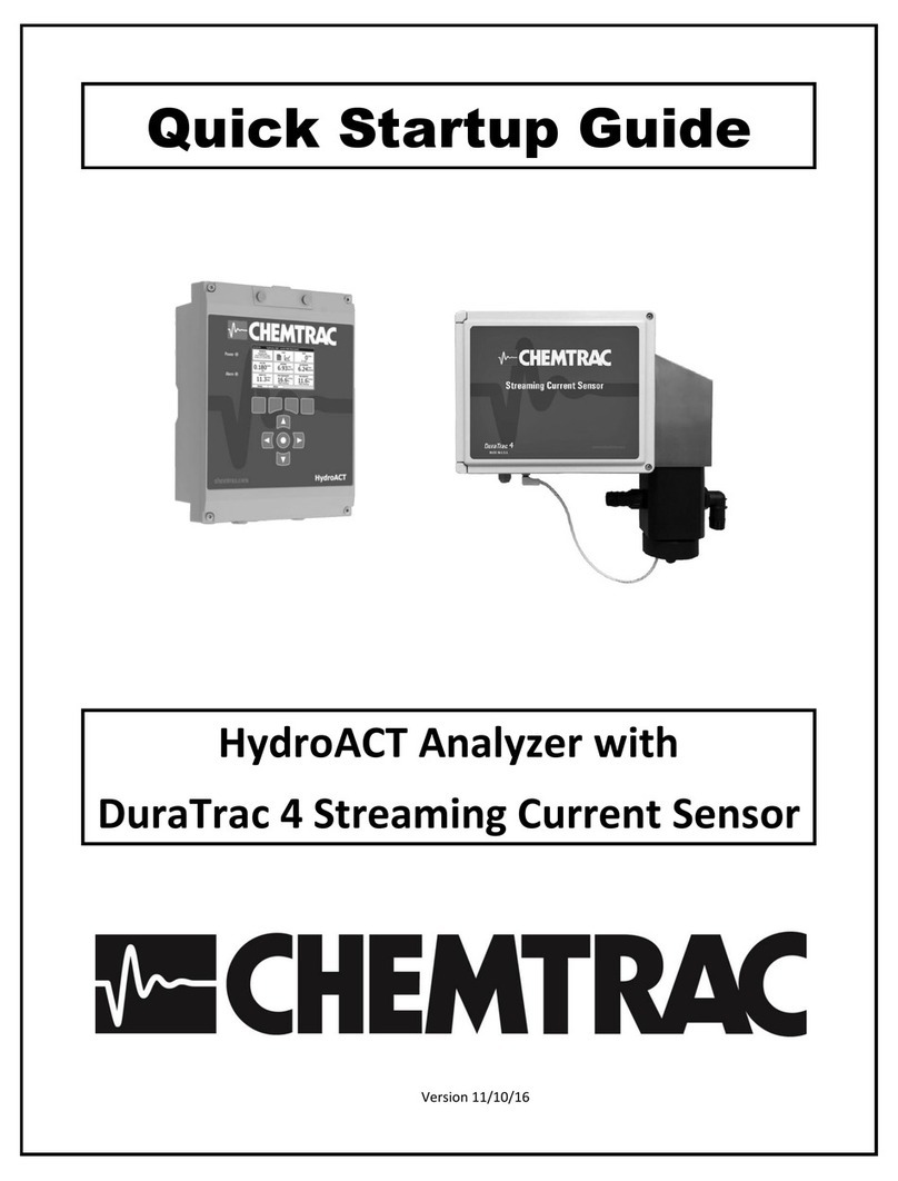
Chemtrac HydroACT User manual

Quick Start Guide
HydroACT Analyzer with
Free or Total Chlorine Sensor
Version 03/10/2020

2

3
Contents
Included Items............................................................................................................................................... 4
Installation Guidelines .................................................................................................................................. 4
Mounting Dimensions / Sample and Drain Line Connections ...................................................................... 5
Accessing Wiring Terminals .......................................................................................................................... 6
Chlorine Probe and Analog Output Wiring ................................................................................................... 7
Analog Output Setup..................................................................................................................................... 8
Relay Setup ................................................................................................................................................... 8
Assembling the Chlorine Probe ..................................................................................................................... 9
Proper Positioning of Probe into the Flow Cell Probe Chamber ................................................................ 10
Sample Flow Considerations ....................................................................................................................... 10
Drain Line Considerations ........................................................................................................................... 10
Calibration Procedure ................................................................................................................................. 11
Troubleshooting .......................................................................................................................................... 12
Safety Precautions
This Quick Start Guide is a supplement to the User Manual, and is intended to give an overview of the
product, accessories, and set-up prior to installation. The user is advised to review the full product
manual before the analyzer is connected to the power source, or any other sources of force or pressure
(for example, hydraulic or pneumatic), and started in operation. Failure to follow these precautions
could result in personal injury and damage to the equipment.
The HydroACT controller can be ordered with various other sensors and options which may not be
discussed in this quick start guide. Please contact Chemtrac with any questions.

4
Included Items
In addition to this Quick Start Guide the following items were included in the packaging. Notify Chemtrac of
missing items before disposing of any packaging material.
HydroACT Analyzer
Chlorine Probe
Probe Flow Cell
Probe Interconnect Cable (15 ft)
Membrane Cap
Electrolyte
Blue Abrasive Paper
HydroACT User Manual
Mounting Template for HydroACT Analyzer
MicroSD Card installed in HydroACT card slot (HydroACT 4 only)
USB MicroSD Card Reader (HydroACT 4 only)
Installation Guidelines
Call 770-449-6233 to speak with one of our application experts if you have any questions about this submittal or
require additional information/drawings. Below are installation guidelines.
It is recommended to not assemble the probe with electrolyte until the flow cell is installed and sample is
flowing. Once the probe is assembled, the outside of the membrane must be kept wet. Otherwise the
membrane will dry out and not function properly. If probe chamber is not filled with water (flowing or
still), temporarily place the chlorine probe in a container of water to keep membrane wet.
Install flow cell in a location where a sample flow rate of up to 1,000 ml/min can be obtained. A flow rate
of >500 ml/min may be required in some cases to prevent air bubbles from forming on membrane.
The flow cell incorporates a “vented” design which helps significantly reduce pressure fluctuations at the
membrane and improves measurement accuracy. With the vented design it is very important to not have
any backpressure on the drain line as this would limit how much flow would be able to pass through the
probe chamber before it would overflow. Mount the flow cell directly above an atmospheric drain when
possible to avoid any backpressure. Minimize horizontal runs in the drain tubing, and no uphill runs or
loops can be tolerated. Ensure the end of the drain tubing is not submerged in water as this can create
backpressure. When installed properly, the user should be able to set flow for 1,000 ml/min without
overflowing the probe chamber.
Mount the flow cell in an area where an accidental overflow of the probe chamber will not cause damage
or risk injury. If it is mounted in an area where an overflow cannot be tolerated, then the user is
recommended to install a pressure regulator, constant head device, and/or Dole valve (flow regulator) on
the sample inlet that will prevent the flow from exceeding 1000 ml/min upper limit.
Mount the analyzer and flow cell in an area that allows access for the user to operate and maintain the
equipment appropriately. The flow cell must not be mounted in an area where freezing conditions may
exist. Avoid mounting the equipment in areas that are hosed down routinely.
Exposure to intense sunlight can impact the probe’s reading. For outdoor applications, it is recommended
to mount the flow cell in an enclosure with no viewing window.
The standard cable supplied with the chlorine probe is 15 ft. If a longer cable distance is required, the
supplied cable can be extended by the user up to 200 ft.

5
Mounting Dimensions / Sample and Drain Line Connections
Flow Cell with Single Probe Chamber
HydroACT Analyzer
(A mounting template and screws are provided with analyzer)
Mounting Holes
1. 7.6 in (194 mm)
2. 9.4 in (238 mm)
Dimensions
1. 4.1 in (103 mm)
2. 12.1 in (309 mm)
3. 9.1 in (230 mm)

6
Accessing Wiring Terminals
The following instructions show how to temporarily place the display cover in a raised position to allow for easy access to
wiring terminals.
Unscrew the 4 cover screws. Hold on to cover when loosening final screw to prevent it from dropping. Be mindful of ribbon
cable connection when moving the display cover as this cable can be damaged if excessive force is applied. In lifting the
cover, position it to insert the display posts into the post holes as indicated, allowing the cover to temporarily rest in the raised
position. After completing wiring inside the analyzer, return the display to the normal position and fully tighten the 4 cover
screws.
Note: If the display cover cannot be lifted to the raised position as shown due to space restrictions above the analyzer, the
ribbon cable can be carefully disconnected from the display card, allowing the display to be removed and set aside.
Post Holes
Ribbon Cable
Display Posts
Cover Screws

7
Chlorine Probe and Analog Output Wiring
Note: If your HydroACT Analyzer was supplied with additional sensors and I/O that are not discussed in this guide, be sure to
refer to the full product manual and/or any supplementary documentation for more information. Wiring connection diagrams
for sensors and outputs are also available on the HydroACT display by going to Menu > (Select sensor or output) > Options >
Connections.
Chlorine Probe Input Card
A chlorine probe input card is installed in Slot #1 as shown in above diagram and has a 4-position terminal for the connection
to the chlorine probe. The interconnect cable supplied with the chlorine probe must be connected to this input card: with
the white wire connected to the top terminal and the blue wire connected to the next terminal down.
Analog Outputs
An analog output card is installed in Slot #8 and is referred to as “Analog Output 1.8” within the display user menu. Unless
additional sensors were supplied with HydroACT, this output will be mapped to the Free or Total chlorine reading that is
originating from the probe connected to Slot #1. This output provides a 4-20 mA output signal proportional to the chlorine
reading. The above diagram shows where the connections are located for the +4-20 mA and -4-20 mA on output card. See
next page for the analog output setup and scaling instructions.
Relays and Digital Inputs (Optional)
Relays and Digital Inputs are optional and do not come activated on HydroACT unless ordered. If these options are required
but were not originally ordered with the analyzer, they can be activated by contacting Chemtrac and acquiring the necessary
activation codes. If relays were ordered, see next page for setup instructions. Refer to HydroACT manual for Digital Input
setup instructions.
Auxiliary Power Terminals
Auxiliary DC Power Terminals (selectable for 12 or 24 VDC using internal jumper) and Auxiliary Line Power Terminals (110 or
220 VAC) provide power for certain types of sensors, as well as external devices (e.g., valves or chemical feed pumps) that
would be controlled via the relays. Note: The Aux Line Power Terminals are not protected by an internal fuse. Caution must
be taken when connecting external devices so as to not overload the current handling capacity of the circuit (rated for 5 Amps).
Refer to HydroACT manual for more details.
Digital Communication
HydroACT has 3 plug-in card slots (to the left of the sensor slots) for optional digital communication cards. These can include
Modbus RTU or TCP, PROFIBUS, and cellular modem cards. Refer to HydroACT manual for more details.
Chlorine Probe
Connection

8
Analog Output Setup
Analog Output 1.8 typically comes from factory setup as detailed below (mapped to Free or Total Chlorine) with
the Maximum scaling set to equal the chlorine probe’s full range (e.g. 2, 5, or 10 mg/l). If more than one sensor
or analog output was supplied, the user should verify the settings before wiring. User can change the mapping
and output scaling if desired. Note: Press the Next button to navigate through the 3 setup screens shown below.
Relay Setup
Example settings provided below that will result in Relay #8 closing when any alarm on the HydroACT analyzer or
Chlorine probe goes active. See HydroACT manual for other relay programming options.
1
1
2
3
2
3

9
Assembling the Chlorine Probe
Once the probe is assembled it will need to remain wet in order to prevent the membrane from drying out and
becoming blocked. To prevent air bubbles from getting into the electrolyte, do not shake the bottle. It is also
recommended to store the electrolyte bottle upside-down on its cap.
Some electrolytes contain diluted acids. Please heed warnings on the electrolyte bottle. Do not ingest the
electrolyte and avoid contact with skin and eyes. Wash with lots of water in case of contact. In case of eye
inflammation, contact a doctor.
Remove any protective cover from the membrane cap, and then remove the membrane
cap from the probe. Do not wipe the electrode “finger” as this may damage the surface.
Locate the blue abrasive paper supplied with the probe. Place the blue paper on a
horizontal flat surface with the glossy side down on a paper towel. Vertically place the
probe with the gold tip (located at the end of the electrode finger) against the blue paper,
and slide it across the paper 2 to 3 times (maximum) to polish the gold tip.
Place the membrane onto a clean paper towel. Fill the membrane cap up to the edge
with the supplied electrolyte. Try to avoid bubbles being trapped in the electrolyte.
Note: It is very important the correct electrolyte be used. The electrolyte supplied with
a Free Chlorine probe should be labeled “Free” or have the part number ECS2.1. The
electrolyte supplied with a Total Chlorine probe should be labeled “Total” or have the
part number ECP1.4. Damage can occur to the probe if the incorrect electrolyte is used.
Position the probe vertically so that the electrode shaft is upright, and then insert the
shaft into the filled membrane cap. Screw the membrane cap onto the electrode shaft.
Excess electrolyte will escape out the top of the cap and though a vent (A) located in the
groove of the membrane cap which is covered by the elastic band (B). To avoid blocking
the vent, do not place your finger over the elastic band when tightening the cap. Wipe
off excess electrolyte with a paper towel and then rinse the probe with water. The next
step is very important and needs to be performed no matter how tight the cap may have
felt. Dry the membrane cap and hands, then check to ensure the membrane cap is
completely screwed on all the way.
The electrolyte will need to be replaced in 12 months (or sooner if calibration appears to
be drifting more than usual). When unscrewing the membrane cap to replace the
electrolyte, the elastic band (B) covering the vent hole (A) must be lifted so air is allowed
to enter into the membrane cap. Failure to follow this instruction will damage the
membrane due to negative pressure building up in the membrane cap. Once the cap is
removed, dump out the old electrolyte and rinse the electrode finger with warm water
and then shake off excess water. Do not wipe the electrode finger as this may damage
the surface. Repeat the above steps to re-assemble the probe with fresh electrolyte.
Note: The membrane cap is recommended to be replaced every 12 months.
B
B

10
Proper Positioning of Probe into the Flow Cell Probe Chamber
Once the probe is assembled, insert the probe through the compression fitting and
tighten the fitting around the probe so it is snug but still allows the probe to slide
through when pressure is applied.
Lower the probe into the flow chamber and slide the probe through the fitting until the
tip of the probe tip is aligned with the small horizontal tube that connects to the
adjacent chamber (see pictures below). This position allows the water that is exiting
this tube to flow across the surface of the membrane which keeps air bubbles from
forming on the membrane tip (where the white dot is located). This is where chlorine
passes through the membrane. Readings can become unstable and drop off towards
zero if bubbles form on the membrane cap tip (white dot). If bubbles are seen forming
on the tip, ensure the probe is properly positioned and increase the flow until bubbles
dislodge. With the probe properly positioned, a flow rate of 500 to 750 mL/min is
typically adequate to keep air bubbles from forming on the membrane.
Sample Flow Considerations
For proper operation, a minimum of 250 ml/min sample flow is required. Large changes in flow (e.g., from 250 to
1000 ml/min) can impact the reading. If flow exceeds 1000 ml/min, the probe chamber may overflow. If overflow
cannot be tolerated, or if sample flow is too variable due to changes in line pressure, then a pressure regulator,
constant head pressure device, or Dole valve (flow regulator) is recommended.
Drain Line Considerations
Sample flow through the probe chamber will be restricted if there is any backpressure on the drain line. To avoid
backpressure, make sure to keep drain lines short and as vertical as possible, and make sure the end of the drain
tubing is not submerged under water. To test for proper draining, set the flow for 1000 ml/min. If the probe
chamber overflows at this flow rate, then there is backpressure on the drain line. This can be verified by unhooking
the drain tubing from the flow cell. If the flow cell stops overflowing when the drain line is disconnected, then the
drain line has too much back pressure.
Note: An air bubble covering this white dot will cause the chlorine reading to drop off.

11
Calibration Procedure
1. When a new membrane cap is installed, it may take up to 30 minutes before the chlorine probe starts to
register a reading (>0 mg/l). Although the after 2 hours the reading should be mostly stabilized (80-
90%),it is recommended to allow the chlorine probe with new membrane cap to operate for a minimum
of 6 hours before performing an initial calibration.
2. Collect a sample at the chlorine probe chamber and test for residual chlorine level with an approved
benchtop or handheld device (e.g. DPD test kit). It is important to test a sample taken at the same
location. Write down the test result and immediately proceed to step 3. Note: For greatest accuracy,
consider performing 3 tests and ensure acceptable repeatability, and then average the results.
3. Calibration is initiated from the Sensor Overview screen which is accessed by pressing Menu and then
selecting the Free or Total chlorine tile.
4. Press the keypad button directly below the “Calibrate” icon on the display. Then select “Calibrate Span.”
Follow the user prompts.
5. When prompted to “Enter Calibration Value”, press the center (Select) button to enter Edit mode. This
will cause the text to go from blue to purple and the Home, Options, and Next buttons will turn gray as
seen above. Once in Edit mode, use the arrows on the keypad to adjust the reading to match the DPD
result. Press the center (Select) button again to exit the Edit mode, and then press Next. A prompt will
appear asking if the electrolyte and membrane were replaced. Answer the prompts appropriately.
6. This completes the calibration. The calibration will need to be verified on a routine basis and should not
exceed 30 days. Local regulations regarding measurement and reporting of residual chlorine levels may
require daily to weekly calibration verification. Consult local agencies (e.g. EPA, DEQ, Health & Safety) for
more info.

12
Troubleshooting
Reading Error (Reading
showing 0.00 mg/l in red
numbers along with “Error”
displayed on Sensor Overview)
1.
Check wiring is connected to the correct terminals as detailed on
page 7. Ensure the insulation on the wiring is stripped back far
enough to not interfere with the connection.
2. Ensure the cable is screwed all the way onto the back of the
probe.
3. Make sure the sensor input card in Slot #1 is fully seated.
4. If error continues, contact Factory.
Reading is
n
on
-
r
esponsive
,
unstable, or not maintaining
accuracy.
1.
Ensure sample flow is >250 ml/min.
2. When a new membrane cap is installed, it may take up to 30
minutes before the chlorine probe starts to register a reading
(>0 mg/l), and a full 2 hours before the reading is mostly
stabilized. It is important the sample has >0.1 mg/l residual
chlorine and ideally exceeding 10% of the probes full scale range
(e.g., >0.2 mg/l for a 2 mg/l range probe).
3. Verify membrane cap is fully tightened. Dry off the membrane
cap and then ensure the cap is screwed on all the way tight.
4. Check for air bubbles collecting on the membrane tip (where the
white dot is located). See page 10 of this document for
instructions on how to position probe and adjust flow to deal
with air bubbles.
5. Ensure the cable is screwed all the way onto the back of the
probe.
6. Check wiring is connected to the correct terminals as detailed on
page 7. Ensure the insulation on the wiring is stripped back far
enough to not interfere with the connection.
7. If reading appears unstable or not capable of maintaining
accuracy: Take multiple measurements with DPD test kit to
verify that actual chlorine levels are consistent and stable.
8. If above steps do not help, remake the probe with fresh
electrolyte and retest.
9. If above step does not help, remake the probe with a new
membrane cap and retest.
10. Probe failure. Contact factory for further guidance.
Cannot achieve 1000 m
l/min
flow without overflowing the
probe chamber.
1.
Drain line not properly installed and there is too much
backpressure which is preventing a free-flowing drain. The
drain line needs ideally flow straight down to an atmospheric
drain using minimum ½ inch ID tubing. Keep horizontal runs to a
minimum and there must not be any uphill runs or loops in the
drain line. Do not allow the end of the drain tubing to be
submerged under water as this will create backpressure.
Other manuals for HydroACT
1
Table of contents
Other Chemtrac Measuring Instrument manuals
Popular Measuring Instrument manuals by other brands

Keit
Keit IRmadillo DOC1048R user manual
INNO Instrument
INNO Instrument VIEW 730 user manual

Black & Decker
Black & Decker ATM100 instruction manual
Alderon Industries
Alderon Industries Mini Power Post PRPT-00003 quick start guide

Siemens
Siemens SITRANS FC430 Compact operating instructions
GHM
GHM GREISINGER GMK 100 operating manual
