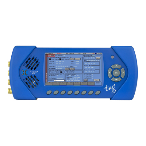
Phabrix SxTAG User manual

ii PHSXT-200 3Contents 11/14
Contents
About this Manual
Notice
The information in this document has been produced by PHABRIX Ltd with care and is believed
to be accurate. PHABRIX Ltd does not assume responsibility for loss or damage resulting from
errors, omissions or inaccuracies herein. This document is subject to change and revisions may
be made and issued to include such changes.
No part of this document may be reproduced, stored in a retrieval system or transmitted in any
form or by any means, electronic, mechanical, recorded or otherwise without the prior written
consent of PHABRIX Ltd.
Copyright © PHABRIX Ltd. All rights reserved. Software products licensed are owned by
PHABRIX Ltd and are protected by international treaty provisions and national copyright laws.
Revision
This manual is a revision controlled document. Any changes to any page content will be
reflected in the overall revision status of the whole manual.
Revision Date Software Version Comment
1 28/02/2014 0.12.0024 First release of manual
2 15/07/2014 1.01.12275 Full product release
3 12/11/2014 1.02.12980 Power management
Phabrix® Limited

SxTAG Operation Manual iiiPHSXT-200 3
Contents
Getting Started
Package Contents
The shipping box should contain the following:
1 black carrying bag containing:
PHABRIX SxTAG unit
Power Supply Unit
Mains lead
CD Manual
The shipping box will also contain this Manual on a CD, note that the Web Site always contains
the latest version of the manual. The version of software that this manual supports is on the
front page.
General Safety
Avoiding Personal Injury
This instrument is designed for use by qualified personnel only.
No user serviceable parts are provided. Units should be returned to your local
PHABRIX agent for servicing.
The Operator should NOT remove the case from the unit.
Do not spill any liquid onto the unit or its power adaptor.
Do not look directly into the fibre optic connections of cable as this may cause
permanent damage to the eye.
Power Supply
Make sure that the unit is connected to the correct power supply voltage. A power supply
adaptor is supplied with the unit which may be connected to any AC power supply between
100 and 240VAC at 50-60Hz. Only the supplied power adaptor should be used with the
unit. Do not use a damaged AC cable with the unit as it may cause a shock or fire hazard.
Replacement AC cables are available from your local PHABRIX agent.

iv PHSXT-200 3Contents 11/14
Contents
Installation Environment
Operating Temperature
The unit should only be operated between 0 and 40 °Centigrade. If the unit is
operated at a higher temperature there is a possibility of a fire hazard. If the
temperature is changed rapidly from a cold environment to a hot environment,
moisture can be created internally which can cause malfunction or damage the
unit. Allow the unit to sit for 30 minutes without power applied to reduce any
possibility of condensation. If the temperature rises above 60°Centigrade a
warning dialog will be given. If the temperature rises above 65°Centigrade the
unit will be turned OFF. Under both conditions, an event will be added to the
event log to show what happened.
Input/Output Terminals
Do not connect the input or output BNC connectors to external power as this can damage the
internal circuitry and cause the unit to work incorrectly.
The BNC connectors fitted on this unit are 75Ω type which are not compatible with 50Ω plugs.
The use of 50Ω plugs will permanently damage the connectors on the unit. The
use of 50Ω plugs is considered to be misuse of the equipment and will therefore
invalidate the unit’s warranty.
SFP Cage
When the SFP cage is fitted, either an SFP or a bung must be fitted in the SFP
cage at all times to prevent the SxTAG overheating.
When Not In Use
Disconnect the unit from the power supply and AC power source when not in use.
Maintenance
Wipe the case, and knobs gently with a soft cloth, lightly dampened with a neutral cleaning
agent. A screen cleaning cloth may be used to clean the LCD. Do not apply force to the LCD
when cleaning or it may be damaged.
Remove the power supply from the unit and turn OFF before cleaning. Do not
allow any water or other liquid to enter the unit while cleaning.

SxTAG Operation Manual vPHSXT-200 3
Contents
Disposal of Equipment
This product is subject to the European WEEE (Waste Electrical and
Electronic Equipment) directive and should be disposed of according to the
regulations of each country.

vi PHSXT-200 3Contents 11/14
Contents

SxTAG Operation Manual viiPHSXT-200 3
Contents
Contents
Contents
Getting Started iii
Package Contents........................................................................................................iii
General Safety.............................................................................................................iii
Avoiding Personal Injury.........................................................................................iii
Power Supply .........................................................................................................iii
Installation Environment .............................................................................................iv
Operating Temperature ..........................................................................................iv
Input/Output Terminals...........................................................................................iv
SFP Cage................................................................................................................iv
When Not In Use ....................................................................................................iv
Maintenance ..........................................................................................................iv
Disposal of Equipment ................................................................................................ v
Description
SxTAG Instrument 1–3
Overview..................................................................................................................... 1–3
Turning on and off the instrument ............................................................................... 1–3
Menu Operation ......................................................................................................... 1–4
Main Menu ............................................................................................................ 1–4
Instrument Status................................................................................................... 1–5
Using the Menus .................................................................................................... 1–5
Input / Output Selection ......................................................................................... 1–6
SxTAG Software Options ............................................................................................. 1–7
Overview ................................................................................................................ 1–7
SDI data stream analysis ....................................................................................... 1–7
Command scripts with print report ......................................................................... 1–8
Enhanced remote control........................................................................................ 1–8
2K-SDI Option ........................................................................................................ 1–10
Ancillary Data status.............................................................................................. 1–10
Dolby bit-stream Analyzer ...................................................................................... 1–10
Dolby bit-stream Generator.................................................................................... 1–11
AES Eye.................................................................................................................. 1–11

viii PHSXT-200 3Contents 11/14
Contents
Contents
Menu Reference
Generator Menu 2–3
Video Out (Generator Option) ..................................................................................... 2–3
Output ................................................................................................................... 2–3
Standard ................................................................................................................ 2–3
Colour Format ........................................................................................................ 2–4
EDH........................................................................................................................ 2–4
Errors ..................................................................................................................... 2–4
SMPTE 352............................................................................................................ 2–4
Pattern ................................................................................................................... 2–5
Ident ...................................................................................................................... 2–7
Sx 2K-SDI Option ................................................................................................... 2–8
Genlock Menu............................................................................................................. 2–9
Source.................................................................................................................... 2–9
Reference Out ........................................................................................................ 2–9
Delay ..................................................................................................................... 2–9
Audio Group Menu...................................................................................................... 2–10
Group n.................................................................................................................. 2–10
Master ................................................................................................................... 2–10
Analog o/p.............................................................................................................. 2–10
AES o/p .................................................................................................................. 2–10
Dolby (Dolby Generator Option).................................................................................. 2–11
Overview ................................................................................................................ 2–11
Dolby E .................................................................................................................. 2–11
Dolby Digital .......................................................................................................... 2–11
Dolby Digital Plus................................................................................................... 2–12
Dolby E Synchronisation - Generator Reference ..................................................... 2–12
Editing Program Information .................................................................................. 2–12
Program Meta Data Editing ................................................................................... 2–13
Default Program Meta Data................................................................................... 2–15
Embedding Dolby on SDI Stream............................................................................ 2–15
Embedding Dolby Signals on AES Stream............................................................... 2–15
Analyzer Menu 2–17
Overview..................................................................................................................... 2–17
Picture ........................................................................................................................ 2–18
Analyzer Source Selection ...................................................................................... 2–18
Sample, Line and Field Selection ............................................................................ 2–18
Aspect Ratio........................................................................................................... 2–18
Zoom ...................................................................................................................... 2–19
Active Picture ......................................................................................................... 2–19
Cursor .................................................................................................................... 2–19
Composite Input Termination .................................................................................. 2–19
Blue ....................................................................................................................... 2–19

SxTAG Operation Manual ixPHSXT-200 3
Contents
Waveform Monitor ...................................................................................................... 2–20
Analyzer Source Selection ...................................................................................... 2–20
Sample, Line and Field Selection ............................................................................ 2–20
Waveform Type ...................................................................................................... 2–21
Magnification ......................................................................................................... 2–21
Cursors................................................................................................................... 2–21
Setup Button Dialogue ........................................................................................... 2–22
External Reference ................................................................................................. 2–22
Vectorscope................................................................................................................. 2–23
Analyzer Source Selection ...................................................................................... 2–23
Sample, Line and Field Selection ............................................................................ 2–23
Magnification ......................................................................................................... 2–24
Graticule ................................................................................................................ 2–24
Setup Button Dialogue ........................................................................................... 2–24
Composite Subcarrier Phase Alignment.................................................................. 2–24
Signal Data ................................................................................................................. 2–25
Analyzer Source Selection ...................................................................................... 2–25
Type ....................................................................................................................... 2–25
Signal Information Menu 2–27
Overview..................................................................................................................... 2–27
Video Status................................................................................................................ 2–27
EDH/CRC ERRORS.................................................................................................. 2–27
EDH DATA .............................................................................................................. 2–27
Cable Length .......................................................................................................... 2–28
Active Picture CRC.................................................................................................. 2–28
MISC Status ................................................................................................................ 2–29
Payload ID – SMPTE 352 ...................................................................................... 2–29
Video Format ......................................................................................................... 2–29
Video Timing ............................................................................................................... 2–30
ANC Status (ANC Option) ........................................................................................... 2–31
ANC Inspector (SDI Data Option) ................................................................................ 2–32
ANC Inspector Setup .............................................................................................. 2–33
Error Triggers ......................................................................................................... 2–33
SFP Info ...................................................................................................................... 2–34
Audio Menu 2–35
Meters ........................................................................................................................ 2–35
Audio Status ............................................................................................................... 2–36
Dolby Status (Dolby Analyzer Option) ......................................................................... 2–37
Overview ................................................................................................................ 2–37
Dolby E .................................................................................................................. 2–37
Dolby Digital .......................................................................................................... 2–37
Dolby Digital Plus................................................................................................... 2–38
Analyser Reference ................................................................................................ 2–38
Source selection ..................................................................................................... 2–38
Dolby E Framing Values ......................................................................................... 2–38
Dolby E Programme configuration.......................................................................... 2–39
Dolby Digital Programme configuration ................................................................. 2–40
Dolby Digital Plus Programme configuration .......................................................... 2–40
Programme Metadata............................................................................................ 2–41
Peak Metering........................................................................................................ 2–42
AES Eye (CVBS In) Option ........................................................................................... 2–43

x PHSXT-200 3Contents 11/14
Contents
System Menu 2–45
Memories.................................................................................................................... 2–45
Saving Memories ................................................................................................... 2–45
Recalling Memories................................................................................................ 2–45
Renaming Memories .............................................................................................. 2–45
Adding Additional Memories .................................................................................. 2–46
Clearing Memories ................................................................................................. 2–46
Exporting Memories............................................................................................... 2–46
Disk Space ............................................................................................................. 2–46
Command Scripts........................................................................................................ 2–47
Steps, Actions and Parameters............................................................................... 2–47
Creating Command Scripts..................................................................................... 2–48
Editing Command Scripts ....................................................................................... 2–48
Running a Script..................................................................................................... 2–49
Network ...................................................................................................................... 2–50
Remote Control of Sx Instrument (Cost Option) ...................................................... 2–50
Misc............................................................................................................................ 2–51
Changing The Date/Time ........................................................................................ 2–51
Changing the Date Format: .................................................................................... 2–51
Setting LCD Brightness........................................................................................... 2–51
Setting Screen Saver Mode .................................................................................... 2–51
Setting User Language ........................................................................................... 2–51
Changing Options Security Code ............................................................................ 2–51
Utils ............................................................................................................................ 2–52
Dealer Features...................................................................................................... 2–52
Hardware Status .................................................................................................... 2–52
System Temperature............................................................................................... 2–52
Voltages ................................................................................................................. 2–52
Engineer...................................................................................................................... 2–53
Clear Memories...................................................................................................... 2–53
Default Settings...................................................................................................... 2–53
SDI In - SFP Out ..................................................................................................... 2–53
Set User Login........................................................................................................ 2–53
Adding/Deleting Users............................................................................................ 2–54
Editing The Prompt Text ......................................................................................... 2–54
Software Upgrade .................................................................................................. 2–55
CVBS Out Gain ....................................................................................................... 2–55
CVBS Inputs ........................................................................................................... 2–55
Audio Calibration ................................................................................................... 2–55
Logging Menu 2–57
Overview..................................................................................................................... 2–57
Event Log.................................................................................................................... 2–57
Log Setup.................................................................................................................... 2–58
Audio Thresholds.................................................................................................... 2–58
Video Status........................................................................................................... 2–58
AES Status ............................................................................................................. 2–59
Dolby Status (Requires Dolby Analysis Option) ...................................................... 2–59
Logging .................................................................................................................. 2–59
Log Time Limit........................................................................................................ 2–59
Log ANC Status........................................................................................................... 2–60
Speaker Menu 2–61
Overview..................................................................................................................... 2–61

SxTAG Operation Manual xiPHSXT-200 3
Contents
Glossary
Glossary of Terms A–3
Specification
SxTAG Instrument B–3
Operating Environment...............................................................................................B–3
Expected Behavior ......................................................................................................B–3
LCD Monitor...........................................................................................................B–3
LCD Flicker.............................................................................................................B–3
Remote Network Operation....................................................................................B–3
Dimensions .................................................................................................................B–3
Front Panel .................................................................................................................B–4
BNC Panel...................................................................................................................B–4
SDI I/O ...................................................................................................................B–4
PAL/NTSC Out ........................................................................................................B–5
PAL/NTSC (AES Eye) IN...........................................................................................B–5
REF I/O (.................................................................................................................B–5
SFP Cage (Option) ..................................................................................................B–5
Control Panel ..............................................................................................................B–6
Power Connection...................................................................................................B–6
Networking.............................................................................................................B–6
Audio I/O Connector ...............................................................................................B–6
Analogue Balanced Audio Input (15-Way Connector) .............................................B–6
Analogue Balanced Audio Output (15-Way Connector) ..........................................B–7
Analyzer AES Input (15-Way Connector).................................................................B–7
Generator AES Output (15-Way Connector)............................................................B–7
Headphone Output.................................................................................................B–7
Local Control..........................................................................................................B–7
Supported Video Formats B–9
SD 270 Mb/s ..............................................................................................................B–9
HD 1.485 Gb/s (SMPTE 292M) ..................................................................................B–9
Dual Link 1.485 Gb/s (SMPTE 327M).........................................................................B–10
3G Level-A 2.97 Gb/s (SMPTE 425M-A) .....................................................................B–12
3G Level-B 2.97 Gb/s (SMPTE 425-B).........................................................................B–13
2K-SDI Formats Option...............................................................................................B–14

xii PHSXT-200 3Contents 11/14
Contents
Maintenance
Warranty C–3
Overview.....................................................................................................................C–3
Warranty Exceptions ...................................................................................................C–3
Product Registration ...................................................................................................C–3
Maintenance C–5
General Maintenance ..................................................................................................C–5
Preventative Maintenance...........................................................................................C–5
Software Maintenance C–7
Installing New Software...............................................................................................C–7
Software Download from Internet...........................................................................C–7
FTP Transfer from a connected PC..........................................................................C–8
Reverting to a Earlier Version of Software ...................................................................C–8
Sx File Structure .........................................................................................................C–9
Patterns .................................................................................................................C–9
Scripts....................................................................................................................C–9
Setup .....................................................................................................................C–9
Idents.....................................................................................................................C–9
Fonts ......................................................................................................................C–10

SxTAG Operaon Manual 1–1PHSXT-200 3
1Description
PHABRIX
®
®
broadcast excellence

1–2 PHSXT-200 3Descripon 11/14
Description

SxTAG Operaon Manual 1–3PHSXT-200 3
Description
SxTAG Instrument
Overview
Configured as an entry level portable analyser, the TAG can be easily upgraded using a range of
software options to provide a sophisticated instrument for testing broadcast infrastructures.
The PHABRIX® TAG has been created to incorporate new interfaces that appeal to customers
looking for a cost effective entry into professional test and measurement.
The PHABRIX® TAG includes support for SD-SDI and HD-SDI as standard with the option to
upgrade to 3G-SDI (Level A and Level B).
Composite analysis and generation has been incorporated to support those regions making the
transition between analogue and digital television.
An SFP cage has been integrated into the design principally for optical infrastructure testing,
however, the cage will support a wider range of SFPs as they become available. Composite
locking reference generation and input reference waveform analysis have also been included.
For audio support the PHABRIX® TAG provides a D15 breakout connector providing both
balanced analogue and AES input/output. AES waveform display allows a visual check of levels
and reference lock. Advanced audio features including Dolby® E, Dolby® Digital and Dolby®
Digital Plus are supported allowing TAG to be considered as a replacement for the discontinued
Dolby® DM100.
Internal Speaker Menu Buttons Cursor/OK Buttons
Power On/Off
Turning on and off the instrument
To turn on your PHABRIX SxTAG Instrument press the red button at the top right hand corner
of the front panel.
Once the system has started, pressing the button again will turn it off. If for some reason the
instrument stops responding, pressing and holding the button for a few seconds will turn it off.
The unit is battery operated and the battery should last for between 3 and 6 hours dependent
on which video standard is being used and whether the input and outputs are active. If the
unit is turned ON and the battery is almost discharged, it will turn itself OFF. If the battery
level starts to get too low for operation a dialogue will be displayed prompting the user to turn
off the unit. The current settings will also be saved. The unit should then be connected to the
power supply unit as soon as possible to recharge the battery. The battery should be fully
charged in about 4 hours. The battery will charge faster if the unit is turned off while charging.

1–4 PHSXT-200 3Descripon 11/14
Description
Menu Operation
Main Menu
The Main menu, displayed on the OLED screen gives access to the software modules available
on the SxTAG instrument. The buttons beneath the screen correspond to the menu areas.
Pressing on any of these buttons will display the corresponding menu.
This page displays an overview for the system. It shows the video input and output standards
and frame rate. The audio status for the generator shows which audio groups are being
generated whilst the audio status for the input shows which groups are present and an overview
of the channel status for each audio channel.
Audio channel status is displayed as:
‘P’ if PCM audio is present,
‘N’ if NON-PCM audio is present,
‘E’ if Dolby-E packets are present
‘D’ if Dolby-Digital packets are present
‘+’ if Dolby-Plus packets are present
V if the validity bit is set
Dolby-E program configuration and Timing status is also displayed if the Dolby-E analysis
option has been purchased and a Dolby-E signal has been detected on the selected input.
If the generator is generating errors then the video standard is displayed in red. If the input
detects errors, then the input standard will be displayed in red if the analyser is monitoring the
input.
If the unit is connected to the network, the current TCP/IP address of the unit is displayed in
the Remote Control box. If the unit is NOT connected to a network and is set to DHCP mode,
it will show ‘acquiring’ to show that the connection hasn’t been made yet. The model type is
displayed at the bottom right corner of the screen.

SxTAG Operaon Manual 1–5PHSXT-200 3
Description
Instrument Status
The top line of the menus shows the unit status and includes the Input Video status, Genlock
status, battery status and current time. If the unit is being powered by the AC adaptor, the
battery status will not be shown. If a command script is being run, this is shown on the top line
to the left of the time as “Script”. A red “Log” is shown on the status line if there are any events
in the event log.
A red “Log” is shown on the status line if there are any events in the event log.
If a 3G video standard is selected the video standard display will be shown as 3GA if it is a
3G-Level A standard, 3GB if it is a 3G-Level B dual link standard, 3G2 if it is a 3G-level B dual
stream (two patterns) standard or DL if it is a dual link output.
The input video standard will be shown in red if the input signal has errors, but only if the
analyzer is connected to the input. If the analyzer is set to monitor the output, the input
standard will be shown in brown.
The output standard will be shown in red if the instrument is generating errors. The output
standard will show OFF if the generator output is Off.
Using the Menus
The Main menu is the top level menu from which all other menus are selected on the SxTAG
instrument. The main menus are:
Generator allowing the unit to be locked to an external reference and providing a
fully populated Composite, SD-SDI, HD-SDI and Fibre video test pattern
generator and audio tone generator if the Generator option is installed.
Analyser allows the selected Composite, SDI or Fibre input signal to be analysed in
the form of a Picture, Waveform monitor and Vectorscope.
Sig Info allows detailed signal information about the video and audio status for the
SDI or Fibre video input source to be displayed.
Audio gives access to the Audio Meters and Audio Status displays allowing the
levels of the embedded SDI audio, AES audio and analogue audio to be
displayed.
System allows the setup of system wide settings including memories, date/time and
software.
Logging selects the logging page to view and setup the error logging system.
Speaker selects the speaker/headphone setup page to allow the selected embedded
SDI audio, AES audio and analogue audio to be heard.
See chapter 2 : “Menu Reference” for full details of these menus.
The Menu buttons select which instrument is in use as well as selecting the options for the
instrument. The bottom of the display shows the function of each Menu button.
When in a specific function eg Generator, Analyser etc, the cursor controls () on the
right hand of the instrument select a field to edit. The current field has a red box around it.
Pressing the OK button starts or ends editing of that field. Check boxes are always in edit mode
and pressing the OK button inverts the current state.
When editing some types of fields, the menu buttons at the bottom take on different
functionality to allow cancelling edit mode or setting the value for the field. When lists of
options are displayed the menu buttons allow selection of the first/last item in the list as well
as paging through the available options. If the list of items is small, the available items may be
displayed on the menu buttons for instant access.

1–6 PHSXT-200 3Descripon 11/14
Description
The buttons along the bottom of the display change the currently displayed page when
not editing a data field. The left hand button always selects the top level menu and system
overview page. So for example pressing the first button will select the “Main Menu”, selecting
the second button will select the “Generator” menu, selecting the third button with select
“Analyser”, etc.
Input / Output Selection
The SxTAG has 2 bidirectional BNC connections, one for Reference input / output and the other
for SDI video input / output.
The direction of SDI I/O connection is selected on the Main Menu using the drop down lists
as well as in the “Output” section of the “Generator” - “Video Out” menu. Note that if the
Generator software option is not installed then this connection will be an input.
The direction of the “Ref I/O” connection is selected on the Main Menu using the drop down list
or in the “Reference Out” section of the “Generator” - “Genlock” menu where it is controlled by
the “On” check box.
The input to be monitored using the Analyser can be selected in the drop down list in the
bottom right corner of the Picture, Waveform, Vectorscope, Signal Data and other Instruments.
If an SFP module is fitted the SPF Input can also be selected from this drop down list to be
monitored using the Analyser.
Both AES and Analogue audio output can be enabled using the drop down menus on the Main
Menu.

SxTAG Operaon Manual 1–7PHSXT-200 3
Description
SxTAG Software Options
Overview
The SxTAG instrument has a range of software options that can enhance its functionality for
specific applications.
The Generator option (PHSXT-GEN) allows
the creation of video test signals for
analogue composite video, SD-SDI and HD-
SDI video as standard. 3G-SDI, 2K SDI and
Fibre video functionality can be purchased
as additional options. The Generator option
also allows the generation of both analogue
and digital audio test tones and allows the
unit to be locked to an external locking
reference.
SDI data stream analysis
The SDI analysis option (PHSXOSD)
provides the engineer with a detailed view
of the data words contained within the
SDI stream. This allows the analysis of
complex faults and is particularly useful
when determining compatibility issues
between equipment and when debugging
new product developments particularly in a
R&D environment. Detail within the active
SDI stream can be viewed with continuous
update.
The SDI Analysis option provides the following functional areas:
Grid displays the SDI data in the form of an array.
Stream allows the SDI continuous data stream to be viewed.
Component allows the video components to be displayed in separate columns.
Splt allows the video components to be display individually.
Ancillary Data allows the user to capture whole Ancillary data packets identified by their
data id (DID).
Ancillary Status allows additional ‘user defined’ selections with the appropriate DID or SDID
code.
Access to the SDI analysis functionality is via the Analyser - Signal Data menu. See the
“Analyser - Signal Data” section in chapter 2 for full details.

1–8 PHSXT-200 3Descripon 11/14
Description
Command scripts with print report
The Command Script option (PHSXOS)
allows a series of predefined actions to be
run through within the PHABRIX Sx using a
script stored in internal memory.
The command scripts option can be used
to automatically step through a sequence
of instrument states, controlling the
generator, analyser and logging functions.
If required the instrument will prompt the
user before going onto a subsequent state.
Applications include repeated test sequences as required by manufacturer Test Departments,
R&D Departments, Systems Integrators and Commissioning/Support Engineers.
A script requires a set of memories to configure the unit and then a script file which recalls
those memories and specifies times and actions for each step. The process of creating a
command script requires these two files to activate the sequence.
Additionally a script can be created as a simple text file on a PC and then transferred to the
unit via Ethernet and recalled at any time. A large number of named scripts and memories may
coexist within the instruments store to be recalled as required.
Access to the Command Scripts functionality is the “System” - “Command Scripts” menu. See
chapter 2 for details.
Enhanced remote control
The Enhanced remote control option
(PHSXOR) gives users full remote control
of the unit via TCP/IP Sockets to allow
any aspect of the unit to be modified or
queried.
This allows complex applications to be
created to perform test and measurement
functions such as automated testing of
routers or other broadcast equipment.
PHABRIX products act as a server and listen on a port waiting for incoming requests from
clients such as a PC. Using this method of communication the Sx range can provide a variety
of information to the control device it is connected to and be controlled in specified areas of
the product using the command details included. All visual controls on the product have an
associated command.
Messages may be sent to ‘set’ or ‘get’ data from a command ie if you ‘set’ a value the unit
will be configured accordingly and a reply returned and if you ‘get’ a value from the PHABRIX
unit it will reply with that value. All messages are acknowledged to increase the security of the
interface ie closed loop communication.
The control structure can be selected as Passive or Active. Passive control allows simple remote
control where the host PC is in control and sends commands when it wants to change data or
get information. It is this method which is the most popular use for remote control.
Other manuals for SxTAG
1
This manual suits for next models
1
Table of contents
Other Phabrix Test Equipment manuals