Fieldpiece MR45CAN User manual

Fieldpiece®
Refrigerant
Recovery Machine
OPERATOR'S MANUAL
Model MR45CAN

32
Contents
Important Notice . . . . . . 4
What’s Included. . . . . . . 4
Warnings . . . . . . . . . 4
Specifications . . . . . . . 5
Description . . . . . . . . 6
Features
Certifications . . . . . . . 8
UL Veried Performance Data
Safety Information. . . . . . 9
First Aid for Refrigerant Exposure
General
Environmental
Personal Protection
MR45CAN Protection
Setup
Operational
Grounding Instructions
Tech Tips . . . . . . . . .12
General
Setup
Operational
Controls . . . . . . . . . 14
Display and Buttons
Status Icons and Messages
Port Routing Control
MR45CAN Refrigerant Flow
Dynamic Pressure Measurement
Functions . . . . . . . . . 22
Self Test
Self Purge
Purging a Recovery Cylinder
Direct Liquid/Vapor Recovery
Push/Pull Recovery
Troubleshooting . . . . . . 28
Status Messages
Other Symptoms
Maintenance. . . . . . . . 30
General
Mesh Screen Filter
Limited Warranty . . . . . . 32
Obtaining Service

54
Important Notice
This is not a consumer machine. Only qualied
personnel trained in the recovery or pumping of
refrigerant may operate this machine.
Read and understand this operator’s manual
in its entirety before using MR45CAN to prevent
injury or damage to you or equipment.
What’s Included
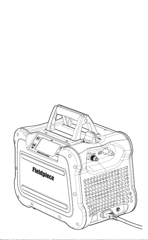
MR45CAN Refrigerant Recovery Machine
10 Extra Mesh Screens for Input Port
3 Extra O-ring for Input Port
Operator’s Manual
1 Year Warranty
Specifications
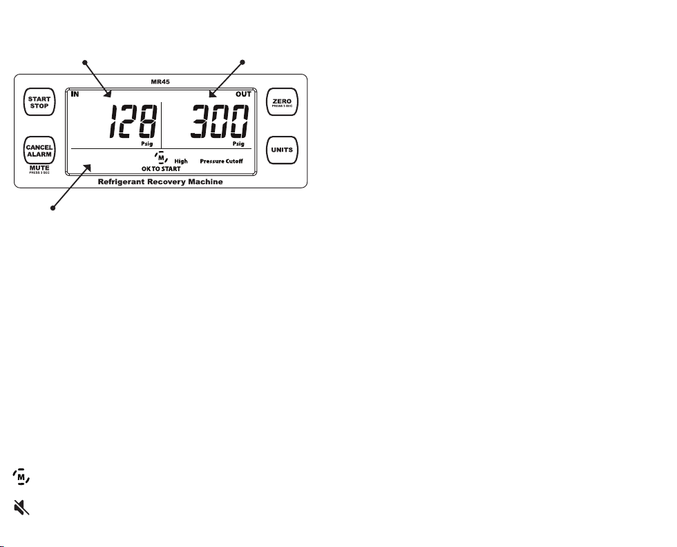
Display: 2 x 10000 count LCD with status messages
Backlight: Blue color
Measurement rate: 3.3 times per second, nominal
Input Port Pressure Sensor Range:
-30”Hg to 600 psig (-76 cmHg to 4100 kPa)
Output Port Pressure Sensor Range:
-30”Hg to 600 psig (-76 cmHg to 4100 kPa)
High Pressure Cutoff: 558 psig (3850 kPa), nominal
Resolution and Units: 1 psig (1”Hg), 0.05 bar (2 cmHg),
0.01 Mpa (2 cmHg), 5 Kpa (2 cmHg)
Pressure Sensor Accuracy:
± 0.5“ Hg, ± 1.3 cmHg (Vacuum)
± (0.6% of reading +2 psig), ± (0.6% of reading +14 kPa)
Final Recovery Vacuum: 14.9”Hg, 38 cmHg
Compressor: Twin cylinder reciprocating (oil-less)
DC Motor: 1 HP (variable smart speed)
Power Source: 120 VAC @ 60 Hz 1 phase
Nominal Current Draw: 12.0 AAC
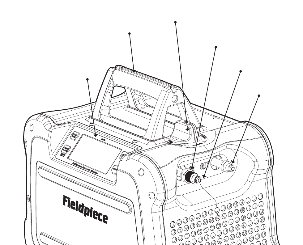
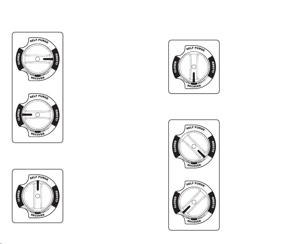
Valve: Single dual-route ball valve
Input Port Filtration: 9 mm mesh screen, stainless
Dimensions: 14.8 inch x 9.8 inch x 13.5 inch
376 mm x 250 mm x 344 mm
Weight: 22 lbs, (10kg)
Operating Environment: 32°F to 104°F (0°C to 40°C)
Storage Environment: -4°F to 140°F (-20°C to 60°C)
Approved Refrigerants: R12, R134A, R22, R401A (MP39), R401B,
R401C, R402A, R402B, R404A, R406A, R407A, R407B, R407C,
R407D, R408A, R409A, R410A, R411A, R411B, R412A, R500, R502,
R507, R509.
US Patent: www.fieldpiece.com/patents
!
WARNINGS
Ensure proper equipment grounding, electrical shock risk.
Do not expose to rain, electrical shock risk. Store indoors.
Do not use to pump hydrocarbons, explosion risk.
Do not use to pump flammable media, explosion risk.
Inhalation of high concentrations of refrigerant vapor can
block oxygen to the brain causing injury or death.
Refrigerant liquid can cause frostbite.

76
Features
• Lightweight (22 lbs)
• Smooth and Fast Operation (1 HP DC Motor)
• Digital Display with Status Messages
• Reliable Rubberized Construction
• Easy to Access Port Design
• Hex Nut Secures Input Port During Hose Removal
• Power Cord Storage
• Ceramic Cylinders
• Self Purge
• Operation Down to 95VAC
• UL Verified to Section 608 of EPA Clean Air Act
• UL Verified to AHRI Standard 740
Description
The MR45CAN is the rst variable speed DC
motor recovery machine with a digital display.
Pump refrigerant easier and quieter than ever
before. Connect your hoses without navigating
around dark tight spaces or picking the pump o
the ground. View status messages and pressures
directly on the big bright display.
Carry the machine to and from the job site
easily and well protected from environmental
hazards.Turn the single rubberized control valve
to route refrigerant through MR45CAN, and use
the self-purge function to pump the last traces
into the recovery cylinder instead of being left in
the machine or released into the environment.

98
Certifications
WEEE (Do not dispose through
typical waste streams.)
IN ACCORDANCEWITH SECTION 608 OF THE CLEAN AIR ACT:
THIS EQUIPMENT HAS BEEN CERTIFIED BY UNDERWRITERS
LABORATORIES INC. TO MEET EPA’S MINIMUM REQUIREMENTS FOR
RECOVERY EQUIPMENT INTENDED FOR USE WITH CATEGORY III,
IV, AND V REFRIGERANTS OUTLINED IN AHRI 740-2016,TABLE 4.
<SA44565>
UL Verified Performance Data
Refrigerant R22 R134A R407C R410A
Liquid Recovery
(kg/min) 4.7 2.9 5.1 5.6
Vapor Recovery
(kg/min) 0.28 0.28 0.33 0.33
Final Recovery Vacuum
(kPa) 50.8 50.8 50.8 50.8
Residual Trapped
Refrigerant (kg) 0.005 0.008 0.004 0.005
High Temp (104°F) Vapor
Recovery (kg/min) 0.40 - - -
Safety Information
First Aid for Refrigerant Exposure
Inhaled: Move to fresh air immediately.
Eye: Immediately flush eye with water. Seek medical attention.
Skin: Immediately flush skin with water. Seek medical attention.
General
1. This is not a consumer machine. Only qualified personnel trained
in the recovery or pumping of refrigerant may operate this
machine.
2. Read and understand this operator’s manual in its entirety
before using MR45CAN to prevent injury or damage to you or
equipment.
Environmental
1. Use only within operating environment specification.
2. Ensure fan opening is clear of debris.
3. Explosion and fire risks:
Do not use near sewer lines.
Do not use in poorly ventilated enclosed areas.
Do not use near gasoline, acetylene, or other flammable gases.
Do not use to pump hydrocarbons.
Do not use near flames or sparks.
Assume all components are pressurized.
Personal Protection
1. Frostbite danger. Be careful using hoses.
2. Use personal protective equipment:
Wear safety goggles.
Wear earplugs if using for long durations.
Wear protective gloves.

1110
MR45CAN Protection
1. Use only on approved list of refrigerants (page 8).
2. Do not use with hydrocarbons.
3. Ensure mesh screen filter is installed and clean (page 30).
Setup
1. Repair any damaged parts before using.
2. Disconnect power and allow fan to stop before opening or
servicing MR45CAN.
3. Perform self test periodically (page 22).
4. Ensure power cord is not damaged.
5. Ensure all equipment is grounded.
6. Extension cord options:
14 AWG or thicker, up to 50 feet (15 m)
DO NOT USE 18 AWG!
NOTICE: Risk of Property Damage. The use of an undersized
extension cord will cause voltage to drop resulting in power loss
to the motor and overheating.
7. Ensure extension cord is grounded, 3 conductor, and is not
damaged.
Operational
1. Use correct refrigerant hoses with ball valve shutoffs.
2. Keep track of the current amount of refrigerant in the cylinder.
Refrigerant scales are a good way to do this.
3. Overfilling a cylinder past 80% can cause an explosion and
violates DOT laws.
4. Close cylinder off from refrigerant if it reaches 80% of its capacity.
5. Use only DOT CFR 49 or UL-approved refrigerant cylinders for the
refrigerant being recovered.
6. Use recommended accessories.
7. Use a small filter drier on the input port and change it often to
protect machine from contaminated refrigerants.
8. Monitor pressures and temperatures.
9. Self purge MR45CAN after each use. No refrigerant should remain
in the machine.
Grounding Instructions
This product must be grounded. In the event of an electrical short
circuit, grounding reduces the risk of electric shock by providing an
escape wire for the electric current. This product is equipped with a
cord having a grounding wire with an appropriate grounding plug.
The plug must be plugged into an outlet that is properly installed and
grounded in accordance with all local codes and ordinances.
WARNING – Improper installation of the grounding plug is able to
result in a risk of electric shock. When repair or replacement of the cord
or plug is required, do not connect the grounding wire to either flat
blade terminal.The wire with insulation having an outer surface that is
green with or without yellow stripes is the grounding wire.
Check with a qualified electrician or serviceman when the
grounding instructions are not completely understood, or when in
doubt as to whether the product is properly grounded. Do not modify
the plug provided; if it does not fit the outlet, have the proper outlet
installed by a qualified electrician.

1312
Tech Tips
General
1. Store in the self purge or recover position. Do not store in the
CLOSED position as trapped air and refrigerant can expand and
damage components.
2. For extended storage, purge with nitrogen, set to RECOVER, and
screw non-sealing caps onto the ports.
3. Recovery machines are not vacuum pumps and should not be
used for deep evacuations.
4. Do not run the machine without the mesh screen filter (page 30).
Doing so will void the warranty and damage the machine.
5. Understand the refrigerant safety data sheet (SDS).
Setup
1. Know the refrigerant of the system and make sure your recovery
cylinder matches that type.
2. Hoses:
Short as possible (3/8”hose with 1/4”fitting).
Core depressors removed.
Ball valve shutoffs instead of low loss fittings.
Replace if worn.
3. Manifold gauges are not necessary for recovery but can make it
more convenient and increase speed by having 2 system hook
ups.
4. Use a Schrader valve core removal tool to temporarily remove
valve cores from service valves.
5. Use the push-pull method if recovering over 30 lbs (14kg).
6. Evacuate your empty recovery cylinders to 29.6”Hg (75 cmHg)
before use.
7. Know how much refrigerant you expect to recover before
starting.
8. Ensure there’s enough room in the recovery cylinder to not
exceed 80% filled during the job, or monitor and have a second
cylinder ready.
9. Always purge hoses before recovery. If cylinder is too hot, use an
ice bath to reduce the temperature and pressure of the cylinder.
10. If cylinder pressure is higher than expected, you can purge non-
condensables into another cylinder (page 23).
Operational
1. Recover as much liquid as possible before recovering vapor.
2. Recovery is faster when the recovery cylinder is cooler.
3. You can use a heat gun to warm refrigerant lines to boil trapped
refrigerant.
4. Recover from both suction and liquid lines at the same time for
faster vapor recovery.

Port Routing Control Knob
Input Port
Mesh Screen Filter
Backlit Digital Dual Display and Buttons
Output Port
Power Cord Storage
1514
Controls

1716
Display and Buttons
Input Pressure Output Pressure
Status Icons and Messages
START/STOP
Start or Stop the motor.
ZERO (press 3 seconds)
Zero pressure sensors. Ports must be open to atmosphere.
CANCEL ALARM
Cancel alarm currently sounding (temporarily mute).
MUTE (press 3 seconds)
Toggle mute for all sounds (setting is saved).
UNITS
Select pressure/vacuum units.
Status Icons and Messages
The icon rotates when the motor is running.
The icon is shown when MR45CAN is set to MUTE.
OK TO START
Motor stopped. Temperatures, voltages, and pressures are currently
safe to start the motor again.
COMPLETE
Motor stopped. Purge or recovery has reached 10”Hg or 20”Hg
(25 cmHg or 50 cmHg) vacuum for 10 sec.
Input Closed
Cannot zero pressures. Open input port.
Output Closed
Cannot zero pressures. Open output port.
High Voltage Warning
Motor stopped. Voltage was above 130 VAC.
Low Voltage Warning
Motor stopped. Voltage was below 95VAC.
High Pressure Cutoff
Motor stopped. Output (cylinder) approached dangerous pressure.
Low Pressure Cutoff
Motor stopped. Input reached 10”Hg or 20”Hg (25 cmHg or 50
cmHg) vacuum for 10 sec.
Motor Fault 1
Motor stopped. Motor temp. measured above operating range.
Motor Fault 2 (“throttle” shows on display)
Motor stopped. Motor current (amps) rose above operating range.
Throttle RECOVERY to reduce cylinder pressure (page 19).
Motor Fault 3
Motor stopped for unknown reason.

1918
Port Routing Control
OR
OR
CLOSED
• Input and Output closed.
• Set to either closed position to close
off both ports during setup.
OR
OR
SELF PURGE
• Input closed, Output open.
• After recovery is complete, set to
this position to close the IN port
before you START the purge.
OR
OR
RECOVER
• Input and Output fully open.
• Set to this fully open position for
most of the recovery process.
OR
OR
RECOVER (throttled)
• Input and Output partially open.
• Rotate away from RECOVER in
either direction to reduce liquid
slugging if knocking occurs.This
slows the flow of refrigerant
so the machine operates more
smoothly.
• Only throttle as much as needed for
smooth operation.

2120
MR45CAN Refrigerant Flow
Refrigerant liquid and vapor are pulled through
the machine by the pressure dierence created
by the compressor. For maximum performance,
increase the IN pressure and reduce the OUT
pressure. See Tech Tips (page 12).
Compressor
Input
Pressure
Sensor
Output
Pressure
Sensor
OUT
Port
IN
Port
Recovery
Cylinder
(typically)
System
(typically)
Manifold
(knob control)
Condenser
(microchannel)
Dynamic Pressure Measurement
MR45CAN pressure readings are designed only
for monitoring pressures. Do not use MR45CAN
for diagnostic pressure measurements.
If a system’s pressure is stable, MR45CAN
pressure readings will be close to your other
pressure gauges.
If a system’s pressure is changing, pressure
measurements at dierent locations within that
system will be dierent. For every 3 feet of 1/4”
hose, the pressure may have a difference of
approximately ± 20 psig (± 150 kPa).

2322
Functions
Self Test
Perform this test to ensure the high pressure
cuto and pump are operational.
1. Set knob to RECOVERY.
2. Open IN port to air.
3. Connect a ball valve to OUT port. (Included caps are not sealed.)
4. Close the ball valve.
5. Press START to create a pressure at the OUT port.
6. MR45CAN is working well if High Pressure Cutoff occurs around 550
psig (3800 kPa) within 45 seconds. Cutoff time can increase if a hose
is placed in front of your ball valve.
Self Purge
Use the SELF PURGE feature at the end of every
recovery to pump the last bit of refrigerant out
of MR45CAN. Benets include increased machine
life, reduced environmental impact, and most
importantly to prevent refrigerant mixing.
1. After recovery is complete, set knob to SELF PURGE. This closes the
IN port and routes the MR45CAN condenser to the intake of the
MR45CAN compressor.
2. Press START to empty MR45CAN into the recovery cylinder.
3. Once 10”Hg (25 cmHg) is reached for 10 seconds, the motor stops
automatically.
Purging a Recovery Cylinder
When the cylinder pressure is higher than
expected you may have non-condensables at the
top of the cylinder. Use a second deeply evacuated
cylinder to pull out the non-condensables.
1. Leave pressurized cylinder undisturbed overnight.
2. Use a vacuum pump to evacuate another cylinder.
3. Use your manifold gauges to connect the closed vapor ports of the
two cylinders.
4. Measure the vapor temperature of the pressurized refrigerant
cylinder.
5. Use a P/T chart or digital manifold to find specified pressure.
6. Open the evacuated vapor port.
7. Open (purge) the pressurized vapor port until pressure is reduced to
5 psi above specified pressure.
8. Close valves.
9. If desired, repeat in 15 minutes to allow the tank to settle again.

LV
Vapor
Schrader Valve Core
Removal Tools (optional)
Filter Drier
Manifold
Cylinder
Liquid
2524
Direct Liquid/Vapor Recovery
This is the typical recovery method. Vapor and
liquid lines are routed through your manifold,
into MR45CAN, and out to the recovery cylinder.
1. Close valves of recovery cylinder, MR45CAN, and manifold.
2. Set up as shown in the diagram.
3. Open valves of hoses and removal tools.
4. Set MR45CAN to RECOVER.
5. Open high side of manifold for liquid recovery.
6. To purge air from hoses, briefly unseat hose fitting at cylinder until
vapor is seen. Unseat hose fitting at low side of manifold to purge
low side hose.
7. Fully open vapor valve of recovery cylinder.
8. Press START to begin recovery.
9. Adjust the knob as needed to throttle refrigerant flow if liquid
slugging (knocking) occurs.
10. When liquid recovery is complete, open low side of manifold for
vapor recovery.
11. MR45CAN stops automatically after vacuum reaches 10”Hg (25
cmHg) for 10 seconds. For a deeper vacuum, press START to
continue recovery. MR45CAN stops again after vacuum reaches
20”Hg (50 cmHg) for 10 seconds. Press STOP to manually halt
recovery at any time.
12. Set knob to SELF PURGE and press START to empty MR45CAN.
MR45CAN stops automatically after vacuum reaches 10”Hg (25
cmHg) for 10 seconds.
13. Close manifold and cylinder valves after self purge is complete.
14. Remove hoses from MR45CAN, set knob to RECOVER, and cap ports.

LV
Vapor
Liquid
Filter Drier
Cylinder
Schrader Valve Core
Removal Tools (optional)
Sight Glass (optional)
2726
Push/Pull Recovery
This method is only for larger systems with at
least 30 lbs (14 kg) of liquid refrigerant. It’s used
to recover liquid before recovering vapor.
1. Close valves of recovery cylinder and MR45CAN.
2. Set up as shown in the diagram.
3. Open valves of liquid hose and removal tool at liquid system port.
4. To purge air from system liquid hose, briefly unseat hose fitting at
cylinder’s liquid port until vapor is seen.
5. Fully open liquid valve of recovery cylinder and allow to pressurize.
6. Set MR45CAN to RECOVER.
7. Press START to begin recovery.
8. Fully open vapor valve of recovery cylinder.
9. To purge air from hoses briefly unseat hose fitting at vapor system
port until vapor is seen.
10. Open valves of vapor hose and removal tool at vapor system port.
11. When liquid recovery is complete, press STOP to stop motor.
12. Close all valves and proceed to Direct Vapor Recovery (page 25).

2928
Troubleshooting
Status Messages
Input Closed
Cannot zero the displayed pressure because pressure sensor not
open to atmosphere. Open input port.
Output Closed
Cannot zero the displayed pressure because pressure sensor not
open to atmosphere. Open output port.
High Voltage Warning
Voltage was above 130VAC. Motor stopped. Ensure power network
voltage is between 95 and 130VAC @ 60 Hz.
Low Voltage Warning
Voltage was below 95 VAC. Motor stopped. Check power network to
ensure voltage is between 95 and 130 VAC @ 60 Hz.
High Pressure Cutoff
Output (cylinder) reached dangerous pressure. Motor stopped.
Ensure all valves after the output port are open.The cylinder may need
to be cooled or replaced to reduce pressure.
Low Pressure Cutoff
Input reached final recovery vacuum. Motor stopped. It’s normal
to see this after RECOVERY or SELF PURGE is complete. If unexpected,
ensure valves before the input port are open and the knob is not set to
CLOSED.
Motor Fault 1
Motor temperature measured above operating range. Motor
stopped. Extremely high ambient temperature, extended liquid
recovery time, or high cylinder pressure can be the cause. Allow
time for the motor to cool down before resuming, and throttle the
RECOVERY (page 19).
Motor Fault 2
Motor current (amps) rose above operating range. Motor stopped.
Extremely high ambient temperature, harsh liquid slugging, extended
recovery time, or high cylinder pressure can be the cause.Throttle
RECOVERY and start the motor. If fault occurs again, throttle even more
and start the motor (page 19).
Motor Fault 3
Motor stopped for unknown reason. If this occurs repeatedly, there
may be something wrong with MR45CAN.
Other Symptoms
MR45CAN never reaches 10”Hg or 20”Hg
vacuum.
Check for a leakage before the input port.
For 10”Hg vacuum, the recovery cylinder should be below 475psig.
For 20”Hg vacuum, the recovery cylinder should be below 230psig.
Input port shows frost or signs of leakage.
Ensure the grooved input fitting is hand tight before tightening the
hex nut (page 30).
Recovery is slower than normal.
There could be an input blockage. Check mesh screen filter for
blockage. Ensure knob is set to RECOVER.
Display does not turn on when plugged in.
Ensure power cord and outlet are okay.
Excessive noise during liquid recovery.
MR45CAN is experiencing a high load. Rotate the knob of MR45CAN
to throttle the refrigerant flow.

1.
2.
3.
4.
5.
Done
O-ring
Screen
Securing Hex Nut
Grooved Input Fitting
3130
Maintenance
General
Wipe with damp cloth to clean the exterior.
Do not use solvents.
To extend the life of internal seals, occasionally
pump a teaspoon of mineral oil through
MR45CAN.
Mesh Screen Filter
When the mesh screen lter becomes dirty
and clogged, it means it’s working to keep your
MR45CAN working well for a long time. You
need to clean or replace this screen often. Visit
our website for information on obtaining extra
mesh screens.
1. Loosen (counter clockwise) the securing hex nut on the IN port.
2. Unscrew (counter clockwise) the grooved input fitting.
3. Clean or replace the mesh screen.
4. Hand tighten (clockwise) the grooved input fitting.
5. Tighten (clockwise) the securing hex nut with 1/8 turn with a
wrench.

3332
Limited Warranty
This machine is warranted against defects in material or
workmanship for one year from date of purchase from an authorized
Fieldpiece dealer. Fieldpiece will replace or repair the defective unit, at
its option, subject to verification of the defect.
This warranty does not apply to defects resulting from abuse,
neglect, accident, unauthorized repair, alteration, or unreasonable use
of the machine.
Any implied warranties arising from the sale of a Fieldpiece product,
including but not limited to implied warranties of merchantability and
fitness for a particular purpose, are limited to the above. Fieldpiece
shall not be liable for loss of use of the machine or other incidental or
consequential damages, expenses, or economic loss, or for any claim of
such damage, expenses, or economic loss.
State laws vary. The above limitations or exclusions may not apply
to you.
Obtaining Service
Visit www.fieldpiece.com/rma for the latest information on how
to obtain service. Warranty for products purchased outside of the U.S.
should be handled through local distributors. Visit our website to find
your local distributor.

MR45CAN
© Fieldpiece Instruments, Inc 2022; v29
Other manuals for MR45CAN
1
Table of contents
Other Fieldpiece Test Equipment manuals