Checklist for 2110 Testing
Before starting to test in a 2110 environment, make sure that you have access to the following:
lNetwork domain providing an ST 2059 compatible Grandmaster PTPtiming signal.
lOptionally an NMOS-compatible, configuration, monitoring and control utility for in-band,
remote control of the IPSFP, for example, Riedel MNSET (available from the PHABRIXSupport
website under PHABRIXProduct Utilities.)
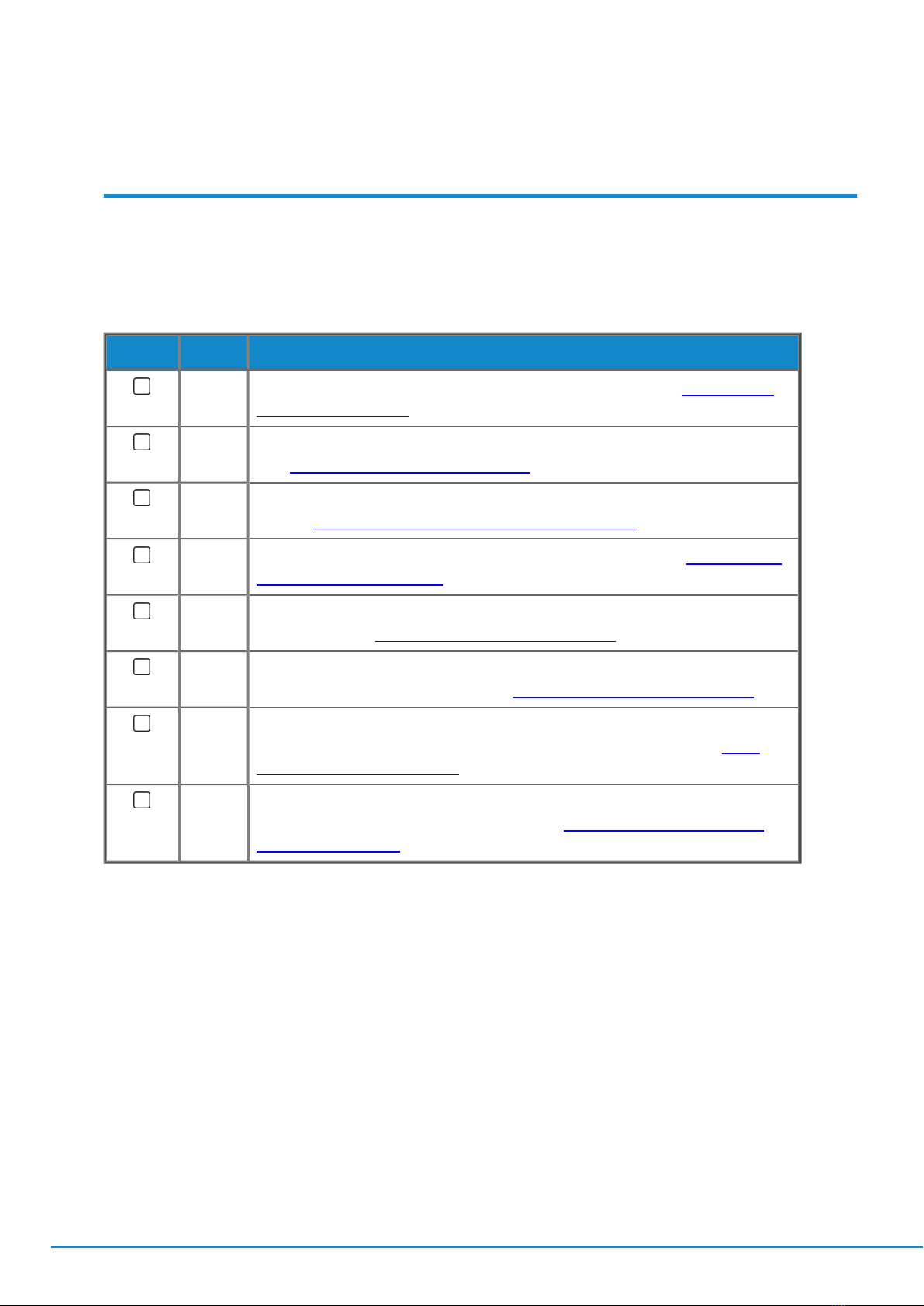
Check Task Description
1Configure the SFP+ IPaddress for use in the test network using either DHCPor
by supplying a static IPaddress. See:
"SFP Setup Management Interface" on
page3-3
2Select the correct SFPMode. See:
"SFPMode & Management" on page3-1
3Configure PTPby setting the PTP Communication mode and Domain number.
See:
"Setting-up Precision Time Protocol (PTP)for 2110 Decap Flows" on page4-6
or
"Setting-up Precision Time Protocol (PTP)for 2110 Encap Flows" on page5-6
.
4Configure NMOSusing either MNSETor a similar control application (if using
NMOS.) See the
MNSETUser Guide
.
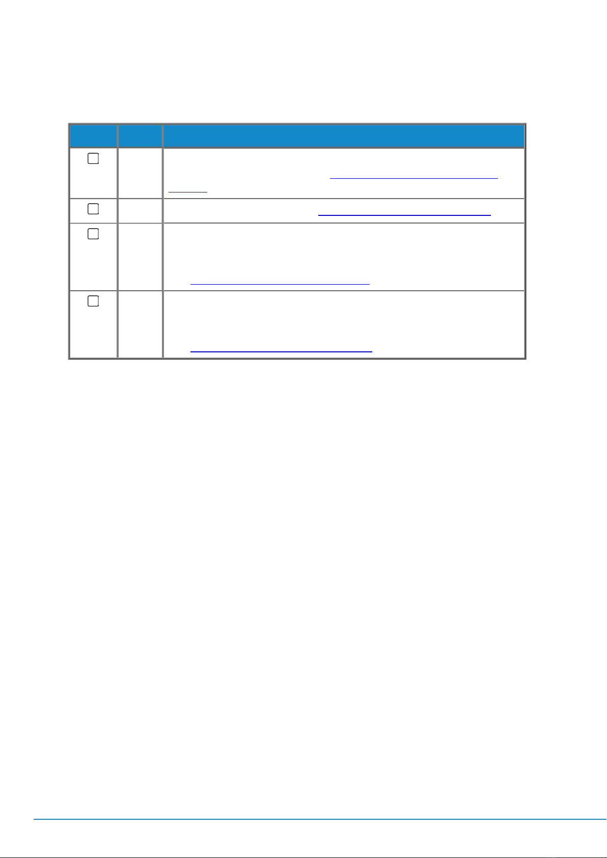
5For 2110 Encap, configure the following:
lGenerator or SDI-to-IP Gateway.
lVideo Flow(s):Set destination IPAddress and enable flow(s) etc.
lAudio Mapping.
lAudio Flow:Set destination IPAddress and enable flow(s) etc.
lANC Flow:Set destination IPAddress and enable flow(s) etc. (if
using the gateway)
lOptionally set the Source IPaddress to match the SFPManagement
IPaddress using the Copy Management Source IP button.
lOptionally enable the synchronizer on the SFP Setup page.
See:
"2110 Encap Video Flows" on page5-2
and
"2110 Encap: Setup Other Flows
and PTP" on page5-4
.
6For 2110 Decap, configure the following:
lConfigure the Video Flow(s): Set Destination Multicast IP Address for
Video, Audio and ANC and enable flow(s).
lConfigure the Audio Mapping.
lConfigure the Audio Flow:Set source IPAddress and enable flow(s)
etc.
lConfigure the ANC Flow: Set source IPAddress and enable flow(s)
etc.
See:
"2110 Decap Video Flows" on page4-2
and
"2110 Decap:Setup Other Flows
and PTP" on page4-4
.
Page 1-6
PHABRIX Sx TAG
Quick Start Guide