Starrett DFC-2 User manual

Trust Is In The Name Quick Reference Guide
PKG08812- QRGDFC

2 PKG08812-QRGDFC 01/18 PDF
READ THIS MANUAL BEFORE USING THE INSTRUMENT
ANTES DE UTILIZAR EL INSTRUMENTO,
LEA ATENTAMENTE ESTE MANUAL
LIRE CE MANUEL AVANT D'UTILISER L'INSTRUMENT
LEIA ATENTAMENTE ESTE MANUAL ANTES
DE UTILIZAR O INSTRUMENTO
使用仪器前请阅读本操作手册
DIESES HANDBUCH VOR DER VERWENDUNG
DES MESSGERÄTS LESEN
LEGGERE ATTENTAMENTE QUESTO MANUALE PRIMA
DI UTILIZZARE QUESTO STRUMENTO

PKG08812-QRGDFC 3
DFC DIGITAL FORCE CONTROLLER
QUICK REFERENCE GUIDE

4 PKG08812-QRGDFC
TABLE OF CONTENTS
PAGE
Introduction 6
Keypad and Navigation 8
On/Off/Menu Key 8
Zero Key 8
Softkey 1 8
Softkey 2 8
Controller Display Formats 11
Using Tolerance Limits 12
Saving Results 12
Clear Results from Memory 13
View Statistics 13
Export Results 13
Gage Setup 13
Charging Battery 14

DFC DIGITAL FORCE CONTROLLER
THIS IS A STARRETT QUICK REFERENCE GUIDE
FOR THE DFG DIGITAL FORCE CONTROLLER.
ALL SPECIFICATIONS IN THIS DOCUMENT
ARE CORRECT AT TIME OF PRODUCTION AND
ARE SUBJECT TO CHANGE. PLEASE CONTACT
STARRETT FOR FURTHER INFORMATION.
PKG08812-QRGDFC 5

6 PKG08812-QRGDFC
ENGLISH
Thank you for choosing the DFC Force Controller.
This Quick Reference Guide is an overview of the basic
functions available with your instrument. For detailed
instructions on instrument setup and operation, please refer
to the electronic user manual. You may download a copy
of the user manual at http://www.Starrett.com/u?dfc-um.
INTRODUCTION
The DFC may be used as a classic digital force gage. It may
also be used as a digital controller when connected to the
FMM Digital Force Tester.
The DFC, as a controller, is the only gage available that
lets you setup an automated test, including the operating
parameters of the force tester. Configure speed and
distance limits through the DFC.
STARRETT DFC ADVANCED FORCE GAGE
SPECIFICATION DFC
Accuracy, Full Scale 0.1%
Data Sampling (Hz) 25,000
Display Resolution 10,000:1
Safe Overload, Full Scale 200%
Maximum Tare 10%
COMMUNICATIONS
Bluetooth®Yes
USB 2.0 Yes
RS-232 Yes
Digital I/O 2 channels
Memory, saved results max. 99
OPERATING MODE
Machine Control1Yes
Real Time Yes
Peak Compression Yes
Peak Tension Yes
Load Limit Yes
Break Limit Yes
Load Average Yes
Load-Time Average Yes
Cyclic Count, Max. 99,999
Cyclic Duration, Max. 27 Hrs.
Hold Duration, Max. 27 Hrs.
Coefficient of Friction Yes
POWER, ENVIRONMENTAL
Battery Type Lithium Ion
Battery Life, @ 20% brightness >30 hours
Charge Time, using 110/240V Mains <3 hours
Display (OLED) 320 x 240
Operating Temperature 40°F to 110°F
(4°C to 43°C)
Thread, for adapters (Metric) M6, M10
Instrument Weight (approx.) 3 lbs
(1.36 kgs)
CE COMPLIANCE
EN61010-1 Safety for Electrical Equipment Yes
EN61000-6-3 EMC Generic Emissions Yes
EN61000-6-1 EMC Generic Immunity Yes
NOTES
1. Machine control is exclusive to the DFC. When
connected to the FMM digital force tester,
configuration of force gage and tester is
performed through the gage.

PKG08812-QRGDFC 7
ENGLISH
DFC - ADVANCED FORCE CONTROLLER
MODEL
LOAD CAPACITY FULL SCALE DEFLECTION THREAD ACCESSORY
N KGF LBF OZF GF IN MM MM KIT
DFC-2 10 1 2 32 900 0.013 0.33 M6 x 1-6H SPK-FG-A
DFC-5 25 2 5 80 2,200 0.007 0.18 M6 x 1-6H SPK-FG-A
DFC-10 50 5 10 160 5,000 0.006 0.15 M6 x 1-6H SPK-FG-S
DFC-20 100 10 20 320 9,000 0.008 0.20 M6 x 1-6H SPK-FG-S
DFC-50 250 25 50 800 23,000 0.015 0.39 M6 x 1-6H SPK-FG-S
DFC-100 500 50 110 1,600 45,000 0.024 0.60 M6 x 1-6H SPK-FG-S
DFC-200 1,000 100 225 - - 0.021 0.54 M6 x 1-6H SPK-FG-M
DFC-500 2,500 250 550 - - 0.028 0.70 M10 x 1.5-5H SPK-FG-L
NOTES
Load measurement accuracy is ±0.1% of load cell capacity. Display resolution is 10,000:1.
3.30 (83.8)
Thread
0.91 (23.0)
1.63 (41.3)
1.70 (43.2)
2.00 (50.8)
2.00 (50.8)
0.55 (14.0)
0.50 (12.7)
0.31 (8.0)
7.50 (190.5)
2.25 (57.2)
A
A
M4x0.7-6H 0.30
Ø0.20 0.18
8 PKG08812-QRGDFC
ENGLISH
KEYPAD AND NAVIGATION
The DFC keypad is multi-functional. There are four keys.
ON/OFF/MENU KEY
This key is used to power the gage on/off. Press to
power the gage on. Press and hold for 3 seconds to
power the gage off.
This key is also used to access the Setup Menu. When
the gage is powered ON, press to access the Setup Menu.
This key is also used to navigate UP when in the
Setup Menu. p
ZERO KEY
This key is used to zero the displayed values. Press
to zero load and if connected to the FMM digital force
tester, zero distance.
This key is also used to navigate DOWN when in the
Setup Menu. q
SOFTKEY 1
This is the left arrow key. It is used to move out of a
setup when in the Setup Menu. t
This key may also be mapped to a specific function.
The Setup Menu has a Key setup function where you
may assign how Softkey 1 performs. For example, you
can assign a SAVE function to the key. When pressed,
the measured values are "saved" to memory.
SOFTKEY 2
This is the right arrow key. It is used to move in to a
setup when in the Setup Menu. u
Like the Softkey 1, it also may be mapped to a specific
function. For example, you can assign a MODE
function to the key. Pressing the key can change the
operating modes of the gage. You can switch from
Real Time to Peak Tension by pressing Softkey 2.
DISPLAY LAYOUT
The force gage features a high-resolution OLED color
display with adjustable backlight. The backlight may
be adjusted from a setting in the Main Menu.
The DFC features a primary and secondary
display window.
DISPLAY TYPES
PRIMARY DISPLAY SECONDARY DISPLAY
Real Time Peak Measurement
Peak Tension Real Time Measurement
Peak Compression Real Time Measurement
Average Peak Measurement Preload to
Start Average
Average (Functional Capacity) Peak MeasurementTime Duration
Static COF Kinetic COF
Kinetic COF Static COF

PKG08812-QRGDFC 9
ENGLISH
lbf
7
22.29
19.24
lbf
5.71
5.66
4
21.10
21.06
7
lbf
lbf
16.84
0.00
16.89
7
Shown: Real Time view showing Peak Compression
Real time load being
placed on load cell
Compression Direction
Peak/Max Compression
Real Time Mode Indicator
Shown: Peak Tension view
Peak Tension Mode Indicator
Real Time value
Tensile Direction
Peak/Max Tension
Shown: Peak Tension view with Tolerance result
Peak Tension Mode Indicator
Real Time value
Shown: Peak Compression view
Peak Compression Mode Indicator
Real Time value
Compression
Direction
Peak/Max Compression
10 PKG08812-QRGDFC
ENGLISH
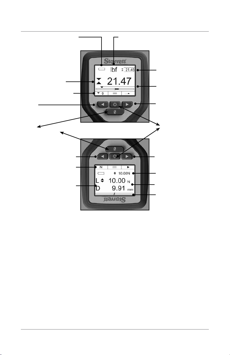
On/Off/Menu key
Use to power gage ON/OFF
Use to access the SETUP MENU
Use to navigate UP
Softkey 1
Associated with above Function
Use to navigate LEFT and move out
of setup option.
Softkey 2
Associated with above Function
Use to navigate RIGHT and INTO setup option
Zero key
Use to zero the display
User to tare the force gage
Use to navigate DOWN
Load Bargraph
Shows active load on sensor.
Shows direction of load.
Primary Result
Shows load direction using a symbol for
Tension or Compression.
Secondary Display
Unit of Measure
Shows unit of measure for displayed results.
Battery Status
Shows remaining battery life.
Shows functions mapped to softkeys
1 and 2. Menu function is always
center key.
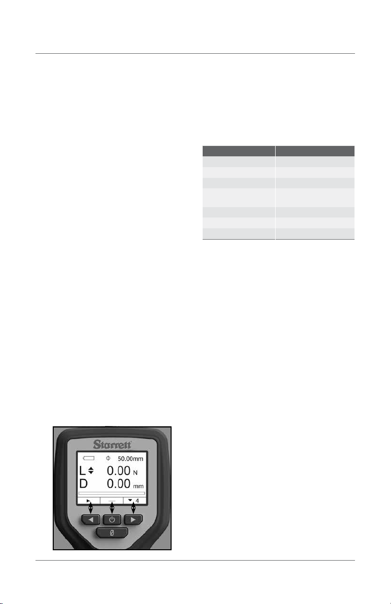
Shown: Display in Classic mode
Shown: Display in Controller mode used with FMM Test Frame
Shows Load measured by load cell
Shows Distance measured by encoder
on the FMM Test Frame.
Shows Load unit of measure.
Shows Distance unit of measure.
Load Bargraph
Shows active load on sensor
Shows direction of load
Softkey 1
Associated with above Function
Use to navigate RIGHT and INTO setup option
Softkey 2
Associated with above Function
Use to navigate LEFT and move out of setup option.
Shows functions mapped to softkeys 1 and 2.
Menu function is always center key. Shows setpoint target that completes
the test method.
PKG08812-QRGDFC 11
ENGLISH
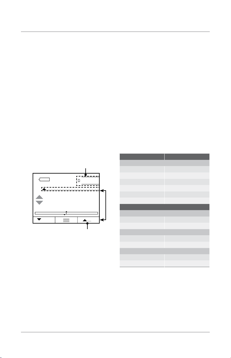
Shown: Functional Capacity result
Shown: COF result
Average Mode Indicator
33.450
33.45
5
µ
µ
17.055
s
k
Average Mode Indicator
Static COF
Kinetic COF
7.15
N
4
7.15
8.1
3.65
lbf 8.71
1.00
9
Average Mode IndicatorShown: Average view
Average Load Average Load
Start Load
Countdown TimerAverage Load
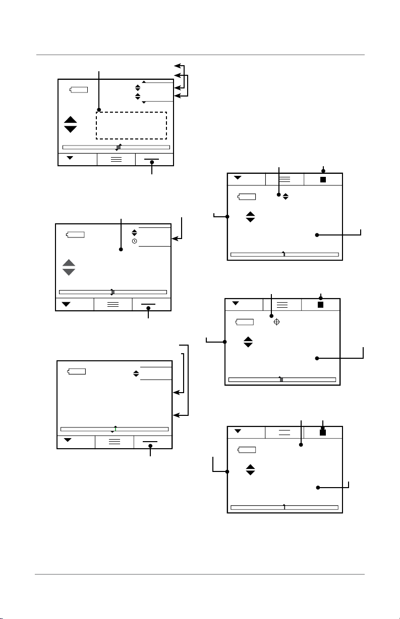
CONTROLLER DISPLAY FORMATS
As a Controller, the DFC will display both load and
distance information and results. The gage will serve
is the universal interface for the "system" and will be
used to setup the force gage and the tester.
The DFC force gage will display load information, as
measured by the load cell.
The DFC force gage will display distance information,
as measured by the FMM digital force tester.
Shown: Load Limit Test results
Shown: Distance Limit Test results
Shown: Break Limit Test results
L
16.55
100.00N
5
N
mm
16.64
D
L 27.45
50%
5
N
mm
28.28
D
L8.80
50.00mm
5
N
mm
8.78
D
Start/Stop Test SoftkeyLoad Limit Target
Active Load
Active Distance
Distance Limit Target Start/Stop Test Softkey
Active Load
Active Distance
Break Limit Target Start/Stop Test Softkey
Active Load
Active Distance
12 PKG08812-QRGDFC
ENGLISH
USING TOLERANCE LIMITS
Use tolerances to setup "pass" and "fail"
measurements. You may specify a Limit 1 and a
Limit 2 to create a tolerance band. Measured results
that equal or fall within the range created by the two
limits are considered "pass" results. If the measured
result falls outside the band created by the two
Limits, the result is considered a "fail" result. A "fail"
results displays in RED.
Press qMove to TOLERANCE
Press uSelect ENABLE
Press qMove down to LIMITS
Press qMove down to LIMIT 1
Press uSelect Limit 1 value using qp
Press tMove out of Limit 1
Press qMove down to LIMIT 1
Press uSelect Limit 2 value using qp
Press tMove out of LIMIT 2
Press tMove out of TOLERANCE
SAVING RESULTS
The DFC feature an internal memory for saving
results for the purpose of calculating and displaying
statistics. You may save up to 99 individual results
in memory.
To save results to memory, you must configure
a softkey with the SAVE function. Press the SAVE
softkey to save the displayed results to memory.
Results saved to memory MUST be of the same type.
You cannot have mixed type results. For example, you
cannot save tension results with COF results. Results
MUST be of the same type.
Results obtained using the TESTS feature are saved in
pairs. For each test, there is a Load and Distance result
(L-D). You cannot save results from different types of
tests. For example, you cannot save results from a
Load Limit test with results from a Break Limit test.
Each load-distance pair of results must have come
from the same test type: Load, Distance or Break.
lbf
5.71
5.66
4
Shown: Peak Tension view with Tolerance result
Peak Tension Mode Indicator
Real Time value
RESULT TYPE MEMORY TYPE
MODES
Real Time Real Time
Tension Peak Tension Peak
Compression Peak Compression Peak
Average Average
Static COF Static COF
Kinetic COF Kinetic COF
TESTS
LOAD LIMIT TEST
Distance @ Limit Distance @ Limit
Load Limit Load Limit
DISTANCE LIMIT TEST
Load @ Limit Load @ Limit
Distance Limit Distance Limit
BREAK LIMIT TEST
Load Max (Peak Load) Load Max (Peak Load)
Distance @ Load Max Distance @ Load Max

PKG08812-QRGDFC 13
ENGLISH
MEMORY
Press pfor Menu
Press qfor Memory
Press uto Display results from memory
Press uto Clear results from memory
Press uto Export results from memory
Select your Units, press tto exit setup
*You must configure a softkey to display memory and statistics.
ABOUT
Press qfor About
Press uto view the gage’s characteristics, serial
number, overload history and more.
Press tto exit setup
*The About setup is read-only.
TOLERANCE
Press pfor Menu
Press qfor Tolerance
Press uto Enable Tolerance
Press uto setup Limit 1, select Limit 1 value pq
Press uto setup Limit 2, select Limit 2 value pq
Press tto exit setup
COMMUNICATIONS
Press qfor Communications (Comms)
Press uto specify the Data Channel method for exporting
results: USB, RS-232, or BT (Bluetooth®)
Press qto select RS-232
Press qto select RS-232 Baud Rate
Press qto setup direction sign (- default for Compression)
Press qto transmit Units
Press qto transmit Tolerance Limits
Press tto exit Comms setup
KEYS
Press pfor Menu
Press qfor Keys
Press qto specify a Sound for key presses
Press qto specify Softkey 1 function
Press qto specify Softkey 2 function
Press tto exit setup
*Certain gage functions require a softkey to be setup in order
to use the function- Memory, Statistics, Tests, Export (Send)
DISPLAY
Press qfor Display
Press uto setup Auto Off
Press uto setup Backlight Brightness
Press uto setup Flip orientation (required for
TESTS feature)
Press uto setup Radix
Press tto exit Display setup
FILTERS
Press qfor Filters
Press uto specify filter rate
Press tto exit Filter setup
SETTINGS
Press pfor Menu
Press qfor Settings, select Settings Type
TESTS
Press pfor Menu
Press qfor Tests
Press uto Enable Tests
Press qto your Test Method
Press uto enter specific Test Method options
*Refer to the User Manual for detailed instructions on using
the TESTS feature in your DFC.
MODES
Press pfor Menu
Press ufor Modes
Select your Mode, press tto exit setup
UNITS
Press pfor Menu
Press qfor Units
Select your Units, press tto exit setup
Management of the DFC memory is important to
ensure correct statistical analysis. Always clear old
results that are from a different test method.
CLEAR RESULTS FROM MEMORY
Results in memory may be cleared individually
or collectively. To clear an individual result from
memory, go to the STATS view. Select the results you
want to clear. Select the "X" (delete) key.
To clear all results from memory, go to the Memory
setup and select CLEAR. This will erase all results for
the gage's memory.
VIEW STATISTICS
You must configure a softkey with STATS to view
statistics. When results are saved to memory, you
press the STATS softkey to view results in memory
and the statistics for those results.
EXPORT RESULTS
You must configure a softkey with SEND to export
to an external device via Bluetooth, RS232 or USB.
Press the SEND softkey to export the displayed result.
GAGE SETUP

14 PKG08812-QRGDFC
ENGLISH
MEMORY
Press qfor Password
Press uto Enable a Password
Press pq to select the Passcode
Press tto exit setup
LANGUAGE
Press qfor Language
Press qto your preferred display language
Press tto exit setup
CHARGING BATTERY
Connect the USB cable supplied with your DFC to the
USB connector at the base of the gage. Connect the
opposite end of the cable to the USB connector on a
source device, i.e., personal computer, USB adapter.
If the DFC is connected to an FMM test frame
and power to the frame is ON, the DFC battery is
continuously charged.
Communicating with External Devices
The DFC can communicate using Bluetooth, USB 2.0
and RS-232. Select the Data Channel type to be used.
PROTOCOL WHERE TO USE
Bluetooth®Print via Bluetooth printer
Export data to an external device
USB 2.0
Charge DFC Battery
Upload firmware and new features to DFC
from a PC
Export data to a printer
Export data to a PC
RS-232
Communicate with a serial printer
Communicate with a serial external computer
or hard drive
Control Controls the crosshead direction and velocity
the FMM from the DFC gage
Gage Setup Menu Structure
RS-232USB 2.0
MODES UNITS MEMORY TESTS TOLERANCE KEYS SETTINGS
Real Time ozf Display Enable Enable Enable Comms
Peak Tension lbf Clear Load Limit Limit 1 Softkey 1 Data Channel
Peak Compression gf Export Type Limit 2 Send RS-232
Averaging kgf Target Sound Units Xmit Comp -
Time Avg N Speed Save Xmit Units
COF User Distance Limit Mode Xmit TOL
Type Stats Display
Target Start/Stop Auto Off
Speed Return 0 Backlight
Break Limit Softkey 2 Flip
Type Send Radix
Minimum Break Units Filter
% Drop Save About
Auto 0 Mode Password
Auto Return Stats Language
Auto Save Start/Stop English
Return 0 Deutsch
Espanol
Portugues
Francais
Italiano
Chinese
Russian
Polski
Czech

PKG08812-QRGDFC 15
NORTH AMERICA
WWW.STARRETT.COM
ATHOL, MA, USA, 01331-1915
EUROPE & ASIA
WWW.STARRETT.CO.UK
JEDBURGH, SCOTLAND, TD8 6LR
SOUTH & CENTRAL AMERICA
WWW.STARRETT.COM.BR
13306-900, ITU, SP, BRASIL
CNPJ 56.994.700/0001-01
CHINA
WWW.STARRETT.COM.CN
USER MANUALS AVAILABLE ONLINE
AT STARRETT.COM

Starrett.com
This manual suits for next models
7
Table of contents
Other Starrett Test Equipment manuals

Starrett
Starrett 3840 Series User manual

Starrett
Starrett SR160 User manual

Starrett
Starrett SR200 User manual

Starrett
Starrett MTH-330 User manual

Starrett
Starrett SR300 User manual

Starrett
Starrett MTH-550 User manual

Starrett
Starrett SR160 User manual

Starrett
Starrett SR160 User manual

Starrett
Starrett MTH-110 User manual


