8
BUTTONS
PHACON
3D LIFE MODELING & SIMULATION
Buttons
3
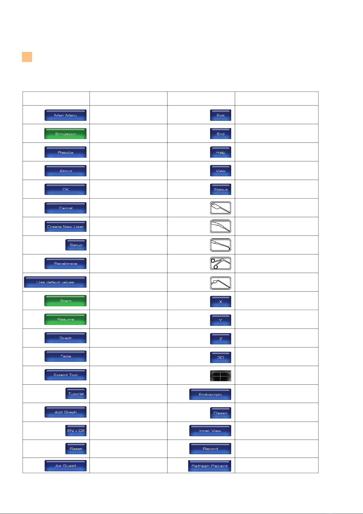
Button Definition
Button Definition
Login as guest. Reload detected patient CT-data.
Access the MAIN MENU screen to view
major menu options.
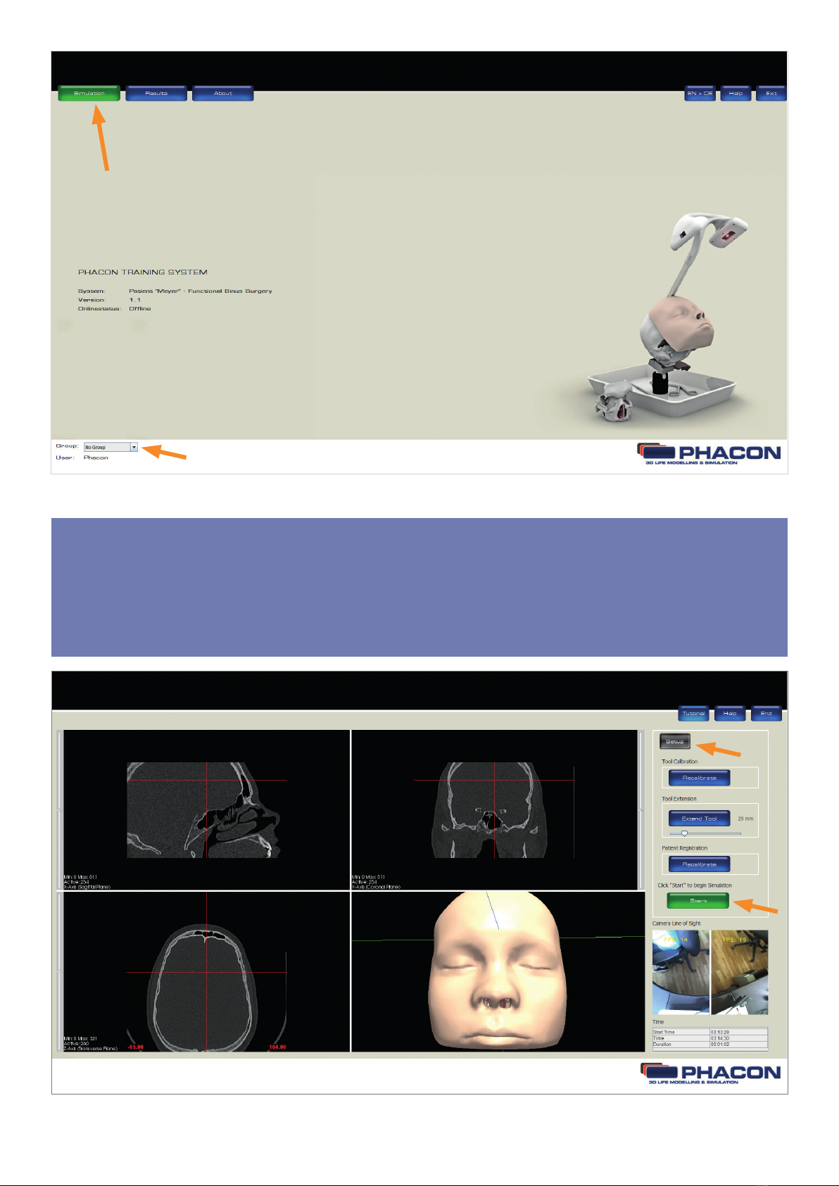
Access the SIMULATION screen to begin
a training session.
Access the RESULTS screen to view and
compare the training session data.
Access the ABOUT dialog box to view
hardware and software information.
Accept inputs, changes or selections
and return to the previous screen.
Reject inputs, changes or selections and
return to the previous screen.
Access the CREATE NEW USER dialog
box to create a new user profile, user
name and password.
Access the SETUP panel to perform
calibration of an instrument or patient.
Initiate the calibration of instruments or
patient from the SETUP panel.
Select the factory default calibration set-
tings programmed for the instrument or
Patient.
Begin a SIMULATION or training session
from the SETUP panel.
Continue a SIMULATION or training
session from the SETUP panel.
Access and view the training session
results in a graphical format.
Access and view the training session
results in a tabular format.
Virtual extension of the instrument.
Open a tutorial.
Add a graph in the result screen.
Select or toggle the language for the
software (German / English).
Reset the default settings for brightness,
contrast and slice position in the 4
windowpane in the simulation mode.
Close and exit the program.
End the SIMULATION or training
session.
Access the HELP dialog box to view
instructions for use information.
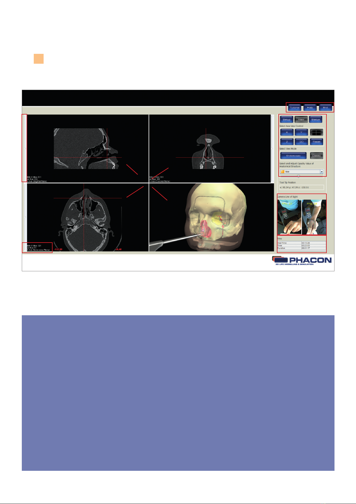
Access the VIEW panel to select or
modify a screen view or perspective.
Access the STATUS panel to view the
number of injured risk structures during
a training session.
Select the POINTER for recalibration
and use.
Select the angled drill for recalibration
and use.
Select the ballprobe for recalibration
and use.
Select the blakesley for recalibration
and use.
Select the suction device for recalibration
and use.
Access the sagittal view of the skull CT
data as a full screen display.
Access the coronal view of the skull CT
data as a full screen display.
Access the transversal view of the skull
CT data as a full screen display.
Access the 3-D view of the Patient and skull
as a full screen display.
Return to the default 4-windowpane
screen view.
View a navigated instrument in the 3-D
windowpane as if a virtual camera was
mounted on the tip of the instrument.
View a navigated instrument without the
virtual camera option.
Access the camera view onto the transparent
cochlea.
Record a video of the camera view of the
cochlea.