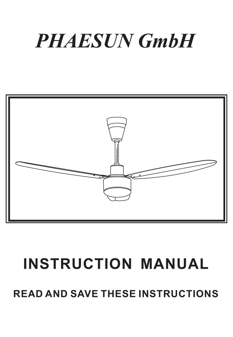
Phaesun DC24-3-WC Technical document

DMontage- und Bedienungs-
anleitung 8 - 10 GB Mounting and operating
manual 11 - 13
FInstructions de montage et de
service 14 - 16 I Istruzioni per il montaggio
e l´uso 17 - 19
DECKENVENTILATOR
CEILING FAN
VENTILATEUR DE PLAFOND
VENTILATORE DA SOFFITTO
301011v4.2
DC24-3-RC
DC24-3-WC

2
24 V DC!
fig. 8
DC24-3-RC
DC24-3-WC

Übersicht der Einzelteile
3
Motor mit Gehäuse
Deckenstange
Montagehalter
Halbkugel
Baldachin
Montagering (fl ache Montage)
Abdeckung
Schraube für Flügel (9x)
Flügelblatt (3x)
Schraube CLS 4x50 (2x)
11 Flügelhalter (3 x)
12 Schraube m. Schei be f. Flügelhalter (6x)
13 Auswuchtsatz
14 Schraube für Baldachin (4x)
12
13
14
DC24-3-RC: 1x
DC24-3-WC: 1x

4
2 x
A:
1.
2.
fi g. A7
Elektr. Anschluss an
das Hausnetz
Electric wiring
diagramm
GB
FR Raccord au réseau
électrique IAllacciamento
elettrico
D
min. 15 kg !
fi g. 1
fi g. A2 fi g. A3 fi g. A4
fi g. A5
fi g. A6
fi g. 8
14
14

5
fig. B3
6 x
B:
fig. B2
fig. B4
6 x
6 x
fig. 8
1.
2.
Elektr. Anschluss an
das Hausnetz
Electric wiring
diagramm
GB
FR Raccord au réseau
électrique
IAllacciamento
elettrico
D
fig. B5 fig. B6
fig. B7 fig. B8
14
14

6
3 x 2 x 3 x 2 x
3 x 3 x 3 x
fig. 9 fig. 10
fig. 11 fig. 12
11
11
12
11
DC24-3-RC
DC24-3-WC

7
1x 2x
1x
DC24-3-RC:
ON/
OFF
DC24-3-WC:

Beschreibung Phaesun-Ventilator
Der DC24-3 Ventilator dient zur Luftumwälzung der Raumluft. Der Einsatz in Maschinen, im
Freien, in Garagen, sowie in feuchten, nassen, feuer- und explosionsgefährdeten Räumen ist
nicht gestattet.
Technische Daten:
Typ DC24-3-WC DC24-3-RC
Nennspannung 24 V DC
Leistung Motor 26,4 (max.)
Schutzklasse/Schutzart I/IP20
Stufen stufenlos 6
Maße Ø x H (mm) ca. 1320 x 410
Abstand Decke-Flügel (mm) ca. 300 mm, kürzbar auf ca. 210 mm
Gewicht ca. 4,9
Technische Änderungen vorbehalten.
Über diese Bedienungsanweisung
Bevor Sie den Phaesun-Ventilator benutzen, lesen Sie bitte die Bedienungsanweisung aufmerk-
sam durch. Bewahren Sie die Bedienungsanweisung griffbereit auf. Geben Sie den PHaesun-
Ventilator nie ohne Bedienungsanweisung an andere Personen weiter.
Zeichenerklärung:
Gefährliche elektrische Spannung Achtung
Warnt den Benutzer vor Schäden, die durch
elektrische Spannung verursacht werden.
Besonderer Hinweis für den Benutzer.
D
8
Achtung! Gerät darf nur vollständig montiert betrieben werden!
- Verpackungsmaterial umweltbewusst und für Kinder unzugänglich entsorgen.
Montage
Gehen Sie nach den Abbildungen fig. 1 - fig. 12 auf den Seiten 4 - 7 vor.
- Den Phaesun-Ventilator auspacken, auf Vollständigkeit (siehe Abbildung Seite 3) und
sichtbare Beschädigungen prüfen.
1. Motor 6. Montagering (flache Montage) 11. Flügelhalter (3 x)
2. Deckenstange 7. Untere Abdeckung 12. Schraube f. Flügelhalter (6x)
3. Montagehalter 8. Schraube für Flügel (9x) 13. Auswuchtsatz
4. Halbkugel 9. Flügelblatt (3 x) 14. Schraube f. Baldachin (4x)
5. Baldachin 10. Schraube (2x)
Alle hier genannten Sicherheitsmaßnahmen im Umgang mit elektrischem Strom erset-
zen ein vernünftiges und umsichtiges Handeln nicht. Es können nicht alle vorstellbaren
potentiellen Gefahren beschrieben werden, die bei der Montage und Inbetriebnahme
Ihres Ventilators entstehen können.

9
Beim Einsatz jeglicher Elektrogeräte sind einige Grundregeln stets zu beachten, darunter im
Einzelnen:
Allgemein
- Die Spannungsangabe auf dem Typenschild muss mit der vorhandenen Netzspannung übereinstimmen.
- Das Hausnetz muss geerdet sein!
- Gerät darf nur vollständig montiert betrieben werden!
Wichtig
Für den elektrischen Anschluss dieses Ventilators wird empfohlen sich an
einen spezialisierten Fachmann zu wenden.
Sicherheitshinweise
Vor Zugang an den Anschluss muss der Strom allpolig abgestellt werden. Der Netzanschluss, an
welchen Sie angeschlossen sind, muss den geltenden Normen entsprechen. Der Festanschluss
muss mit einer Allpoltrennung mit Kontaktabstandsöffnung von mindestens 3 mm versehen
sein. Wir empfehlen, den Anschluss von einem qualifizierten Elektriker vornehmen zu lassen.
Die Struktur der Decke und u. U. der Anschlussdose müssen das Gewicht des Ventilators bei
Bewegung tragen können, d. h. ca. 15 kg minimum. Wählen Sie einen sicheren, ungefährlichen
Ort. Keines der Ventilatorblätter darf sich unter einem Fußbodenabstand von 2,30 m befinden.
Der Ventilator muss richtig geerdet sein. Vor Inbetriebnahme die Montage sowie alle elektrischen
Anschlüsse überprüfen, um jegliche Fall-, Feuer- oder Elektroschock-Gefahr zu verhindern.
Installation Ihres Ventilators
Stellen Sie fest, ob eine Anschlussdose an dem für die Montage vorgesehenen Platz vorhanden
ist. Wenn dies nicht der Fall ist, befestigen Sie den Montagehalter direkt an der Decke mit Hilfe
von Holzschrauben Durchmesser 6 mm, wenn nötig mit Betondübel Durchmesser 8 mm, oder für
Gipsplatten spezielle, dafür geeignete Dübel.
Gehen Sie nach den Abbildungen fig. 1 - fig. 12 auf Seite 4 - 7 vor
- Den Ventilator auspacken und den Inhalt überprüfen. Alle auf der Abbildung dargestellten Teile
müssen enthalten sein.
- Der Montagehalter liegt separat vom Ventilator bei. Den Montagehalter mit Hilfe der Schrauben
und Unterlegscheiben an dem Deckenauslass der Decke montieren. Für einen sicheren Betrieb
Ihres Ventilators stellen Sie bitte sicher, dass der Montagehalter fest sitzt und eben ist.
- Die Aufhängung muss lotrecht erfolgen.
- Den Deckenhalter an der Decke befestigen.
- Vor elektrischen Arbeiten den Strom abschalten.
- Den elektrischen Anschluss Ihres Ventilators wie auf Seite 2 in fig. 8 angegeben vornehmen.
- Die Flügel mit Hilfe der Schrauben am Motor montieren. Wenn Sie mehrere Ventilatoren instal-
lieren, achten Sie darauf, dass die verschiedenen Flügel nicht untereinander verwechselt werden.
Die Flügel sind nach Gewicht gruppiert, um Schwingungen zu verhindern.
- Nach kompletter Montage Ihres Ventilators vergewissern Sie sich, dass alle Anschlüsse ein-
wandfrei sind und die Schrauben und Muttern festgezogen sind.
Betrieb Ihres Ventilators
Vergewissern Sie sich, dass die Montage vollkommen beendet ist.
Zur Regulierung der Drehzahl können Sie den optional angebotenen Stufentrafo oder eine ge-
eignete Fernbedienung verwenden. Verwenden Sie niemals einen Dimmer oder einen Phasenan-
schnitt- oder Phasenabschnittregler.

Wichtig
Selbst wenn Ihr Ventilator sich über einem Fußbodenabstand von mehr als 2,30 m befindet,
müssen Sie darauf achten, dass die Flügel frei drehen können und keine Gegenstände in deren
Radius kommen können.
Wartung Ihres Ventilators
Sie verlängern die Lebensdauer Ihres Ventilators, indem Sie folgende Hinweise beachten:
1. Die verschiedenen Teile der Deckenbefestigung und des Halters 2 mal pro Jahr überprüfen. Die
Komponenten des Ventilators können auf einige Teile Spiel haben.
2. Benutzen Sie niemals Wasser zum Reinigen des Motors oder anderer elektrischer Teile; dies
würde zu einem Kurzschluss führen.
3. Zum Reinigen der Blätter und des Gehäuses ein weiches Tuch verwenden.
4. Ein Fetten der Lager ist nicht notwendig, die Lager sind dauergeschmiert.
Vergessen Sie nicht zu überprüfen, dass der Anschluss der Erdungsleitung an die Ausgangsklem-
me und zwischen allen metallischen Teilen richtig vorgenommen wurde (die Steckkontakte an
jedes Erdsymbol anschließen).
Hilfe bei Störungen
Störung Abhilfe
Der Ventilator
setzt sich nicht in
Gang.
Überprüfen Sie die Sicherungen des Hauptnetzes und der anderen An-
schlüsse.
Überprüfen Sie den Anschluss des Ventilators an den Netzanschluss.
Überprüfen Sie, ob die Sicherungen im Anschlusskasten richtig eingefügt
sind.
Der Ventilator
macht Geräusche.
Überprüfen Sie, ob alle Schrauben festgezogen sind.
Geben Sie dem Ventilator und den Lagern eine Einlaufzeit von 24 Stunden.
Die meisten Geräusche verschwinden nach dieser Zeit.
Der Ventilator
schwingt zu stark.
Alle Blätter wurden gewogen und nach Gewicht gruppiert. Die Dichte kann
variieren und dadurch Schwingungen erzeugen, selbst wenn alle Blätter
das gleiche Gewicht haben. Die folgende Methode kann dazu beitragen,
die meisten Schwingungen zu verhindern. Die Schwingungen nach jedem
Vorgang überprüfen. Beachten Sie bitte, dass kleine Schwingungen normal
sind und kein Problem darstellen.
Die meisten Schwingungen entstehen, wenn einer der Flügel nicht mehr
auf die anderen ausgerichtet ist. Die Ausrichtung der Blätter kann leicht
mit Hilfe eines flachen Lineals festgestellt werden. Das Lineal senkrecht
an die Decke und zur Blattspitze ansetzen. Den Abstand zwischen Blatt-
seite und Decke markieren. Drehen Sie die Blätter langsam per Hand und
nehmen Sie die gleichen Messungen an den anderen Blättern vor. Wenn
eines der Blätter nicht richtig ausgerichtet ist, können Sie dies beheben,
indem Sie die Halterungen leicht nach oben oder unten drücken, um sie
auf die anderen auszurichten.
Überprüfen Sie, ob der Deckenhalter fest mit der Decke verankert ist.
Achtung: Öffnen des Gerätes und Reparaturen dürfen nur durch einen Fachmann durchgeführt werden!
D
10

About this operating instructions
Before using the Phaesun fan, read the operating instructions carefully. Keep the operating
instructions within reach. Never pass the fan onto another person without the operating
instructions.
Explanation of symbols:
Dangerous electric voltage Careful
Warn the user of the dangers caused by
electricity
Particular note for the user.
Caution! Only operate the unit when completely assembled!
- Dispose of packaging taking the environment into account and keep out of the reach of children.
Assembly
Please proceed as per figures 1 - 12 at Page 4 - 7 of these operating instructions.
GB
11
When dealing with electricity, just conforming to all the safety and precautionary
measures can not describe every danger situation. They do not replace sensible pro-
cedures and care, which you have to take into account when first initiating and then
running your fan.
When using any electric units, several basic rules have to always followed, as detailed
below:
Describing the Phaesun fan
The fan is for circulating room air. Their use in machines which are outside and unprotected, in
garages, in moist or wet rooms or rooms in danger of fire or explosion, is not permitted.
Technical data:
Type DC24-3-WC DC24-3-RC
Mains voltage: 24 V DC
Power motor (W): 26,4 (max.)
Protection clas: I/IP20
No of speeds: continuous 6
Dimensions Ø x H (mm) ca. 1320 x 410
Dist. ceiling - blades (mm) approx. 300, or approx. 210
Weight (kg): approx. 4,9
- Unpack the Phaesun fan, check if everything is present (see page 3) and for visible signs
of damage.
1. Motor block 6. mounting ring 11. Bladeholder arms (3x)
2. Assembly rod 7. Lower cover 12. Srcew for bladeholder (6x)
3. Mounting bracket 8. Screw for blade (9x) 13. Balancing kit
4. Ball assembly 9. Blade (3x) 14. Screw for canopy (4x)
5. Canopy 10. Screw (2x)

General
- The voltage details on the nameplate are to conform with the available mains voltage.
- The building mains must be earthed!
- Only operate the unit when completely assembled!
Important
- It is recommended that a specialist electrician is used for making the electrical connection
to this fan.
Safety instructions
Before accessing the connection, all current carrying conductors are to be isolated.
The mains connections to which you are connected is to comply with current specifications.
The fixed wire connection is to be provided with a multi-pole isolator with contact gaps of at
least 3 mm. We recommend that the connection be made by a qualified electrician.
The construction of the holder and the output box is to be able to bear the weight of the fan
when being moved, ie, about 15 kg minimum. Chose a secure, safe location. None of the fan
blades are to be less than 2.30 m from the ground. The fan is to be correctly earthed.
Before first using the setup, all electrical connections are to be checked in order to prevent any
fall, fire or electric shock.
Installing your ventilator
Ascertain that a mounting bracket is available at the intended mounting point.
If this not the case, then fix the mounting bracket directly to the ceiling using wood screws
having a diameter of 6 mm and, if necessary, 8 mm diameter concrete anchors or special plugs
suitable for plaster boards.
Proceed as per fig. 1 - fig. 12 shown on page 4 - 7
- Unpack the ventilator and check the contents. All the parts shown in the drawing are to be
present.
- The mounting plate is separate from the fan.
Assemble the mounting plate using the screws and washers to the ceiling outlet.
In order to assure a safe operation of your fan, make sure that the mounting plate is firmly
seated and is level.
-The attached part is to be vertical.
- Fix the support hook to the ceiling.
- Disconnect the electricity before working on the electrics.
- Make the electrical connection to your fan as per Figure on page 2 in fig. 8.
- Fix the blades to the motor using the bolts.
- If you are installing several fans, make sure that the various blades are not mixed up,
- The blades are grouped according to weight, in order to avoid vibration.
- After finishing assembling the fan, make sure that all connections are in order and that all nuts
and bolts are tightened.
Operating your fan
Make sure that the assembly has been completely finished.
Use a stepped transformer for controlling the speed, optional extra. Never use a dimmer or a
phase angle or phase inverse angle controller.
GB
12

Important
Even if your fan is more that 2.30 m above the ground, care must still be taken care that the
blades are free to turn and no objects can enter their radius of action.
Maintaining you fan
You increase the life of your fan by heeding the following notes:
1. Check the various ceiling fixing parts and bracket twice a year.
Some of the parts on the fan components can have play.
2. Never use water for cleaning the motor or other electrical parts; this would lead to a short
circuit.
3. Use a soft cloth for cleaning the blades and housing.
4. Greasing the bearings is not necessary, the bearings are permanently lubricated.
Do not forget to check that the earth connection lead has been correctly connected to the
output terminal block and between all metal parts (connect the push-on contact to every earth
symbol).
GB
13
Notes for removing faults
Fault Remedy
The fan does not
start.
Check the fuses/trips at the main box and other connections.
Check the fan connection to the mains.
Check that fuses/trips in the connection box are correctly inserted.
The fan is noisy. Check that all bolts and screws have been tightened.
Run in the fan and the bearings for 24 hours. Most noises disappear after
this time.
The fan vibrates
too much.
All blades have been weighed and grouped according to weight.
Their density can vary and therefore cause vibration even when all blades
are of the same weight. The following methods can contribute to preventing
most vibrations. Check the vibration before each procedure. Please note
that a small amount of vibration is normal and does not pose a problem.
Most vibrations occur when one of the blades is not in alignment with
the others. Aligning the blades is simply carried out with the aid of a flat
ruler. Place the ruler vertically upwards against the ceiling and alongside
the blade tip. Mark the distance between the blade side and ceiling.
Turn the blades slowly by hand and carry out the same measurements with
the other blades. If one of the blades is not correctly aligned, it can be
remedied by lightly pressing their holders upwards or downwards in order
to align them with the others.
Check that the mounting plate is firmly anchored to the ceiling.
Important:
Opening up and repairing the unit may only be carried out by a specialist!

A propos du mode d’emploi
Lisez attentivement le mode d’emploi avant d’utiliser le ventilateur Phaesun. Conservez-le à
portée de la main. Ne donnez jamais le ventilateur à une autre personne sans son mode d’emploi.
Explication des symboles:
Tension électrique gratuite Attention
Met en garde l’utilisateur des dommages
imputables à la tension électrique
Remarque particulière à l’intention de
l’utilisateur.
Attention! L’appareil ne doit être utilisé qu’entièrement assemblé!
- Débarrassez-vous de l’emballage dans le respect de notre environnement et de manière à ce
qu’il reste en dehors de la portée des enfants.
Montage
Veuillez suivre les indications Figure 1 - 12 à page 4 - 7 du présent mode d’emploi.
FR
14
Toutes les mesures de sécurité contenues dans ces instructions ne peuvent pas décrire
toutes les situations de risques en liaison avec l’utilisation de la tension électrique.
Elles ne peuvent remplacer l’approche et la prudence raisonnables requise dans la mise
en service et l’utilisation de votre ventilateur.
L’utilisation de tout type d’appareillage électrique implique quelques règles de base à respecter
systématiquement qui sont, entre autres :
Descriptif du ventilateur Phaesun
Le ventilateur sert à la circulation de l’air ambiant. L’utilisation dans des machines non protégées
à l’’extérieur, dans des garages ainsi que des locaux humides, exposés aux risques d’explosion est
interdite. Un moteur puissant entraîne le rotor.
Caractéristiques techniques:
Type DC24-3-WC DC24-3-RC
Tension nominale: 24 V DC
Puissance moteur (W): 26,4 (max.)
Classe de protection: I/IP20
Vitesses: continu 6
Cotes Ø x H (mm) ca. 1320 x 410
Dist. plafond - pales (mm) env. 300, ou env. 210
Poids (kg): env. 4,9
- Déballer le ventilateur Phaesun, vérifier si l’appareil est au complet (voir illustration à
page 3) et ne présente pas de dommages apparents.
1. Bloc moteur 6. anneau de montage 11. Supports de pales (3x)
2. Tige de montage 7. Cache inférieur 12. Vis de Support de pales (6x)
3. Balle 8. Vis de pale (9x) 13. Set d´équilibrage
4. Support de montage 9. Pale (3x) 14. Vis de Cache inférieur
5. Cache supérieur 10. Vis (2x)

Generale
- La tension indiquée sur la plaque signalétique doit correspondre à la tension secteur effective.
- Le réseau électrique domestique doit être mis à la terre !
- L’appareil doit fonctionner sur un support plan et stable.
Important
Nous recommandons de recourir aux services d’un spécialiste pour procéder au branchement
électrique de ce ventilateur.
Consignes de sécurité
L’électricité doit être coupée au niveau de tous les pôles avant tout accès à la connexion. Le
raccordement au réseau par lequel vous êtes relié doit répondre aux normes en vigueur. Le
raccordement fixe doit être doté d’une séparation de tous les pôles avec une distance entre les
contacts d’au moins 3 mm. Nous vous recommandons de confier la réalisation du branchement à
un électricien qualifié. La structure du support et de la boîte de sortie doit pouvoir supporter le
poids du ventilateur en mouvement, soit environ 15 kg minimum. Choisissez un emplacement
sûr et sans danger. Aucune pale ne doit se trouver à une distance inférieure à 2,30 m par rapport
au sol. Le ventilateur doit être correctement mis à la terre. Vérifier le montage ainsi que toutes
les connexions électriques avant la mise en service afin d’éviter tout risque de chute, d’incendie
ou d’électrocution.
Installation de votre ventilateur
Constatez s’il existe un support à l’endroit prévu pour le montage. Dans le cas contraire, fixer
la plaque de montage directement au plafond à l’aide de vis à bois diamètre 6 mm si nécessaire
avec des chevilles pour béton diamètre 8 mm ou des chevilles prévues pour les plateaux de «
Placoplatre ».
Veuillez procéder comme indiqué dans fig. 1 - fig. 12 à page 4 - 7
- Déballer le ventilateur et vérifier le contenu. Toutes les pièces représentées sur les photos
doivent être contenues.
- La plaque de montage est séparée du ventilateur. Monter la plaque de montage à l’aide des vis
et des rondelles sur la sortie du plafond. Pour que votre ventilateur fonctionne en toute sécurité,
veuillez vous assurer que la plaque de montage est solidement fixée et plane.
- La suspension doit être verticale.
- Fixer l’arceau support sur le plafond.
- Couper l’électricité avant tous travaux électriques.
- Procéder au raccordement électrique de votre ventilateur comme indiqué figure 8 à page 2.
- Placer les pales à l’aide des vis sur le moteur. Si vous installez plusieurs ventilateurs, veillez à
ne pas intervertir les différentes pales. Les pales sont groupées en fonction du poids afin d’éviter
les vibrations.
- Après un montage complet de votre ventilateur, assurez-vous que toutes les connexions sont
parfaitement réalisées et serrer bien les vis et les écrous.
Fonctionnement de votre ventilateur
Assurez-vous que le montage soit parfaitement achevé.
Afin de réguler la vitesse de rotation, vous pouvez utiliser le transformateur à gradins proposé
en option. Utilisez un variateur ou une commande par coupures de phases.
15
FR

Important
Même si votre ventilateur se trouve à une distance du sol supérieure à 2,30 m, vous devez veiller
à ce que les pales puissent tourner sans entrave et qu’aucun objet ne se trouve dans leur rayon
d’action.
Entretien de votre ventilateur
Vous prolongerez la durée de vie de votre ventilateur en tenant compte des remarques suivantes:
1. Vérifiez 2 fois par an les diverses pièces de la fixation ou plafond et le support
Les composantes du ventilateur peuvent avoir pris du jeu par endroits.
2. N’utilisez jamais de l’eau pour nettoyer le moteur ou d’autres composants électriques, vous
risquez un court-circuit.
3. Utiliser un chiffon pour nettoyer les pales et le boîtier.
4. Il n’est pas nécessaire de graisser les paliers de roulement, ils sont graissés à vie.
N’oubliez pas de vérifier si le fil de terre a bien été raccordé sur la borne sortie et entre les pièces
métalliques (connectez les contacts sur chaque symbole de terre).
16
FR
Conseils en vue de remédier aux incidents
Incident Remède
Le ventilateur ne
se met pas en
marche.
Vérifiez les fusibles du secteur et les autres connexions.
Vérifiez si le ventilateur est correctement connecté au secteur. ss.
Vérifiez si les fusibles dans la boîte de raccordement sont correctement
posés.
Le ventilateur
émet des bruits.
Vérifiez si toutes les vis sont correctement serrées.
Laissez au ventilateur et aux roulements une période de rodage de 24
heures. La plupart des bruits disparaissent après ce lapse de temps.
Le ventilateur
vibre trop
Toutes les pales ont été pesées et groupées en fonction de leur poids.
La densité peut varier et provoquer des vibrations même si toutes les
pales présentent le même poids. La méthode suivante peut contribuer à
empêcher la plupart des vibrations. Vérifier les vibrations après chaque
opération. Veuillez vérifier si les petites vibrations sont normales et ne
posent pas de problème.
Les vibrations surviennent généralement lors que les pales ne sont plus
alignées entre elles. L’alignement des pales peut être facilement constaté
à l’aide d’une règle plate. Placez la règle à la verticale du plafond et de
l’extrémité de la pale. Marquer la distance entre le côté de la pale et le
plafond. Tournez les pales lentement à la main et effectuez les mêmes
mesures sur les autres pales. Si l’une des pales n’est par correctement
orientée, veuillez corriger ce défaut en poussant les supports vers le bas
ou vers le bas afin des orienter dans l’alignement des autres.
Vérifiez si la plaque de montage est correctement ancrée dans le plafond.
Attention : L’ouverture de l’appareil et les réparations sont l’affaire exclusive d’un spécialiste !

17
Sulle istruzioni per l’uso
Prima di utilizzare il ventilatore Phaesun, leggete con attenzione le relative istruzioni e con-
servatele a portata di mano. In caso di trasferimento del ventilatore a terzi, accludete sempre
le relative istruzioni per l’uso.
Significato dei simboli:
Pericolo tensione elettrica Attenzione
Avverte l’utente del rischio di danno provo-
cato da tensione elettrica.
Avvertenza per l’utente.
Attenzione! L’apparecchio può essere utilizzato solo a montaggio completato!
- Smaltire l’imballo in modo ecologico, tenendolo lontano dalla portata dei bambini.
Montage
Procedete come illustrato alla figuri fig. 1 - fig. 12 a pagine 4 - 7 delle presenti istruzioni.
I
- Rimuovere l’imballo del ventilatore Phaesun. Verificare la completezza del contenuto (vedi
illustr. pagina 3) e l’assenza di danni evidenti.
1. Blocco motore 6. Boccola installazione 11. Staffe di pale (3x)
2. Asta di supporto 7. Coperchio inferiore 12. Vite di staffe di pale (6x)
3. Staffa di montaggio 8. Vite di pale (9x) 13. Set di equilibratura
4. Sfera 9. Pale (3x) 14. Vite di coperchio superiore
5. Coperchio superiore 10. Vite (2x)
Le misure di sicurezza e le precauzioni qui contenute non contemplano tutte le possibili
situazioni di pericolo comportate dalla presenza di corrente elettrica e non possono
certamente sostituire una condotta ragionevole e cauta, che è sempre necessario tenere
durante la messa in funzione e l’esercizio del ventilatore.
L’impiego di alcuni elettrodomestici è sempre necessario osservare alcune regole basilari, in par-
ticolare:
Descrizione del ventilatore Paesun
Il ventilatore svolge funzioni di ricircolo dell’aria nel locale. Non è consentito l’impiego del venti-
latore all’interno di macchinari, in luoghi aperti non protetti, garage e locali umidi o con rischio
d’incendio ed esplosione. La girante è azionata da un potente motore.
Dati tecnici:
Tipo DC24-3-WC DC24-3-RC
Tensione di rete: 24 V DC
Potenza motore (W): 26,4 (max.)
Classe di protezione: I/IP20
Regolazioni velocità: continuo 6
Dimensione Ø x alt.: (mm) ca. 1320 x 410
Dist. soffitto - pales (mm) ca. 300, o ca. 210
Peso: (kg): ca. 4,9

Informazioni generali
- I valori di tensione riportati sulla targhetta devono corrispondere alla tensione di alimentazione.
L’impianto domestico deve essere dotato di messa a terra.
- L’apparecchio può essere utilizzato solo a montaggio completato!
Importante
Per il collegamento elettrico di questo ventilatore si consiglia di rivolgersi ad un tecnico spe-
cializzato.
Istruzioni di sicurezza
Prima di procedere al collegamento, è necessario interrompere l’alimentazione a tutti i poli.
L’impianto di alimentazione al quale ci si collega deve essere conforme alle norme vigenti. Il col-
legamento fisso deve essere dotato di sezionatore onnipolare con distanza di contatto di almeno
3 mm. Si consiglia di affidare le operazioni di collegamento ad un elettricista specializzato. La
struttura del supporto e della scatola d’uscita devono essere in grado di sopportare il peso del
ventilatore in movimento, ovvero almeno 15 kg circa. Per l’installazione, scegliete un luogo
sicuro, che non presenti alcun tipo di rischio. Nessuna delle pale del ventilatore deve trovarsi
ad una distanza da terra inferiore a 2,30 m. Il ventilatore deve essere dotato di messa a terra
conforme. Dopo l’installazione, controllare il montaggio e tutti i collegamenti elettrici, in modo
da evitare eventuali rischi di caduta, incendio o shock elettrico.
Installazione del ventilatore
Controllate se, sul luogo prescelto per l’installazione sia presente un supporto di montaggio.
In caso contrario, fissate la piastra di montaggio direttamente al soffitto, utilizzando viti per
legno del diametro di 6 mm e, ove necessario, tasselli per cemento del diametro di 8 mm, oppure
speciali tasselli per solette in gesso.
Procedete come illustrato nelle fig. 1 - 12 a pagine 4 - 7
- Rimuovere l’imballo del ventilatore e controllare il prodotto. La confezione deve contenere
tutte le parti rappresentate a figura.
- La piastra di montaggio viene fornita separatamente dal ventilatore. Montare la piastra a sof-
fitto, in corrispondenza dei cavi di allacciamento, utilizzando le viti con le relative rondelle. Per
un funzionamento sicuro del ventilatore, accertatevi che la piastra di montaggio sia saldamente
fissata e correttamente allineata.
- Durante il fissaggio, controllare che il ventilatore sia perfettamente a piombo.
- Fissare la staffa di supporto al soffitto.
- Prima di eseguire il collegamento elettrico, interrompere l’alimentazione ai cavi.
- Collegare il ventilatore come indicato fig. 8 alla pagina 2.
- Montare le pale al blocco motore del ventilatore, utilizzando le apposite viti. Se installate più
ventilatori, accertatevi di non scambiare le rispettive pale. Le pale sono raggruppate per peso,
in modo da evitare oscillazioni.
- Dopo aver completato il montaggio del ventilatore, controllate tutti collegamenti e il serraggio
di viti e dadi.
Messa in funzione del ventilatore
Assicuratevi che il montaggio sia completato. Per la regolazione del numero di giri, è possibile
installare un trasformatore a commutazione, disponibile come accessorio. Non utilizzate né un
dimmer né un regolatore a ritardo o anticipo di fase.
18
I

19
I
Importante
Anche quando il ventilatore è installato ad un’altezza da terra superiore a 2,30 m, è necessario
verificare che le pale siano libere di ruotare senza che, nel loro raggio d’azione, si frapponga
alcun ostacolo.
Manutenzione del ventilatore
Osservando le seguenti istruzioni prolungherete la vita utile del vostro ventilatore:
1. Controllare due volte l’anno le parti del fissaggio a soffitto e del supporto. In alcuni punti del
ventilatore potrebbe essersi creato un gioco.
2. Il motore e le altre parti elettriche non devono mai essere puliti non acqua: ciò potrebbe
provocare un cortocircuito.
3. Per la pulizia delle pale e del corpo del ventilatore utilizzate un panno umido.
4. I cuscinetti sono autolubrificanti e non richiedono lubrificazione.
Verificate il collegamento della terra al morsetto di uscita e a tutte le parti metalliche (tutti i
contatti devono essere collegati ai simboli di terra).
Istruzioni per la risoluzione dei guasti
Problema Soluzione
Il ventilatore non
parte.
Controllate le protezioni della rete principale e degli altri collegamenti.
Controllate il collegamento del ventilatore alla rete di alimentazione.
Controllate che i fusibili nel connettore siano correttamente inseriti.
Il ventilatore fa
rumore.
Controllate che tutte le viti siano ben serrate.
Osservate il comportamento del ventilatore e dei cuscinetti per un tempo
d’esercizio di 24 ore. La maggior parte dei rumori tendono a scomparire
entro tale lasso di tempo.
Il movimento
oscillatorio del
ventilatore è trop-
po accentuato
Tutte le pale sono state pesate e raggruppate per peso. Tuttavia, la densità
può variare e generare oscillazioni, anche quando le pale hanno lo stesso
peso. La procedura di seguito descritta può aiutare ad eliminare la maggior
parte delle oscillazioni. Controllare le oscillazioni dopo ogni operazione.
Attenzione: i movimenti oscillatori di lieve entità sono normali e non
rappresentano un problema.
La maggior parte delle oscillazioni si sviluppano quando una delle pale
non è allineata alle altre. L’allineamento delle pale può essere facilmente
verificato con l’aiuto di un righello piatto. Posizionare il righello perpen-
dicolarmente al soffitto, contro l’estremità della pala. Marcare la distanza
tra lato della pala e soffitto. Ruotare lentamente le pale a mano e rilevare
la stessa misura per le altre pale. Se una delle pale non è correttamente
allineata, l’errore può essere corretto, esercitando pressione sui supporti,
verso l’alto o verso il basso, in modo da aggiustare la posizione rispetto
a quella delle altre pale.
Controllare che la piastra di montaggio sia saldamente fissata al soffitto.
L’apparecchio può essere smontato e riparato solo ed esclusivamente da un tecnico specializzato!

D
ACHTUNG
Dieses Gerät entspricht der EG-Richtlinie 2002/96/EG. Das Symbol mit der durchgestrichenen
Abfalltonne am Gerät bedeutet, dass das Gerät nach seiner Aussonderung nicht im Haushaltsmüll
entsorgt werden darf, sondern an einer Sammelstelle für Elektro- und Elektronikgeräte oder beim
Kauf eines gleichwertigen Neugerätes beim Händler abzugeben ist.
Der Benutzer hat Sorge zu tragen, dass das Gerät nach seiner Aussonderung an einer geeig-
neten Sammelstelle abgegeben wird. Ein Nichtbeachten dieser Vorschrift ist gemäß der gel-
tenden Abfallordnung strafbar. Das geeignete Sortieren von Abfall und nachfolgende Recyceln
des aussortierten Gerätes zur umweltverträglichen Entsorgung trägt zum Schutz von Umwelt und
Gesundheit bei und dient der Wiederverwendung der recyclingfähigen Materialien, aus denen das
Gerät besteht. Für detailliertere Informationen bezüglich der verfügbaren Sammelsysteme wen-
den Sie sich an lhre örtliche Behörde oder an den Händler, bei dem Sie das Gerät gekauft haben.
Die Hersteller und Importeure kommen ihrer Verpflichtung zum umweltfreundlichen Recycling,
Verarbeiten und Entsorgen sowohl direkt als auch durch Teilnahme an einem Kollektivsystem (in
Deutschland Stiftung EAR) nach.
GB
IMPORTANT
This product conforms to EU Directive 2002/96/EC. This appliance bears the symbol of the
barred waste bin. This indicates that, at the end of its useful life, it must not be disposed of
as domestic waste, but must be taken to a collection centre for waste electrical and electronic
equipment, or returned to a retailer on purchase of a replacement.
It is the user‘s responsibility to dispose of this appliance trough the appropriate channels at
the end of its useful life. Failure to do so may incur the penalties established by laws governing
waste disposal. Proper differential collection, and the subsequent recycling, processing and
environmentally compatible disposal of waste equipment avoids unnecessary damage to the
environment and possible related health risks, and also promotes recycling of the materials used
in the appliance. For further information on waste collection and disposal, contact your local
waste disposal service, or the shop from which you purchased the appliance. Manufacturers and
importers fulfil their responsibilities for recycling, processing and environmentally compatible
disposal either directly or by participating in collective systems.
20
This manual suits for next models
1
Table of contents
Languages:
Other Phaesun Fan manuals
Popular Fan manuals by other brands

Ruck Ventilatoren
Ruck Ventilatoren MPC 30 Series instructions

Litex
Litex E-BT52ABZC5C1S installation guide

Minka
Minka minkaAire ANYWHERE F307 Instruction manual warranty certificate

Monte Carlo Fan Company
Monte Carlo Fan Company 3AVMR64 D Series Owner's guide and installation manual

Monte Carlo Fan Company
Monte Carlo Fan Company 5CQM52 Series Owner's guide and installation manual

RenewAire
RenewAire HE1XRT Installation, operation & maintenance manual