Phase PHASEPERFECT PT007 User manual

Digital Phase Converter
Operation & Installation Manual
Single-Phase to Three-Phase
Solid State Technology
98.7% Efficient
240V & 480V

ii | P a g e
V1.0
Product Manual
2019 © Copyright.V1.0 All rights reserved. All contents are property of Phase Technologies, LLC.
No portion of this publication or its contents may be duplicated by any means, electronic or otherwise, without the
express written consent of Phase Technologies, LLC.
V1.0_09052019
Digital Phase Converter
231 E. Main Street North
Rapid City, SD 57701
Phone: 605-343-7934
Fax: 605-343-7943
Toll Free: 866-250-7934
www.phasetechnologies.com

iii | P a g e
V1.0
INTRODUCTION
The NEW! Phase Perfect®Digital Phase Converter converts single-phase AC power
to three-phase AC power to operate a variety of electrical equipment. The Phase
Perfect®delivers unmatched, three-phase voltage balance and operates at 98.7%
efficiency.
Output voltage is sinusoidal with low harmonic content, making it safe to operate
sensitive electronic equipment. The Phase Perfect was designed to comply with IEEE
519 to meet utility regulatory standards.
Phase Perfect Digital Phase Converters are available in NEMA 1 indoor enclosures
and NEMA 3R outdoor enclosures with insect guards. Both enclosure types come
standard with a locking cabinet to prevent tampering.

iv | P a g e
V1.0
SAFETY MESSAGES AND WARNINGS
To ensure safe and reliable operation of the Phase Perfect®, it is important to carefully
read this manual and to observe all warning labels attached to the unit before installing.
Please follow all instructions exactly and keep this manual with the unit for quick and
easy reference.
Definitions of Warning Signs and Symbols
CAUTION: Indicates a potentially hazardous situation that could result in injury or
damage to the product.
WARNING: Indicates a potentially hazardous situation that could result in serious
injury or death.
HIGH VOLTAGE: The voltage associated with the procedures referenced could
result in serious injury or death. Use caution and follow instructions carefully.
READ THESE WARNINGS BEFORE INSTALLING
OR OPERATING EQUIPMENT!
WARNING: Risk of electric shock. More than one disconnect switch may be
required to de-energize the equipment before servicing.
WARNING: Risk of electric shock. De-energize the unit by disconnecting all
incoming sources of power, then wait 30 minutes for internal charges to dissipate
before servicing the equipment.
HIGH VOLTAGE: This equipment is connected to line voltages that can create a
potentially hazardous situation. Electric shock could result in serious injury or death.
This device should be installed only by trained, licensed, and qualified personnel.
Follow instructions carefully and observe all warnings.
WARNING: This equipment should be installed and serviced by qualified
personnel familiar with the type of equipment and experienced in working with
dangerous voltages.
WARNING: Installation of this equipment must comply with the National Electrical
Code (NEC) and all applicable local codes. Failure to observe and comply with these
codes could result in risk of electric shock, fire, or damage to the equipment.
CAUTION: Circuit breakers, fuses, proper ground circuits, and other safety
equipment and their proper installation are not provided by Phase Technologies, LLC,
and are the responsibility of the end user.

v | P a g e
V1.0
CAUTION: Failure to maintain adequate clearance may lead to overheating of the
unit and cause damage or fire.
WARNING: Input power connections should be made by a qualified electrician
into circuit with adequate voltage and current carrying capacity for the model. Branch
circuit protection to the unit should be provided by appropriately sized fuses or a 2-pole
circuit breaker.
CAUTION: Use 600 V vinyl-sheathed wire or equivalent. The voltage drop of the
leads needs to be considered in determining wire size. Voltage drop is dependent on
wire length and gauge. Use only copper conductors.
CAUTION: Wires fastened to the terminal blocks shall be secured by tightening
the terminal screws to a torque value listed in Table 7.
CAUTION: The input wire gauge must be sized to accommodate the single-phase
input current, which will be significantly larger than the three-phase output current to
the load.
CAUTION: The maximum wire gauge for the input terminals is listed in Table 7.
CAUTION: Never allow bare wire to contact metal surfaces.
CAUTION: Never connect AC main power to the output terminals T1, T2, and T3.
WARNING: Under certain conditions, the motor load may automatically restart
after a trip has stopped it. Make sure power to the converter has been disconnected
before approaching or servicing the equipment. Otherwise, serious injury may occur.

vi | P a g e
V1.0
TABLE OF CONTENTS
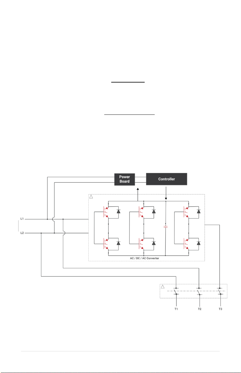
THEORY OF OPERATION ..........................................................................................1
BLOCK DIAGRAM........................................................................................................1
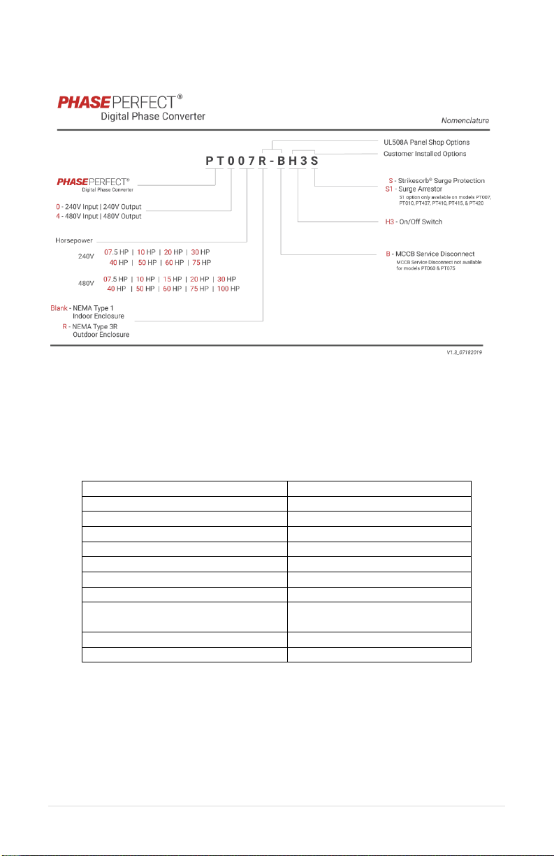
MODELS AND RATINGS ............................................................................................2
SPECIFICATIONS .......................................................................................................2
GENERAL SPECIFICATIONS .........................................................................................2
ELECTRICAL SPECIFICATIONS .....................................................................................3
MECHANICAL SPECIFICATIONS ....................................................................................4
DIMENSIONAL DRAWINGS ...........................................................................................5
INSTALLATION...........................................................................................................8
MOUNTING YOUR NEW PHASE PERFECT .....................................................................8
MOUNTING BRACKET INSTALLATION ............................................................................8
PROPER VENTILATION................................................................................................8
SERVICE ENTRANCE EQUIPMENT ................................................................................8
SOURCE BRANCH CIRCUIT PROTECTION......................................................................8
GROUNDING..............................................................................................................9
WIRE SIZING ...........................................................................................................11
CONNECTING THE LOAD ...........................................................................................11
CONNECTING TO FIELD WIRING TERMINALS...............................................................14
ROUTING POWER CABLES ........................................................................................15
ON/OFF CONTROL WIRING......................................................................................16
OPERATION..............................................................................................................17
LCD STATUS SCREEN..............................................................................................17
DIP SWITCH SETTINGS ...........................................................................................18
AUXINPUTS BYPASS...............................................................................................18
VFD MODE .............................................................................................................18
FAULTS WITH AUTO-RESTART...................................................................................19
FAULTS:MANUAL RESTART ......................................................................................20
FAULT LOG..............................................................................................................20
TROUBLESHOOTING TIPS......................................................................................21
ROUTINE INSPECTION AND MAINTENANCE.........................................................22
LINE FILTER CAPACITORS.........................................................................................22
FUSES ....................................................................................................................24
MOTOR STARTING/OVERLOAD CAPABILITIES ....................................................25
DEFINITIONS & ABBREVIATIONS...........................................................................27

1 | Page
V1.0
THEORY OF OPERATION
L1 and L2 of the single-phase input pass directly through the phase converter to provide
two legs of the three-phase output. The input module charges a DC bus from the input
lines. The output module uses power from the DC bus to generate the third leg of the three
phase output. The third leg is generated to limit voltage unbalance between the three legs
to ≤2%. Voltage unbalance is calculated according to the NEMA MG1 standard.
Where
Block Diagram
The diagram in Figure 1 illustrates the basic design schematic of the Phase Perfect.
Figure 1 –Phase Perfect Design Schematic

2 | Page
V1.0
MODELS AND RATINGS
Figure 2 –Phase Perfect Nomenclature
SPECIFICATIONS
General Specifications
Table 1: Common Specifications
Output Voltage
Appx. equal to input voltage
Output Voltage Unbalance
≤2%
Operating Temperature Range
-10°C (14°F) to 50°C (122°F)
Storage Temperature
-20°C (-4°F) to 60°C (140°F)
Efficiency
98.7%
Short Circuit Withstand Rating
10kA
Noise
75 dBA w/ fan running
50 dBA w/o fan running
Start Delay on Power Up
2 sec

3 | Page
V1.0
Electrical Specifications
Table 2 –240 V Models –Base Models and Ratings
Model
Power
(HP)
Output
(kVA)
Max Steady
State Output
Current (AAC)
Input
Voltage
Range
(VAC)
Max AC
Input
Current,
Typical (A)
Standby
Power/Energy,
Typical
(W/BTU/hr)
Preliminary
Full Load
Energy
Loss-
Typical
(BTU/hr)
PT007
7.5
10.8
26
187-260
45
70/239
479
PT010
10
14.9
36
62
74/252
661
PT020
20
26.6
64
111
80/273
1180
PT030
30
39.5
95
165
175/597
1752
PT040
40
54.0
130
225
190/648
2395
PT050
50
68.6
165
286
235/802
3043
PT060
60
78.9
190
329
260/887
3500
PT075
75
99.8
240
416
300/1024
4427
Table 3 –480 V Models - Base Models and Ratings
Model
Power
(HP)
Output
(kVA)
Max Steady
State Output
Current (AAC)
Input
Voltage
Range
(VAC)
Maximum
AC Input
Current,
Typical (A)
Standby
Power/Energy,
Typical
(W/BTU/hr)
Preliminary
Full Load
Energy
Loss-
Typical
(BTU/hr)
PT407
7.5
10.8
13
440-520
22
52/177
479
PT410
10
14.9
18
32
68/232
661
PT415
15
22.4
27
47
71/242
994
PT420
20
26.6
32
55
74/252
1180
PT430
30
38.2
46
80
87/297
1694
PT440
40
50.7
61
105
180/614
2249
PT450
50
64
77
134
190/648
2839
PT460
60
75.7
91
157
220/751
3358
PT475
75
90
107
185
270/921
3992
PT4100
100
118
142
246
300/1024
5239

4 | Page
V1.0
Mechanical Specifications
Table 4 –240 V Models –Enclosure Options & Specifications
Models
PT007
PT010
PT020
PT030
PT040
PT050
PT060
PT075
Options
NEMA 1 or 3R
Dimensions
Indoor: NEMA 1
(H x W x D)*
36 15/16” x 25 3/8” x 17 1/16”
44 15/16” x 25 13/16” x 19”
Dimensions
Outdoor: NEMA 3R
(H x W x D)*
37 7/16” x 25 3/8” x 19 5/16”
46 1/8” x 25 13/16” x 20 1/8”
Weight (lbs)
Preliminary
102
104
134
264
284
294
285
288
*Note: Dimensions are maximum measurements including mounting hardware and optional
MCCB handle. Weights include MCCB, except for PT060 and PT075
Table 5 –480V Models - Enclosure Options & Specifications
Models
PT407
PT410
PT415
PT420
PT430
PT440
PT450
PT460
PT475
PT4100
Options
NEMA 1 or 3R
Indoor:
NEMA 1
(HxWxD)
31 3/8” x 17 3/16” x 15 1/16”
36 15/16”x
25 3/8”x
17 1/16”
44 15/16” x 25 13/16” x 19”
Outdoor:
NEMA 3R
(HxWxD)
31 3/8” x 22 7/16” x 15 1/16”
37 7/16” x
25 3/8” x
19 5/16”
46 1/8” x 25 13/16” x 20 1/8”
Weight
(lbs)
Preliminary
62
64
68
74
141
286
287
298
304
334
*Note: Dimensions are maximum measurements including mounting hardware and optional
MCCB handle. Weights include MCCB

5 | Page
V1.0
Dimensional Drawings
Figure 3 –PT Small Frame Dimensions

6 | Page
V1.0
Figure 4 –PT Medium Frame Dimensions

7 | Page
V1.0
Figure 5 –PT Large Frame Dimensions

8 | Page
V1.0
INSTALLATION
Mounting Your New Phase Perfect
Proper installation of the unit is important to the performance and normal operating life of
the unit. The unit should be installed in a location free from:
Corrosive gases or liquids
Excessive vibration
Airborne metallic particles
Mount the unit to a solid, non-flammable surface capable of bearing the weight using the
mounting brackets provided with the unit. Weights for each model can be found in Table 4
and Table 5.
Mounting Bracket Installation
For shipping purposes, mounting brackets may be installed upside down. If the mounting
brackets are not installed in an upright position, remove the mounting screws and turn to an
upright position, then fasten the screws tightly.
Proper Ventilation
In order to maintain air circulation for adequate cooling, minimum clearance around the unit
must be maintained. Allow six inches on each side and top, and 18 inches below.
Ensure air intake and exhaust openings are not obstructed. If the unit is mounted in a small
room, cabinet, or building, ensure there is adequate ventilation to provide sufficient cooling
for the unit.
Service Entrance Equipment
The Phase Perfect phase converters are suitable for use as service equipment when the
molded case circuit breaker (MCCB)/disconnect, service ground conductor terminal and
grounding electrode conductor are factory installed and the converter is labeled “Suitable
for use as Service Equipment.” Consult local electrical code for installation guidance.
Source Branch Circuit Protection
If a circuit breaker is not factory installed, branch circuit protection must be installed in the
circuit sourcing the phase converter. See Table 7 for recommended circuit breaker sizing.
Fuses may be used for circuit protection, consult local electrical code for proper sizing.
Installation of a disconnection means within sight of the phase converter is recommended.

9 | Page
V1.0
Grounding
Properly ground the phase converter according to local electrical code.
Connect the ground lug to the branch circuit or service ground conductor.
Ground the phase converter with an adequately sized conductor according to
local electrical code.
Table 6 Ground Wire Specifications
Torque specifications based on solid to semi-rigid stranded copper wire. See terminal
markings for additional wire size and torque information.
Wire Range
(AWG)
Min Wire Size w/specified
Breaker
Models
Min
Max
Breaker
(A)
Wire
AWG
Torque
(in-lb)
PT007
14
2
60
10
40
PT010
14
2
80
8
40
PT020
14
2
150
6
40
PT030
14
2
200
6
40
PT040
14
2
250
4
50
PT050
14
2/0
400
3
50
PT060
14
2/0
500
2
50
PT075
14
2/0
600
1
50
PT407
14
2
30
10
40
PT410
14
2
40
10
40
PT415
14
2
60
10
40
PT420
14
2
70
8
40
PT430
14
2
100
8
40
PT440
14
2
150
6
40
PT450
14
2
175
6
40
PT460
14
2
200
6
40
PT475
14
2
250
4
50
PT4100
14
2/0
400
3
50

10 | Page
V1.0
Table 7 Input Wiring (75°C Wire)
Wire size recommendations based on 600VAC, 75°C rated copper wire. Assuming 86°F
(30°C) ambient and no more than 3 current carrying conductors in raceway, cable or earth
(directly buried).
Input Wiring Recommendations
Heavy Duty1
Light Duty2
Circuit
Breaker
Wire Gauge
Torque
in-lb
Circuit
Breaker
Wire
Gauge
PT007
60
6 AWG
120
50
8 AWG
PT010
80
4 AWG
120
60
6 AWG
PT020
150
1/0 AWG
120
125
1 AWG
PT030
200
3/0 AWG
275
200
3/0 AWG
PT040
250
250 kcmil
275
250
250 kcmil
PT050
400
2x3/0
375
300
350 kcmil
PT060
500
2x250 kcmil
375
350
500 kcmil
PT075
600
2x350 kcmil
375
500
2x4/0 AWG
PT407
30
10 AWG
120
30
10 AWG
PT410
40
8 AWG
120
40
8 AWG
PT415
60
6 AWG
120
50
8 AWG
PT420
70
4 AWG
120
60
6 AWG
PT430
100
3 AWG
120
100
3 AWG
PT440
150
1/0 AWG
120
125
1 AWG
PT450
175
2/0 AWG
120
150
1/0 AWG
PT460
200
3/0 AWG
275
200
3/0 AWG
PT475
250
250 kcmil
275
250
250 kcmil
PT4100
400
2x3/0
375
300
350 kcmil
1
Heavy Duty: Single motor loads with heavier inertial loads that typically require class 10
overload.
2
Light Duty: Non motor loads, system not running near full load amps, motors that start
with little or no inertial load, motors started with a soft starter.
NOTE: PT060 & PT075 are not rated to start across the line motors at the full horsepower
rating.

11 | Page
V1.0
Table 8 Input Wiring (60°C Wire)
Wire size recommendations based on 600VAC, 60°C rated copper wire. Assuming 86°F
(30°C) ambient and no more than 3 current carrying conductors in raceway, cable or earth
(directly buried).
Input Wiring Recommendations (60°C rated wire)
Heavy Duty
Light Duty
240 V
Circuit
Breaker
(A)
Wire
Gauge
Torque in-lb
Circuit
Breaker
(A)
Wire
Gauge
PT007
60
4 AWG
120
50
8 AWG
PT010
80
3 AWG
120
60
6 AWG
PT407
30
10 AWG
120
30
10 AWG
PT410
40
8 AWG
120
40
8 AWG
PT415
60
4 AWG
120
50
6 AWG
PT420
70
4 AWG
120
60
4 AWG
PT430
100
1 AWG
120
100
1 AWG
Wire Sizing
Use Table 7to find minimum guidelines in properly sizing input and output conductors
according to local electrical code. The voltage drop from the supply to the converter should
be limited to 3% to ensure proper starting and operation of motor loads. Increase the wire
gauge to provide adequate voltage to the load. Ensure the wire gauge is suitable to the
terminal block.
Use the following formula to calculate line voltage drop.
Connecting the Load
Do not connect single phase loads to the manufactured leg, T3. This places unnecessary
load on the phase converter and may violate electrical code in some areas. Apply overload
and short circuit protection to protect load side conductors, motors and other attached
loads according to local electrical code. For some motor loads and wiring configurations
load side short circuit protection may not be required. Consult local electrical code for
guidance.

12 | Page
V1.0
Important Note:
If the connected load requires a wye configured power source with a neutral connection,
the load must be connected to the phase converter using a delta-wye isolation transformer.
Figure 6 –Delta Wye Wiring Diagram
Table 9 Input Power Terminal Specifications
Input Power Terminals: Allowed Wire Range & Minimum Torque
Model
PT007, PT010, PT020,
PT407, PT410, PT415,
PT420, PT430, PT440,
PT450
PT030, PT040, PT460,
PT475
PT050, PT060, PT075,
PT4100
Wire Size
Torque
Wire Size
Torque
Wire Size
Torque
2/0 –6 AWG
120 in-lb
350 kcmil-
6 AWG
275 in-lb
2x500 kcmil-
2x4 AWG
375 in-lb
8 AWG
40 in-lb
10 –14 AWG
35 in-lb
Table 10 Output Power Terminal Specifications
Output Power Terminals: Allowed Wire Range & Minimum Torque
Model
PT007, PT010, PT020, PT030, PT040,
PT407, PT410, PT415, PT420, PT430,
PT440, PT450, PT460, PT475, PT4100
PT050, PT060, PT075
Wire Size
Torque
Wire Size
Torque
2/0 –6 AWG
120 in-lb
350 kcmil –6 AWG
275 in-lb
8 AWG
40 in-lb
10 –14 AWG
35 in-lb

13 | Page
V1.0
Table 11 –Field Wiring Tools
Model
Line Side
Load Side
Model
Line Side
Load Side
PT007
3/16" Hex
3/16" Hex
PT407
3/16" Hex
3/16" Hex
PT010
PT410
PT020
PT415
PT030
PT420
PT040
5/16" Hex
PT430
PT050
PT440
PT060
3/8" Hex
5/16" Hex
PT450
PT075
PT460
5/16" Hex
PT475
PT4100
Table 12 Optional Circuit Breaker Wire Size and Torque
Models
Circuit Breaker
Family
Min
Max
Wire
Strip
Min Torque
(in-lb)
PT007
PT010
PT407
PT410
PT415
PT420
PT430
LS UTE100
14
10
0.7”
31.9
8
39.9
6
3
47.8
2
1
55.7
PT020
PT440
LS UTS150
14
1.01”
36.2
12
10
47.8
8
2/0
133.6
PT030
PT460
PT475
LS UTS250
1/0
2/0
1.27”
254.9
3/0
4/0
350.5
250
kcmil
300
kcmil
350.5
PT040
PT050
PT4100
LS UTS400
1/0
300
kcmil
1.76”
358.4
350
kcmil
600
kcmil
477.9

14 | Page
V1.0
Connecting to Field Wiring Terminals
Open the front door of the enclosure to gain access to the wiring panel.
See Figure 7 -Figure 9.
Figure 7 –PT Small Frame Field Wiring
Terminals
Figure 8 –PT Medium Frame Field Wiring
Terminals
Figure 9 –PT Large Frame Field Wiring Terminals
Table 13 –Power Terminal Descriptions
Terminal Name
Description
L1, L2
Single phase input power terminals
T1, T2, T3
3 Phase output power terminals, T3 is the “manufactured” leg.
GND
Earth ground
Small Frame Models:
PT407, PT410, PT415,
PT420
Medium Frame Models:
PT007, PT010, PT020,
PT430
Large Frame Models:
PT030, PT040, PT050,
PT060, PT075, PT440,
PT450, PT460, PT475,
PT4100
This manual suits for next models
16
Table of contents