4
Safety Instructions
WARNINGS
CAUTIONS
Before starting
to use
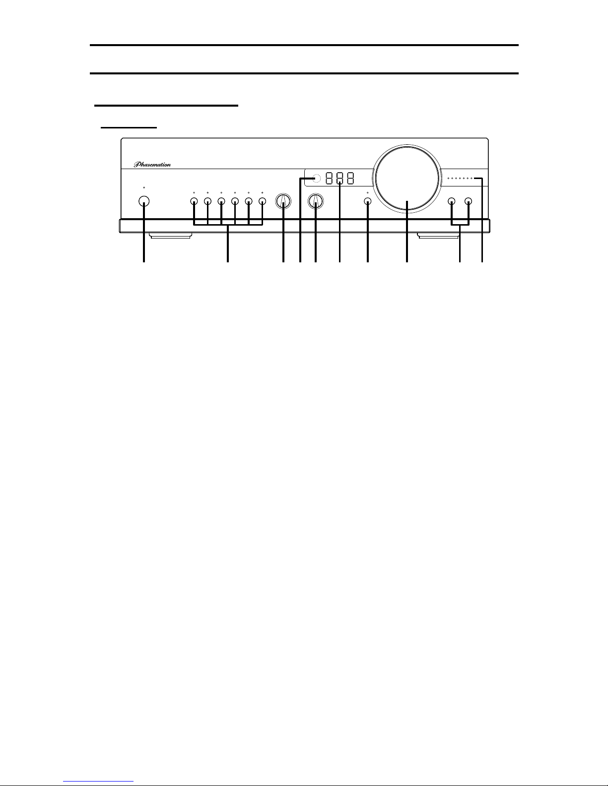
In this owner’s manual and on the product, various pictures are used
to show our customers how to use Phasemation CA-1000 safely and
properly in order to avoid the loss of customer’s assets and to protect
our customers from harm.
Do not use the
equipment being
broken.
Never remodel the
equipment.
Never install the
equipment near
water.
Never put an object
filled with water on
the equipment.
Never put an object
inside the equipment.
Cautions of
Installation
Places which are not
suitable for
installation
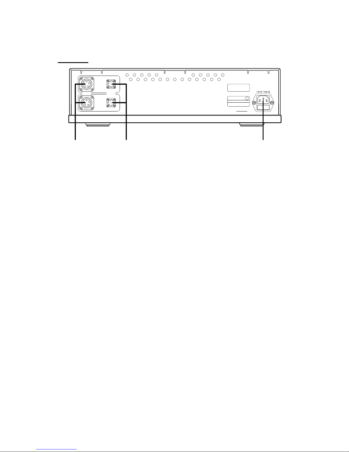
Connection
In case of using the equipment in an abnormal
state, such as seeing smoke, having strange
smell or hearing unusual sounds or noises, this
can result in a risk of fire or electric shock. If
such an abnormal state occurs, turn the power
switch off and endure to disconnect the AC plug
from the outlet. After no smoke is confirmed, ask
the dealer for the repair.
Do not disassemble the equipment or remodel
it. This can result in a risk of fire.
Do not use the equipment in the bathroom. This
can result in a risk of fire or electric shock.
The equipment is designed for using indoors.
Do not expose the equipment to water. This can
result in a risk of failures, fire and electric shock.
Do not put a vase, flower pot, glass or any
object filled with skin lotion, chemical substance
or water, or small metal objects on the
equipment. In case the liquids are spilled or the
small objects fall inside the equipment, this can
result in a risk of fire or electric shock.
If a foreign object has fallen inside the
equipment, turn the amplifier’s power switch off
and contact the dealer. To keep using the
equipment can result in a risk of fire or electric
shock.
Do not install the equipment in the humid or
dusty environment. This can result in a risk of
fire or electric shock.
When connecting with other audio equipments
or a television set, read the manual of the
equipment, turn the power switch off, and
connect according to the instructions.
Do not install the equipment on the unstable
tables or unstable places. In case the equipment
falls, it can result in a risk of injury of customers.
Pay attention to the wiring of the cord so that a
foot is not caught or the person can stumble or
the equipment can fall, which is so dangerous.
When moving the equipment, turn the power
switch off and endure to disconnect the power
plug from the outlet and remove the connecting
cord. The cord can be damaged and this can
result in a risk of fire and electric shock.