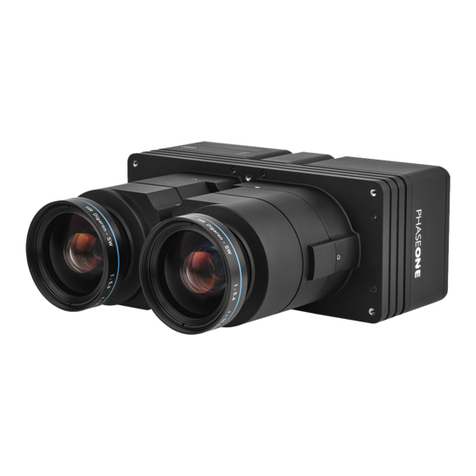
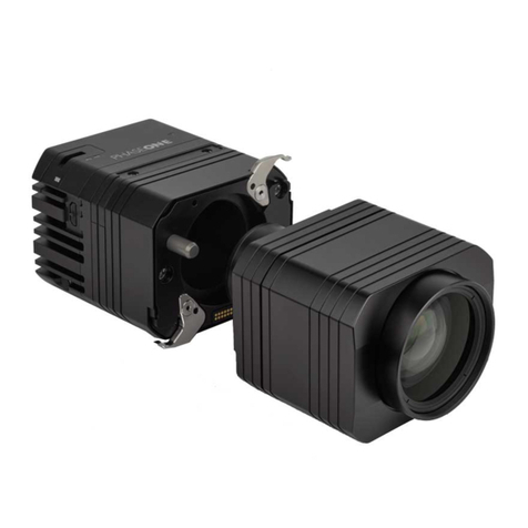
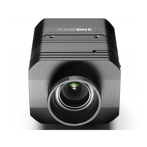
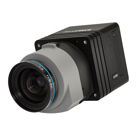
PhaseOne iXM-GS120 User manual

iXM-GS120
Operation Guide

iXM-GS120 Operation Guide
Page 2 of
32
Legal Notice
The company disclaims all liability and warranties in relation to this manual, including warranty of merchantability, fitness for
particular purpose and accuracy, and may amend it without further notice.
Trademarks
All trademarks or registered trademarks are the property of their respective owners.
Contact Support
You can contact Phase One Technical Support directly by creating a support case at
https://support.phaseone.com/
Visit https://geospatial.phaseone.com/ for additional information.
Copyright © 2022 Phase One. All Rights Reserved.
iXM-GS120 Operation Guide
Doc No. 80107000 Rev 1.0.0 07/11/2022

iXM-GS120 Operation Guide
Table of Contents
Page 3 of
32
Table of Contents
1Introduction 5
1.1 Scope ................................................................................................................................................................................. 5
1.2 Applicable Documents ....................................................................................................................................................... 5
1.3 List of Terms and Abbreviations ........................................................................................................................................ 5
2iXM-GS120 Overview ..................................................................................................................................................................... 6
3Camera Features ............................................................................................................................................................................7
3.1 Exposure Sequence............................................................................................................................................................7
3.2 Black Reference ................................................................................................................................................................. 8
3.2.1 Understanding Black Reference .........................................................................................................................8
3.2.2 Hardware Activation of Black Reference............................................................................................................8
3.2.3 Software Activation of Black Reference .............................................................................................................9
3.3 Electrical Interfaces.......................................................................................................................................................... 10
4Cable Specifications......................................................................................................................................................................11
4.1 Power Cable..................................................................................................................................................................... 11
4.2 Control Cable ................................................................................................................................................................... 12
5Unboxing the Camera................................................................................................................................................................... 14
6Preparing the Camera .................................................................................................................................................................. 15
6.1 Mounting an RSM Lens .................................................................................................................................................... 15
6.2 Dismounting a RSM Lens .................................................................................................................................................17
6.3 Mounting a RS Lens ......................................................................................................................................................... 17
6.4 Dismounting a RS Lens.....................................................................................................................................................18
7Connecting the Camera................................................................................................................................................................19
7.1 Attaching the Camera (iXM-GS120) to a Pod...................................................................................................................19
7.2 Connecting a Control Cable ............................................................................................................................................. 19
7.3 Connecting the Power Cable............................................................................................................................................19
7.4 Connecting a USB Cable................................................................................................................................................... 20
7.5 Connecting Cables for Multiple Camera Configuration ...................................................................................................20
7.6 Connecting the HDMI Cable.............................................................................................................................................21
8Configuring Auto-Exposure Mode................................................................................................................................................ 22
9Storing Images.............................................................................................................................................................................. 25
9.1 Using Memory Cards........................................................................................................................................................25
9.1.1 Inserting and Ejecting a Memory Card .............................................................................................................25
9.1.2 Formatting a Memory Card..............................................................................................................................26
10 Live Video Display ........................................................................................................................................................................ 27
10.1 Using Live View with iX Capture ...................................................................................................................................... 27

iXM-GS120 Operation Guide
Table of Contents
Page 4 of
32
10.2 Setting HDMI Display ....................................................................................................................................................... 27
11 Miscellaneous Camera Settings ...................................................................................................................................................28
11.1 Setting shutter, ISO and Aperture....................................................................................................................................28
11.2 Setting Camera Date & Time ...........................................................................................................................................28
11.3 Setting Image Orientation................................................................................................................................................28
11.4 Setting GPS Time Mode & Receiver .................................................................................................................................28
11.5 Setting When Low Power Mode is Activated...................................................................................................................29
11.6 Restoring Default Camera Values .................................................................................................................................... 29
12 Firmware 30
12.1 Installing the Firmware Updater ......................................................................................................................................30
12.2 Updating the Firmware....................................................................................................................................................30
12.3 Checking Firmware Version ............................................................................................................................................. 31
12.4 Restoring Firmware to Factory Version ...........................................................................................................................31
13 Interpreting the Camera LEDs ...................................................................................................................................................... 32
13.1 Temperature Warning ..................................................................................................................................................... 32

iXM-GS120 Operation Guide
1. Introduction
Page 5 of
32
1Introduction
1.1 Scope
This guide describes how to operate the iXM-GS120 as follows:
•Section 2 - iXM-GS120 Overview
•Section 3 - Camera Features
•Section 4 - Cable Specifications
•Section 5 - Unboxing the Camera
•Section 6 - Preparing the Camera
•Section 7 - Connecting the Camera
•Section 8 - Configuring Auto-Exposure
•Section 9 - Storing Images
•Section 10 - Live Video Display
•Section 11 - Miscellaneous Camera Settings
•Section 12 - Firmware
•Section 13 - Interpreting the Camera LEDs
1.2 Applicable Documents
Item
Manual
iX Capture
iX Capture User Guide
1.3 List of Terms and Abbreviations
Term/Abbreviation
Description
FMS
Flight Management System.
HDMI
High-Definition Multimedia Interface connector for monitors.
XQD card
Format for flash memory cards.
CFexpress
Format for flash memory cards.

iXM-GS120 Operation Guide
2. iXM-GS120 Overview
Page 6 of
32
2iXM-GS120 Overview
The iXM-GS120 is a wide area high resolution camera with high sensitivity, low noise, and minimal integration time for diverse
demanding applications.
The iXM-GS120’s global shutter technology enables record-breaking short exposures without the need for a mechanical shutter.
The camera can be used with various Phase One’s lens series featuring different focal length options, ranging from 35mm to
180mm.
The following figures show the location of iXM-GS120 parts.
1. Pod mounting threaded holes (four)
2. Lens secure screws (four)
3. Memory card slot cover
4. Memory card slot cover screw
5. Storage LED
6. Operation LED
7. USB 3.1 port cover screw
8. USB 3.1 port cover
9. Left LEMO port (data)
10. Center LEMO port (data)
11. Right LEMO port (power)
12. Power LED
13. Ethernet port cover screw
14. Ethernet port cover
15. HDMI port cover
16. HDMI port cover screw

iXM-GS120 Operation Guide
3. Camera Features
Page 7 of
32
3Camera Features
3.1 Exposure Sequence
The following figure and tables describe the signals and hardware pulses that control the exposure sequence.
Exposure Sequence
Exposure Sequence Signals
Signal
Description
Trigger In
The FMS signals the camera to capture an image.
System Ready
Camera ready/busy signal.
Mid-Exposure Pulse
Indicates the midpoint of the exposure time.
Black Reference/Wakeup Control
Dual-purpose signal.
Hardware Pulses and Delay Parameter Signals
Sequence Step Shutter = ES
Shutter = LS
Normal Mode
T1
Trigger IN – SysRdy (Low)
2.5 msec 2.5 msec
T2
Trigger IN – Mid Exposure
~20 msec +
0.5*Exposure Time
~25 msec +
0.5*Exposure Time
T3
Mid Exposure Width
0.5*Exposure Time 0.5*Exposure Time
T4
Trigger IN – SysRdy (High)
100 msec 122 msec
T5
Wakeup pulse (minimum) 1 msec 1 msec
T6
Wakeup pulse – Trigger IN (minimum)
350 msec 350 msec

iXM-GS120 Operation Guide
3. Camera Features
Page 8 of
32
3.2 Black Reference
3.2.1 Understanding Black Reference
A black reference is the process of reading the sensor output during an exposure without the sensor being exposed to light. This
data is written to the camera and subtracted from regular captures to filter out sensor noise.
Updating the black reference data whenever possible enhances the image quality, particularly when shooting in conditions where
the camera temperature fluctuates. If the exposure time varies considerably, the black calibration reference data should be
updated.
To ensure exposure accuracy, a black reference capture should be made before starting your first flight line, or if exposure settings
or ISO have been changed. This is best done before starting a new flight line, when images are not being captured.
3.2.2 Hardware Activation of Black Reference
If you are building your own hardware control box, you can update the black reference data in the camera. The black reference
control signal should be kept low while an image capture cycle is initiated. The signal must remain low for the full capture cycle.
This makes it possible to create a black reference whenever it is convenient (such as when turning an aircraft around or between
flight lines). When the force black signal is kept high, the camera uses the last updated black reference data.
Black reference timing is shown in the following figure.
Note
in some cases, enabling low power mode (see Section 11.5 Setting When Low Power Mode) can cause slowness in capture rate
when the image capture rate is slower than the low power mode timing. If, for example, the capture rate is scheduled at 15
seconds and the low power mode is set at 10 seconds, each capture will be delayed by up to 350mS. As a result, the capture
rate will be 15.35 S/F instead of 15 S/F in order to allow the camera to exit low power mode. If the capture rate is crucial,
disable low power mode or use hardware wakeup signal.
Note
Black reference is performed automatically with the first shot after switching the camera on.

iXM-GS120 Operation Guide
3. Camera Features
Page 9 of
32
3.2.3 Software Activation of Black Reference
The iXM-GS120 camera can perform a black reference sequence through iX Capture, the Phase One SDK, or the Flight Management
System.
The following table describes the black reference mode to use for your capture flow.
Black Reference Mode
Description
Prerecorded
This mode uses a prerecorded black reference created during iXM-GS120 production. As a
result, there is no delay in capture flow and the black reference is used for each capture.
Once
This mode takes a black reference one time only. This mode is usually selected for normal
captures in where there are no large changes to exposure time, ISO, or temperature.
Phase One recommends that you initiate a new black reference sequence whenever
possible (for example, during flight while turning the aircraft).
Always
This mode takes a new black reference for every capture.
Note
This slows the capture cycle (approximately twice as slow) but does provide an
accurate, custom black reference for each capture.
On Change
The camera uses an internal algorithm to decide when a new black reference is required,
based on specific values of exposure, ISO, or large changes in temperature.

iXM-GS120 Operation Guide
3. Camera Features
Page 10 of
32
3.3 Electrical Interfaces
The following figure shows the four signals that control the iXM-GS120 camera:
Schematic Drawings
Trigger in
Triggers the
iXM-GS120 camera
for new capture cycle.
Black reference
Triggers the
iXM-GS120 camera
for a black
reference
Mid
-exposure pulse
Indicates midpoint of the
exposure time.
Camera ready/busy signal

iXM-GS120 Operation Guide
4. Cable Specifications
Page 11 of
32
4Cable Specifications
4.1 Power Cable
The power cable open end is connected to the aircraft’s power bus, and the LEMO connector end is connected to the camera right
LEMO (power) port.
Figure 1. Power Cable Plug
Figure 2: Power Socket Pinouts
1. Connect the power cable using the information in the following table:
Power Cable Description
Connector Pin Color Name Description Direction Level Notes
1
White or yellow
DC In +
Provides positive power
Input
12 - 30 V DC
Provides up to
20 W
2
Black
DC In -
(Common)
Input

iXM-GS120 Operation Guide
4. Cable Specifications
Page 12 of
32
4.2 Control Cable
The control cable open end is connected to your system through nine (28 AWG) wires, and the LEMO connector end is connected
to the camera center or left LEMO (data) port, depending on your system configuration.
The following figures and table show the cable pinout and signals.
Control Cable Plug Pinout
Camera Socket Pinout
Control Cable Signals
Pin Color Name Description Direction
Parameter Voltage
Levels
(see next table)
Notes
1
Orange
Reserved
Reserved
Reserved
Reserved
Reserved
2
Green
System Ready
iXM-GS120 ready for
next capture.
Out
VOH, min = 4.0V
(Io = -10uA)
VOL, max = 0.8V
(Io = 4mA)
5 V level pull up resistor
47.5K Ohms to +5 V
3
Red
Black Reference/
Wakeup Control
Indicates a black
reference sequence is
required.
In
VIH, min = 2.4V
VIL, max = 0.8V
tiF, tiR < 1uSec
Isolated. Active low. For black
reference, see Section 3.2 Black
Reference

iXM-GS120 Operation Guide
4. Cable Specifications
Page 13 of
32
Parameters Description
Parameter
Setting
VIL
Maximum voltage level that is interpreted as 0 by an input.
VIH
Minimum voltage level that is interpreted as 1 by an input.
VOL
Guaranteed maximum voltage level that appears on output set to 0.
VOH
Guaranteed minimum voltage level that appears on output set to 1.
VIT+
Input threshold voltage when the input voltage is rising.
VIT-
Input threshold voltage when the input voltage is falling.
VIL
Maximum voltage level that is interpreted as 0 by an input.
VIH
Minimum voltage level that is interpreted as 1 by an input.
VOL
Guaranteed maximum voltage level that appears on output set to 0.
Pin Color Name Description Direction
Parameter Voltage
Levels
(see next table)
Notes
Signal the camera to
wakeup from low power
mode.
Understanding Black Reference.
For low power mode control, see
Section 3.1 Exposure Sequence.
4
Purple
Trigger In
Trigger the iXM-GS120
for new capture cycle.
In
VIH, min = 2.4V
VIL, max = 0.8V
tiF, tiR < 1uSec
Active low (for manual triggering,
activate by short to common
signal, otherwise leave floating).
5
Blue
RS-232 RX
External system can
send specific
information to the iXM-
GS120.
In
RS-232 input level
+/- 15V
(VIT+ max=2.4V)
(VIT- min=0.8V)
RS232 voltage level isolated. For
baud rate and additional
information, see the Phase One
Camera and GNSS IMU Installation
Guide.
6
Yellow
RS-232 TX
iXM-GS120 can send
specific information to
external system.
Out
VOH at RL=3 kΩ to
GND + 5.4V
VOL at RL=3 kΩ to
GND - 5.4V
7
White
Mid-Exposure
Pulse
Midpoint of the
exposure time.
Out
VOH min = 4.0V (Io=
-4mA) VOL max =
0.8V (Io= 4mA)
5 V level.
8
Gray
Reserved
Reserved
In
Short to pin 9 (mandatory).
9
Black
Common
Common

iXM-GS120 Operation Guide
5. Unboxing the Camera
Page 14 of
32
5Unboxing the Camera
Verify that all parts were supplied according to the specific packing list for your system.

iXM-GS120 Operation Guide
6. Preparing the Camera
Page 15 of
32
6Preparing the Camera
6.1 Mounting an RSM Lens
To mount a lens on a camera:
1. Place the camera interface with the sensor facing up and the camera contacts (solid blue) closest to you.
Camera Interface
2. Hold the RSM lens so that the lens contacts (solid green) are aligned with the camera contacts (solid blue).
RSM Lens
3. Place the lens groove on the camera ridge (opening-to-opening).
Note
•Before mounting or dismounting a lens, verify that the power cable is not attached to the camera.
•Mount/dismount lenses only in a clean environment.
•Place a soft cloth on the table to avoid scratching the camera.
•Place a lens cap on the lens.
Lens groove
Lens contacts
Camera ridge
Camera contacts

iXM-GS120 Operation Guide
6. Preparing the Camera
Page 16 of
32
4. With the openings touching, lower the lens contacts to the camera contacts.
5. Hold the lens with both hands and press it firmly down onto the camera, so that the O-Ring seal is pressed inside.
6. Use a 2 mm hex key to tighten the 4 screws on the camera interface to a torque of 50 cNm.
O-Ring

iXM-GS120 Operation Guide
6. Preparing the Camera
Page 17 of
32
6.2 Dismounting a RSM Lens
To dismount a lens from an iXM:
1. Use a 2 mm hex key to unscrew the four screws on the iXM camera.
2. Hold the lens and gently pull up at an angle.
6.3 Mounting a RS Lens
To mount an RS lens on the camera:
1. Remove the rear lens cap.
2. Hold the RS lens so that the lens contacts strip is above the RS adaptor contacts.
3. Slowly lower the lens opening onto the RS adaptor opening (opening -to-opening).
4. Use a 2 mm hex key to secure the lens assembly onto the RS adaptor by gently tightening each of the three locking screws.
5. Tighten the 3 locking screws a second time using a torque of 50 cNm.

iXM-GS120 Operation Guide
6. Preparing the Camera
Page 18 of
32
6.4 Dismounting a RS Lens
To dismount the lens from an iXM-RS:
1. Use a 2 mm hex key to unscrew the three lens screws.
2. Pull the lens assembly away from the camera.
3. Place a rear cap on the lens.
Note
The screws remain attached to the camera.

iXM-GS120 Operation Guide
7. Connecting the Camera
Page 19 of
32
7Connecting the Camera
7.1 Attaching the Camera (iXM-GS120) to a Pod
1. Attach the iXM-GS120 camera to a pod using four M4 screws.
7.2 Connecting a Control Cable
1. Connect the control cable LEMO connector to camera left LEMO (data) port (near the USB port).
2. Connect the other end of the control cable to your external device.
7.3 Connecting the Power Cable
To connect the camera to the aircraft power bus:
1. Connect the power cable LEMO connector to camera power port.
2. Connect the other end of the power cable to the aircraft power bus.
Caution
The iXM-GS120 camera must be powered by a limited fused power source only, up to 2A single fault condition.
Note
Do not insert screws deeper than 6 mm into the threaded holes on the front of the camera.
Note
•The two data ports (left and center LEMO ports) are not interchangeable.
•If the camera is being used with a Phase One system, use a control cable with LEMO connectors at both ends, and connect
the other end to the iX Controller i/O port.

iXM-GS120 Operation Guide
7. Connecting the Camera
Page 20 of
32
7.4 Connecting a USB Cable
To connect a USB 3.1 cable to a PC:
1. Using a 2 mm hex key, remove the screw securing the USB 3.1 port cover.
2. Remove the cover and store it.
3. Connect the USB 3.1 cable connector to the camera USB port.
4. Tighten both locking screws on the USB connector to secure it to the port using a torque of 25 cNm.
7.5 Connecting Cables for Multiple Camera Configuration
You can connect multiple iXM-GS120 cameras through a daisy-chain to capture images simultaneously. The first camera in the
daisy-chain is triggered through the control cable.
1. On the first camera in the daisy chain, connect a control cable LEMO connector to the left LEMO port.
2. Connect the other end of the control cable to your external device.
3. Connect one end of the Multi-Sync cable to the center LEMO port.
4. Connect the other end of the Multi-Sync cable to the left LEMO port of the next camera.
5. Repeat for any additional cameras.
6. On the last camera in the daisy chain, connect a control cable LEMO connector to the center LEMO port.
7. Connect the other end of the control cable to your flight management system or other device.
Note
•For a multiple camera setup, do not use the software trigger or software black reference from iX Capture. Use hardware
signals only.
•When creating a daisy-chain between iXM-GS120 and iXU-RS/iXU cameras, each camera can be configured in any position
required. However, you must disable the low power mode for the iXM-GS120 cameras.
Table of contents
Other PhaseOne Digital Camera manuals

PhaseOne
PhaseOne iXH User manual

PhaseOne
PhaseOne 645DF User manual

PhaseOne
PhaseOne 645 User manual

PhaseOne
PhaseOne XF User manual

PhaseOne
PhaseOne iXU-RS User manual

PhaseOne
PhaseOne Studiokit User manual

PhaseOne
PhaseOne 645 AF User manual

PhaseOne
PhaseOne iXR User manual

PhaseOne
PhaseOne iXU-RS 1900 User manual

PhaseOne
PhaseOne 645DF User manual

PhaseOne
PhaseOne P 65+ User manual

PhaseOne
PhaseOne 645DF User manual

PhaseOne
PhaseOne H 10 C645 User manual

PhaseOne
PhaseOne DJI M600 User manual

PhaseOne
PhaseOne 645DF User manual

PhaseOne
PhaseOne 645DF User manual

PhaseOne
PhaseOne XF User manual

PhaseOne
PhaseOne iXG User manual

PhaseOne
PhaseOne iXG Manual

PhaseOne
PhaseOne P 25 User manual