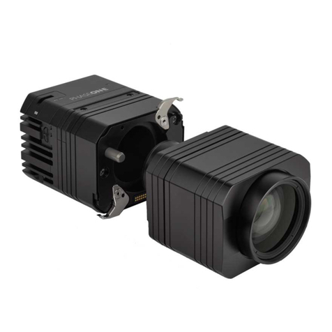
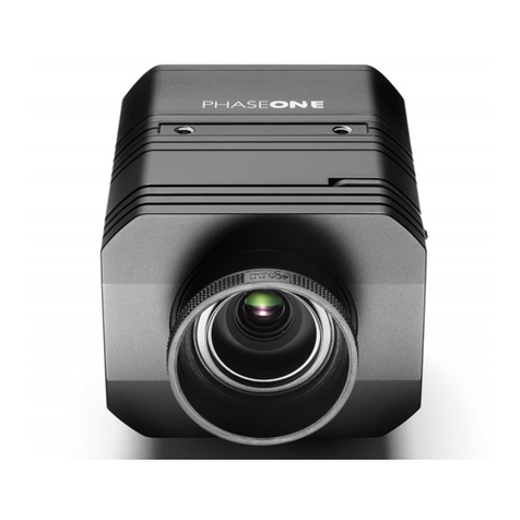
PhaseOne iXU-RS 1900 User manual

1
Phase One
iXU-RS 1900
Aerial Camera System
Installation Guide

32
Contents
1. What’s in the Box? ................................................................................... 5
Optional Accessories.............................................................................. 5
2. Overview.......................................................................................................6
iXU-RS 1900 Camera System.............................................................6
3. Preflight Planning..................................................................................... 8
Exposure Sequence ................................................................................9
Understanding the Exposure Sequence.......................................9
Wiring a Control Cable........................................................................ 10
Wiring a Control Cable for an iXU-RS1900 ................................12
Understanding Black Reference ......................................................12
Black Reference Sequence.................................................................13
Wiring the Power Cable...................................................................... 14
Electrical Interfaces................................................................................16
5. Connecting a Camera ...........................................................................18
Attaching the Camera to a Pod.......................................................18
Connecting a Control Cable ..............................................................18
Connecting the Power Cable ............................................................19
Connecting Control Cables to Devices ..................................... 20
Connecting Cables for Multiple Camera Configuration ......22
Connecting a USB 3.0 Cable to an Onboard Computer.....24
Connecting a GNSS/IMU................................................................... 26
9. Firmware ....................................................................................................28
Checking the Firmware Version......................................................28
About the Phase One Firmware Updater Application........ 29
Installing the Firmware Updater Application .......................... 29
Updating the Firmware...................................................................... 30
Restoring the Firmware .....................................................................33
This guide is designed to assist you
with the installation of your new
Phase One iXU-RS 1900
As new features are introduced through firmware
updates, a downloadable version
is now available in the Downloads section of
http://industrial.phaseone.com/downloads-guides.aspx

5
1. What’s in the Box?
Optional Accessories
• iXU RA control cable, 3 m (70360)
• iXU RA multi-sync cable, 1 m (70362)
• iXU to iXA multi-sync cable, 1 m (70341)
• USB3 Shield Cable for iXU (1m) (73126)
• USB3 Shield Cable for iXU (3m) (73128)
• Phase One iXU-RS 1900 camera
• Two Rodenstock RS-90mm Lenses
• Two sets of 24 V DC power supply with
international outlet adapters
• Two iXU RA power cables, 2 m
• iXU RA control cable, 2 m
• iXU multi-sync cable 30 cm
• Two USB3 Shield cable, 2 m
• 2 mm hex screwdriver
• Microfiber cloth
• Sensor cleaning kit
• USB drive with documentation
• iXU-RS 1900 Installation guide
• Warranty certificate
• Suitcase for iXU-RS 1900 camera

76
3. Setup button
4. Navigation Button
5. Power terminal
6. Data terminal A
7. Data terminal B
8. USB 3.0 port screw
9. USB 3.0 port cover
10. Play button
11. Menu button
2. Overview
iXU-RS 1900 Camera System
1. Pod mounting threaded holes (6)
2. Lens secure cams (6)
11
1
1
2
2
1
9
5
4
6
8
7
10
39
54
6
8
7
10
3
11

98
Exposure Sequence
To learn more about the capabilities of the iXU-RS 1900 camera,
consult the http://industrial.phaseone.com/Aerial_Systems.aspx
website and the document files saved on the USB drive
provided with the camera.
Understanding the Exposure Sequence
There are three signals that are used to communicate with
and control the iXU-RS 1900 exposure sequence:
• Trigger in: The Flight Management System (FMS) signals
the iXU-RS 1900 to take an image.
• System ready: Camera ready/busy signal.
• Mid-exposure pulse: A signal indicates the midpoint of the
exposure time.
Trigger In
System
Ready
Mid-
exposure
Pulse
T4
T1
T2 T3
Figure 1: Exposure Sequence
Table 1 – Exposure sequence
3. Preflight Planning
Typical Values RS lenses
T1
Trigger IN – SysRdy (Low)
2 mSec
T2
Trigger IN – Mid Exposure
~20 mSec + 1/2 Exp.
Time
T3
Mid Exposure Width
1/2 Exp. Time + 1.1 mSec
T4 (iXU 1900)
Trigger IN – SysRdy (High)
600 mSec

1110
Table 2 – Camera Control Cable Description
Pin Color Name Description Direction Level Notes
1Orange Reserved Reserved Reserved Reserved Reserved
2 Green System
Ready
iXU-RS 1900 system
ready for next capture
Out VOH, min = 4.0 V (Io = -10uA)
VOL, max = 0.8 V (Io = 4mA)
Isolated
5 Volt Level
Pull up resistor 100K Ohms
to +5 V
3Red Black
Reference
Control
Indicates a black
reference sequence is
required
In VIH, min = 2.4 V
VIL, max = 0.8 V
tiF, tiR < 1uSec
Isolated, active low
See 'Understanding Black
Reference' on page 12
4 Purple Trigger In Trigger the iXU-RS
1900 for new capture
cycle
In VIH, min = 2.4 V
VIL, max = 0.8 V
tiF, tiR < 1uSec
Isolated, active low
For manual triggering,
activate by short to common
signal, otherwise leave floating.
5 Blue RS232 RX External system
can send specific
information to
iXU-RS 1900 system
In RS232 input level +/- 15 V
(VIT+ max=2.4 V
VIT-min=0.8 V)
RS232 Voltage Level Isolated
For baud rate and additional
information, see the Phase
One GNSS User Guide*
6 Yellow RS232 TX iXU-RS 1900 system can
send specific information
to external system
Out VOH at RL=3 kΩ to GND +5.4
V
VOL at RL=3 kΩ to GND –5.4
V
7 White Mid-exposure
pulse
Midpoint of the
exposure time
Out VOH, min = 4.0 V (Io= -4mA)
VOL, max = 0.8 V (Io= 4mA)
Isolated
5 Volt Level
8Gray Reserved Reserved In Short to pin 9**
9 Black Common Common
VIL — maximum voltage level that is interpreted as a ‘0’ by a input.
VIH — minimum voltage level that is interpreted as a ‘1’ by a input.
VOL — guaranteed maximum voltage level that appears on
output set to ‘0’.
VOH — guaranteed minimum voltage level that appears on
output set to ‘1’.
VIT+ — input threshold voltage when the input voltage is rising.
VIT– — input threshold voltage when the input voltage is falling
Wiring a Control Cable
*A comprehensive guide to connecting Phase One aerial
cameras with a GNSS receiver is available for download from
http://industrial.phaseone.com/downloads-guides.aspx
**This connection is mandatory.

1312
Black Reference Sequence
Understanding Black Reference
A black reference is the process of reading the sensor output
during an exposure without the sensor being exposed to
light. This data is written to the camera and used to subtract
from the regular capture.
Updating the black reference data whenever it is possible
enhances the image quality, in particular when shooting in
conditions where the temperature of the camera changes. If
the exposure time varies a lot, the black calibration reference
data should be updated.
It is advisable to make a black reference capture before
starting your first flight line and if the exposure settings
or ISO have been changed. This ensures the accuracy of
exposures. The best time to do this is before starting a new
flight line, when images are not being captured.
Note: Black reference is performed automatically on taking
the first shot after switching the camera on.
1 μS
min
Busy
Forcing Black
ReadyReady
System
State
Black
Reference
Control
Capture Sequence
Figure 2 : Black Reference Timing
Busy Busy VOH
VOL
VIH
VIL
Suppress Black Suppress Black
1 μS
min 1 μS
min
Hardware Activation of Black Reference
If you are building your own hardware control box, you can
update the black reference data in the camera. The black
reference control signal should be kept low while an image
capture cycle is initiated. The signal must remain low for the
full capture cycle. This makes it possible to create a black
reference whenever it is convenient (i.e. when turning an
aircraft around or between flight lines). When the force black
signal is kept high, the camera uses the last updated black
reference data.
Software Activation of Black Reference
The Phase One iXU-RS 1900 camera can perform a black
reference sequence by using the iX Capture application, the
Phase One SDK, the Flight Management System or through
an iX Link API.
When using iX Capture, simply click Black Ref on the iX
Capture dashboard to update the black reference.
Wiring a Control Cable for an iXU-RS1900
External devices are connected to the camera with an iXU
RA control cable (supplied with the camera kit). This cable
has a LEMO-secured connector on one side for the camera
and an open side with nine (28 AWG) wires for connection to
your system.
The table below describes the functionality of the wires in
the iXU RA control cable.
Figure 2: iXU-RS 1900
Control Cable Plug Pinout
Figure 3: iXU-RS 1900
Camera Socket Pinout
4
3
2
65
9
1
7
8
6
7
8
45
9
1
3
2
1514
Pin Color Name Description Direction Level Notes
1Red DC In + Provides positive power Input 12 - 30 V DC Should provide up to 30 W
2 Black DC In - (Common) Input
Wiring the Power Cable
The camera is connected to the aircraft’s power bus with a
power cable. Wire the power cable using the information in
the table below.
Table 3 – Power Cable Description
Figure 4:
iXU-RS 1900 Camera
Power Cable Plug Pinout
Figure 5:
iXU-RS 1900
Camera Power Socket Pinout
2
1
1
2
2
1
Note: The iXU-RS 1900 camera must only be powered by a
limited fused power source, up to 8 A single fault condition.
La iXU-RS 1900 caméra doit être alimentée par une source
d’alimentation protégée par un fusible, d’une capacité
maximale de 8 Ampères.

1716
Electrical Interfaces
There are four signals that are used to communicate with and
control an iXU-RS 1900 camera:
Trigger in, Black Reference
Mid-exposure pulse
System ready
Trigger in Triggers the iXU-RS 1900 for new capture cycle
Black
reference
Triggers the iXU-RS 1900 for a black
reference sequence
Mid-exposure
pulse
A signal indicates the midpoint of the
exposure time.
System ready Camera ready/busy signal
The schematic drawings below contain component part
numbers for reference.

1918
5. Connecting a Camera
Attaching the Camera to a Pod
Attach the iXU-RS 1900 camera to a pod using six M4 bolts.
Note: Do not insert bolts deeper than 6 mm into the threaded
holes on the front of the camera.
Connecting a Control Cable
1. Insert an iXU RA control cable into data terminal A of the
left sensor module, on an iXU-RS 1900 camera.
2. Connect the other end of the iXU RA control cable to an
external device (GNSS and/or FMS).
3. Insert an iXU RA 30 cm multi-sync cable into the sensor
module's data terminal B (left sensor module).
Note: The two data terminals are not interchangeable.
Connecting the Power Cable
To connect the camera to the aircraft's power bus:
1. Insert the iXU RA power cables to the power input of the
two sensor modules of the iXU-RS 1900.
2. Connect the other end of both iXU RA power cables to the
aircraft’s power bus.
Note: When not in use, disconnect the power from the sensor
modules.

2120
To connect your iXU-RS 1900 to external devices:
1. Insert the iXU RA control cable into data terminal A
of the left iXU-RS 1900 camera body.
2. Connect the other end of the iXU RA control cable into the
GNSS/FMS.
Note: ensure that the camera and all connected devices are
connected to a power source.
Connecting Control Cables to Devices
Depending on how you choose to configure your iXU-RS 1900,
the camera can be connected to the following:
• Flight Management System
• GNSS/IMU
Data Power
A B
Phase One
iXU-RS 1900 L
Camera
Aircraft
power bus
Flight
Management
System
GNSS/IMU
iX Controller
A B
Phase One
iXU-RS 1900 R
Camera
Data Power

2322
Connecting Cables for Multiple Camera
Configuration
When using iXU-RS cameras, the first camera in the daisy-
chain is triggered with an iXU RA control cable.
1. Insert an iXU RA control cable into data terminal A of the
left sensor module, on an iXU-RS 1900 camera.
2. Connect the other end of the iXU RA control cable into the
GNSS/IMU.
3. Insert an iXU RA 30 cm multi-sync cable into the sensor
module's data terminal B (left sensor module).
4. Connect the other end of the iXU RA multi-sync cable
to data terminal A of the second sensor module (right
sensor module).
5. Connect an iXU RA multi-sync cable (not included in the
box - should be purchased separately) to data terminal B
of the second sensor module (right sensor module).
6. Connect the other end of the iXU RA multi-sync cable to
the next iXU camera in the daisy chain.
7. Repeat for additional cameras.
Aircraft
Power Bus
Flight
Management
System
Phase One
iXU-RS
1900 L
USB 3.0 Power
A B
Phase One
iXU-RS
1900 R
USB 3.0 Power
A B
Phase One
iXU-RS
USB 3.0 Power
A B
Phase One
iXU-RS
USB 3.0 Power
A B
iX Controller
GNSS/IMU
8. Connect an iXU RA control cable (not included in the box -
should be purchased separately) to data terminal B of the
last camera in the daisy-chain.
9. Connect the other end of the iXU RA control cable to the
flight management system or other device.
Note: for multiple cameras setup (including iXU-RS 1900
camera) do not use trigger or black reference from iX
Capture. Use only hardware signals.

2524
Connecting a USB 3.0 Cable to an
Onboard Computer
To connect a USB 3.0 cable to a computer:
1. Using a 2 mm hex key, unscrew the screw on the cover of
the USB 3.0 port.
2. Remove the cover with screw and store it.
5. Connect the other end of the USB 3.0 cable into the USB
port of your iX Controller or on the back of your onboard
computer.
6.Repeat for the second sensor module.
3. Insert the end of the USB 3.0 cable into the USB 3.0 port
on the camera.
4.Using a 2 mm hex key, tighten the screw on the USB 3.0
cable lock into the camera.

2726
Connecting a GNSS/IMU
Connecting a Phase One camera to a GNSS/IMU involves
three steps:
• Physical connection of the camera to the GNSS
• Configuring the camera
• Configuring the GNSS/IMU
In order to facilitate communication between your Phase One
aerial camera and a GNSS receiver, the parameters in your
GNSS receiver and camera must match.
Note: The GNSS receiver must use the same baud rate as the
camera (9600, 19200, 57600 or 115200).
A comprehensive guide to connecting Phase One aerial
cameras with a GNSS receiver is available for download from
http://industrial.phaseone.com/downloads-guides.aspx

2928
9. Firmware
The camera's LCD screen displays technical information
about the hardware and embedded firmware of the camera.
This is especially useful if support is needed or if you want
to check if Phase One is oering a newer firmware update.
Please make a note of the firmware menu contents before
contacting your dealer or Phase One Support.
Checking the Firmware Version
In order to determine if you have the latest firmware installed:
1. Go to Menu > About System.
2. Check to see if the firmware version installed on the
camera is the same as the latest version available in the
Downloads section of industrial.phaseone.com website.
About the Phase One Firmware Updater
Application
The Phase One Firmware Updater application is used to
update your Phase One aerial camera with new firmware.
The Firmware Updater is available in the Downloads section
of the industrial.phaseone.com website.
The Firmware Updater does not in itself contain any firmware
— it detects the camera attached, checks online for the latest
firmware and retrieves and installs the firmware packages for
your device.
Check the Firmware Updater Application Installation Guide
for detailed instructions on oine methods of firmware
updating.
Installing the Firmware Updater
Application
To install the Phase One Firmware Updater Application,
download it from the Downloads section of the
industrial.phaseone.com website and do the following:
1. Open the zip file, extract and store the FWUpdater.msi.
2. Double-click FWUpdater.msi to start the Firmware Updater
Setup Wizard.
3. When installation completes, click:
Start > Phase One > Firmware Updater.

3130
2. Start the Firmware Updater application.
3. The Firmware Updater automatically checks online for a
new version of firmware and displays a download button if
your camera requires an update.
4. If displayed, click the link to download the firmware.
The firmware is saved locally.
5. From the Select Firmware dropdown menu, select the
firmware that you want to update.
Updating the Firmware
Before starting, ensure that:
• The sensor modules are connected to power supplies and
are powered on.
• Your computer has the Firmware Updater application
installed and the computer is connected to the Internet.
To update the iXU-RS 1900 firmware:
1. Connect the sensor modules to a computer with USB 3.0 cables.

3332
6. After downloading the new firmware, the Release Notes
button is no longer grayed out.
7. Click the Release Notes button to download the release
notes for the newest firmware.
8. To update the sensor module to the latest firmware, click
Update.
The firmware is written to the sensor module and a gear
icon is displayed next to the MAIN component and a
progress bar displays the progress of the update.
9. Upon a successful completion of the update, the MAIN
component is marked with a green check mark icon.
10. If the update fails, disconnect the USB 3.0 cable, reconnect
it, and repeat the procedure described above.
11. Repeat the same for the second sensor module.
Warning: Don’t disconnect the USB or Power cables before
firmware update is completed”
Restoring the Firmware
In the event you need to restore the sensor module’s
firmware to the factory version. (sensor module settings are
not aected):
1. Go to Menu > Firmware.
The Firmware screen appears.
2. Select Restore Firmware.
3. Click Restore to Factory Default.
The original factory firmware is installed.

35
Table of contents
Other PhaseOne Digital Camera manuals

PhaseOne
PhaseOne 645 User manual

PhaseOne
PhaseOne P 65+ User manual

PhaseOne
PhaseOne 645DF User manual

PhaseOne
PhaseOne iXG User manual

PhaseOne
PhaseOne 645DF User manual

PhaseOne
PhaseOne P 65+ User manual

PhaseOne
PhaseOne DJI M600 User manual

PhaseOne
PhaseOne XF IQ4 User manual

PhaseOne
PhaseOne iXG Manual

PhaseOne
PhaseOne P 25 User manual

PhaseOne
PhaseOne iXR User manual

PhaseOne
PhaseOne 645 AF User manual

PhaseOne
PhaseOne XF User manual

PhaseOne
PhaseOne 645DF User manual

PhaseOne
PhaseOne XF User manual

PhaseOne
PhaseOne Studiokit User manual

PhaseOne
PhaseOne XT User manual

PhaseOne
PhaseOne iXH User manual

PhaseOne
PhaseOne H 10 C645 User manual

PhaseOne
PhaseOne 645DF User manual