PhaseOne PAS 280 User manual
PAS 280
System Description and Operation Guide

PAS 280
System Description and Operation Guide
Phase One Confidential
Page 2 of 47
Legal Notice
The company disclaims all liability and warranties in relation to this manual, including warranty of
merchantability, fitness for particular purpose and accuracy, and may amend it without further notice.
Trademarks
All trademarks or registered trademarks are the property of their respective owners.
Contact Support
You can contact Phase One Technical Support directly by creating a support case at
https://industrial.phaseone.com/Support.aspx
Visit https://industrial.phaseone.com/ for additional information.
Copyright © 2021 Phase One All Rights Reserved.
Doc No. 80092000 Rev 1.0.1 PAS 280 System Description and Operation Guide 10/03/2021

PAS 280
System Description and Operation Guide
Phase One Confidential
Page 3 of 47
Table of Contents
1 Introduction ................................................................................................................................................5
1.1 Scope ................................................................................................................................................5
1.2 Applicable Documents......................................................................................................................5
1.3 List of Terms and Abbreviations .......................................................................................................5
2 What’s in the Box........................................................................................................................................6
2.1 Product Identification.....................................................................................................................11
3 System Overview ......................................................................................................................................12
3.1 Hardware ........................................................................................................................................12
3.1.1 iXM-RS 280F Camera Head and Lenses .............................................................................12
3.1.2 SOMAG DSM 400 Stabilizer ...............................................................................................13
3.1.3 System Frame ....................................................................................................................14
3.1.4 Applanix POS AV ................................................................................................................14
3.1.5 iX Controller MK4...............................................................................................................15
3.1.6 Trimble AV39 Antenna.......................................................................................................15
3.1.7 Monitor Kit.........................................................................................................................16
3.2 Software .........................................................................................................................................17
3.2.1 iX Plan (12.2 or higher) ......................................................................................................17
3.2.2 ix Flight (12.3 or higher).....................................................................................................17
3.2.3 iX Capture (3.4.5 or higher) ...............................................................................................17
3.2.4 Licensing ............................................................................................................................17
3.3 Dataflow .........................................................................................................................................18
4 Variants.....................................................................................................................................................23
4.1 iXM-RS150F Achromatic 50mm RS.................................................................................................23
4.2 SOMAG GSM 4000 Stabilizer..........................................................................................................24
4.3 Applanix POS AV Models ................................................................................................................24
5 System Installation and Disassembly........................................................................................................25
5.1 Required Tools................................................................................................................................25
5.2 Testing the System in the Office.....................................................................................................25
5.2.1 Connecting the System......................................................................................................25
5.2.2 Powering the, POS AV, iX Controller and Cameras............................................................25
5.2.3 Configuring the POS AV .....................................................................................................26
5.3 Installing the System in the Aircraft ...............................................................................................26
5.3.1 Installing the Trimble AV39 Antenna.................................................................................26
5.3.2 Installing the Somag DSM 400 or GSM 4000 Stabilizer .....................................................26
5.3.3 Installing the System Frame on the Stabilizer ...................................................................27
5.3.4 Connecting the System to the Aircraft Power Source.......................................................28
5.3.5 Connecting the System to the Aircraft Antenna Connector..............................................30
5.3.6 Installing Pilot Monitor ......................................................................................................30
5.3.7 Installing Operator Monitor...............................................................................................30
5.4 Electrical Structure/Cabling............................................................................................................31
5.4.1 Electrical Diagrams of All Variants.....................................................................................31
5.4.2 Component Connections ...................................................................................................36
5.5 PAS 280 System Installed in Aircraft...............................................................................................39

PAS 280
System Description and Operation Guide
Phase One Confidential
Page 4 of 47
5.6 Disassembling the System ..............................................................................................................40
6 Recommended Flight Operation Procedure.............................................................................................41
6.1 Before Flight ...................................................................................................................................41
6.1.1 Before Power On ...............................................................................................................41
6.1.2 After Power On..................................................................................................................41
6.2 In Flight ...........................................................................................................................................44
6.2.1 Check Images .....................................................................................................................44
6.2.2 Line Procedure...................................................................................................................44
6.2.3 End of Mission ...................................................................................................................45
6.3 After Landing ..................................................................................................................................45
6.4 Post Flight .......................................................................................................................................45
7 Troubleshooting........................................................................................................................................46
8 Technical Data...........................................................................................................................................47
8.1 System Weight................................................................................................................................47
PAS 280
System Description and Operation Guide
1. Introduction
Phase One Confidential
Page 5 of 47
1Introduction
1.1 Scope
This manual describes how to install and use the PAS 280 aerial system as follows:
•Section 2- What’s in the Box
•Section 3 - System Overview
•Section 4- Variants
•Section 5- System Installation and Disassembly
•Section 6- Recommended Flight Operation Procedure
•Section 7- Troubleshooting
•Section 8- Technical Data
1.2 Applicable Documents
Item
Manual
Somag DSM 400 Stabilizer
SOMAG DSM 400 Manual (111740-901-08/XX)
Somag GSM 4000 Stabilizer
SOMAG GSM 4000 Manual (112300-901-08/XX)
Applanix POS AV
POS AV V6 Installation and Operation Manual (PUBS-MAN-004809)
Trimble AV39 Antenna
Trimble AV39 Antenna Datasheet
Phase One iX Plan
iX Plan Software for Planning Photogrammetric Flights
Phase One iX Flight
iX Flight User Guide
Phase One iX Capture
iX Capture User Guide
1.3 List of Terms and Abbreviations
Term/Abbreviation
Description
POS AV
Position and Orientation System for Airborne Vehicles (Applanix)
PCS
POS Computer System (Applanix)
IMU
Inertial Measurement Unit
GNSS
Global Navigation Satellite System
PAS 280
System Description and Operation Guide
2. What’s in the Box
Phase One Confidential
Page 6 of 47
2What’s in the Box
Table 1 lists all parts included in the system.
Note
For other components that can be used with the system, see Section 4 - Variants.
Table 1. System Parts
Part No.
Item
Image
Supplied by
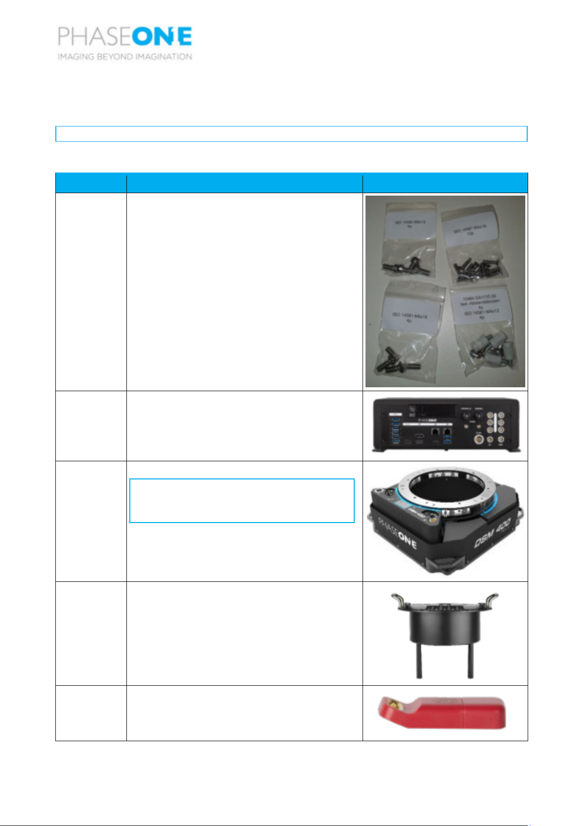
SOMAG
Pack of screws for the SOMAG stabilizer containing:
•4 x M6x12
•12 x M4x16
•4 x M6x16
•4 x M4x12 + 4 x spacer bolts
50202034
1 x iX Controller MK4 pre-installed with iX Flight and
iX Capture.
70678000
SOMAG DSM 400 Stabilizer
Note
You can also use the GSM 4000 as a
stabilizer. See Section 4.2 - SOMAG
GSM 4000 Stabilizer.
70679000
1 x system frame.
70693000
1 x iX Plan software license dongle.

PAS 280
System Description and Operation Guide
2. What’s in the Box
Phase One Confidential
Page 7 of 47
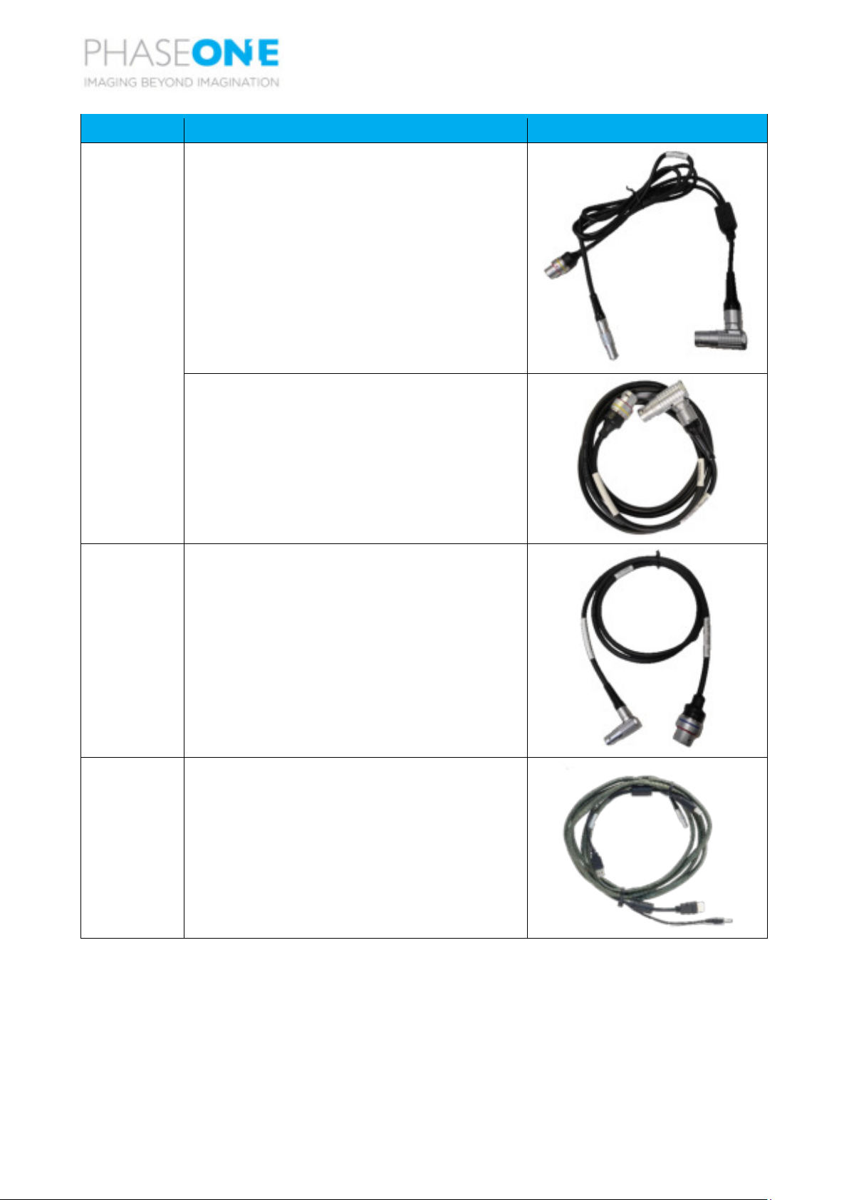
Part No.
Item
Image
70694000
1 x license iX Flight pre-installed on iX Controller.
73233000
2 x iX Controller USB 3.0 to iXM-RS 280F camera
USB-C cable.
(3 x if also using iXM-RS150F achromatic 50mm RS
camera).
75007000
1 x camera to camera multisync cable.
(2 x if also using iXM-RS150F Achromatic 50mm RS
camera).
75010000
1 x iX Controller to camera trigger cable.
75011000
1 x aircraft to iX Controller and stabilizer power
cable.
75012000
2 x iX Controller to iXM-RS 280F camera power
cable.
(3 x if also using iXM-RS150F achromatic 50mm RS
camera).
PAS 280
System Description and Operation Guide
2. What’s in the Box
Phase One Confidential
Page 8 of 47
Part No.
Item
Image
75014000 (for
DSM 400
stabilizer)
OR
1 x POS AV to iX Controller and DSM 400 stabilizer
comm cable.
75088000 (for
GSM 4000
stabilizer)
1 x POS AV to GSM 4000 stabilizer comm cable.
75015000
1 x POS AV to camera Event/MEP cable.
75021000
1 x iX Controller to pilot monitor Power + Video/USB
cable.

PAS 280
System Description and Operation Guide
2. What’s in the Box
Phase One Confidential
Page 9 of 47
Part No.
Item
Image
75022000
1 x iX Controller to operator monitor Power + Video
+ USB cable.
75023000
1 x 7” pilot monitor.
75024000
1 x 15.6” operator monitor.
75035000
1 x POS AV to iX Controller Ethernet cable.
75036000
1 x iX Controller to POS AV power cable.
76000600
1 x Microsoft all in 1 Keyboard and trackpad and
USB dongle.

PAS 280
System Description and Operation Guide
2. What’s in the Box
Phase One Confidential
Page 10 of 47
Part No.
Item
Image
76000700
1 x seat mount adapter for the operator monitor.
76004200
1 Applanix AV510M POS AV.
Note
You can also use the POS AV 310 (Part
No. 76004100) or POS AV 610 (Part
No. 76004300) as the POS AV. See
Section 4.3 - Applanix POS AV Models.
76014600
Trimble AV39 antenna, coaxial cable and mounting
screws.
86718900
1 x USB dongle with iX software suite, and metric
calibration information.
86720400
1 x iX Premium warranty booklet, detailing warranty
coverage for all installed camera and lenses.
72181000
(camera back
+ lens)
and
73110000
(NIR filter)
1 x iXM-RS150F camera pre-installed and calibrated
with RS-50mm lens and NIR filter.
Note
This optional camera is used in a 4-
band configuration.

PAS 280
System Description and Operation Guide
2. What’s in the Box
Phase One Confidential
Page 11 of 47
Part No.
Item
Image
72336000
(camera back)
and
73121000
(lenses)
1 x iXM-RS 280F camera pre-installed and calibrated
with two RS-90mm lenses.
2.1 Product Identification
To enable support for your system, you must identify and record the model and serial numbers for each of
the following components:
•Cameras: the model number and serial number is located on two labels in the middle section joining
both cameras.
•Stabilizer: model number and serial number is located on a label on the stabilizer.
•Applanix POS AV: model number and serial number is located on a label on the unit.

PAS 280
System Description and Operation Guide
3. System Overview
Phase One Confidential
Page 12 of 47
3System Overview
The PAS 280 is a large format, photogrammetric, large area coverage system, with a central projection
resolution of 20,150 x 14,118 pixels using the latest BSI CMOS sensors.
Figure 1. iMX-RS 280F Assembled System
3.1 Hardware
3.1.1 iXM-RS 280F Camera Head and Lenses
The iXM-RS 280F camera head uses two BSI CMOS sensors operated through two 90mm Rodenstock lenses.
The RS-280F camera produces a geometrically accurate 284 MP central projection image. The iXM-RS 280F
can capture 2 frames per second.
Figure 2. iMX-RS 280F Camera

PAS 280
System Description and Operation Guide
3. System Overview
Phase One Confidential
Page 13 of 47
3.1.2 SOMAG DSM 400 Stabilizer
The SOMAG is a high-performance gyro-stabilized platform that compensates for roll, pitch and drift
movements in real-time. The dynamic reaction times and the compensation ability of this platform ensures
your imagery remains fully vertical even in challenging conditions, while maintaining the high levels of
accuracy and efficiency.
SOMAG DSM 400 Stabilizer is an electromechanical gimbal system.
Figure 3. SOMAG DSM 400 Stabilizer
INTERFACE
POWER
SWITCH
POWER
SOCKET

PAS 280
System Description and Operation Guide
3. System Overview
Phase One Confidential
Page 14 of 47
3.1.3 System Frame
The system frame enables mounting of the cameras and iX Controller. The frame legs allow placing the
system frame on a maintenance bench while maintaining sufficient clearance for the camera lenses.
Figure 4. System Frame
3.1.4 Applanix POS AV
The Applanix Position and Orientation System for Airborne Vehicles (POS AV) provides navigation and
orientation data for geocoding and georectifying airborne sensor information.
Data such as geographic position (latitude, longitude and attitude), velocity, acceleration, angular rate,
orientation (roll and pitch), heading and performance metrics are available in real-time and through post-
processing.
The POS AV System is comprised of:
•POS Computer System (PCS)
•Inertial Measurement Unit (IMU)
•PCS-IMU cable (Applanix P/N 10005248-5) supplied with IMU.
For information on Applanix POS AV models supported, see Section 4.3 - Applanix POS AV Models.
Figure 5. Applanix POS AV and IMU
Cable
clamps
Mounting Pedestals for
the iX
-Controller
Carry
handles
System
Frame
legs

PAS 280
System Description and Operation Guide
3. System Overview
Phase One Confidential
Page 15 of 47
3.1.5 iX Controller MK4
The iX Controller is the communication center, and 1 TB data storage for the PAS. The Microsoft
Windows 10-based system is responsible for controlling power, and communication for all ancillary
systems. The storage solution consists of 2 x 500 GB SATA SSDs.
Figure 6. iX Controller Mk4
3.1.6 Trimble AV39 Antenna
The Trimble AV39 antenna is a lightweight, TSO certified antenna that provides centimeter precision with
superior phase center repeatability. The antenna is powered by the POS AV via a coaxial cable supplied with
the antenna.
Figure 7. Trimble AV39 Antenna
Lockable SATA SSD storage
device accommodates 2 x
500 GB SATA SSD devices
Ethernet
ports
USB slots with
lockable cable
solution for
transmission of
imagery data
HDMI and DP
ports for
monitors
USB port for
keyboard
dongle
Individual circuit
breakers for power
distribution control
Serial comm port
for stabilizer
communications
Power outlets for
system
components
I/O comm port for
trigger signal
PAS 280
System Description and Operation Guide
3. System Overview
Phase One Confidential
Page 16 of 47
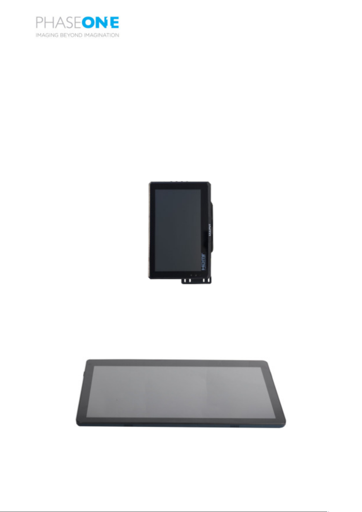
3.1.7 Monitor Kit
The monitor kit allows full control and flight feedback of the entire system, without any additional interface
devices attached. The monitor kit consists of the following monitors:
•pilot monitor
•operator monitor
3.1.7.1 Pilot Monitor
The 7” pilot monitor provides all flight information from iX Flight, ensuring that the pilot has all required
information to conduct a successful survey mission. The touch screen allows the pilot to perform several
quick-access operations in iX Flight (zoom, ± line number).
Figure 8. Pilot Monitor
3.1.7.2 Operator Monitor
The 15.6” operator monitor provides all required information from iX Flight and iX Capture, ensuring the
operator can control all aspects of the flight, including, run selection, camera control, and data
management using the touch screen.
Figure 9. Operator Monitor

PAS 280
System Description and Operation Guide
3. System Overview
Phase One Confidential
Page 17 of 47
3.2 Software
3.2.1 iX Plan (12.2 or higher)
With its intuitive GUI and multiple control functions, iX Plan allows you to easily generate flight plans. It
enables fast import of digital terrain models (DTM), base maps, project shapes and ground control points,
and includes a database of Phase One sensors.
iX Plan allows you to design effective flight plans. It automatically calculates flight lines and trigger points
based on sensor parameters, project parameters, and mapped terrain height. You can easily place flight
lines, edit existing ones and enable automatic planning.
iX Plan shows existing ground control points and supports the identification and positioning of new ones.
iX Plan can be installed on any PC running Windows 8.1 or higher.
Note
The iX Plan license USB dongle supplied with the PAS 280 aerial system must be inserted in
the PC running iX Plan.
3.2.2 ix Flight (12.3 or higher)
iX Flight uses iX Plan data to manage and guide the precise execution of aero-photography flight. Using the
pilot and operator monitors, the pilot can easily maintain precise trajectory by following altitude and
localizer instructions, while the operator manages the flight, controls the order of passes, tags images and
start/stops image collection. In the PAS 280 system, iX Flight is pre-installed on iX Controller.
For detailed information on using iX Flight, see the iX Flight User Guide provided with your PAS 280 aerial
system.
3.2.3 iX Capture (3.4.5 or higher)
iX Capture is a professional capture and RAW converter software that provides full control over the
cameras installed on the PAS 280 aerial system. It enables the operator to easily monitor and control every
aspect of aerial digital data acquisition using the operator monitor.
iX Capture enables you to capture, monitor, and process images in a fast, flexible, and efficient workflow.
When the optional iXM-RS150F camera with a NIR filter is also installed, iX Capture also generates 3 and 4
band CIR and NDVI TIFF files from files captured by both cameras (RGB and NIR). iX Capture is pre-installed
on iX Controller.
For detailed information on installing iX Capture on another PC and using iX Capture, see the iX Capture
User Guide provided with your PAS 280 aerial system.
3.2.4 Licensing
Software licensing is enabled as follows:
•iX Plan - software license is enabled through the USB dongle.
•iX Flight - software licenses are preinstalled on the controller.
•iX Capture - license is free.
PAS 280
System Description and Operation Guide
3. System Overview
Phase One Confidential
Page 18 of 47
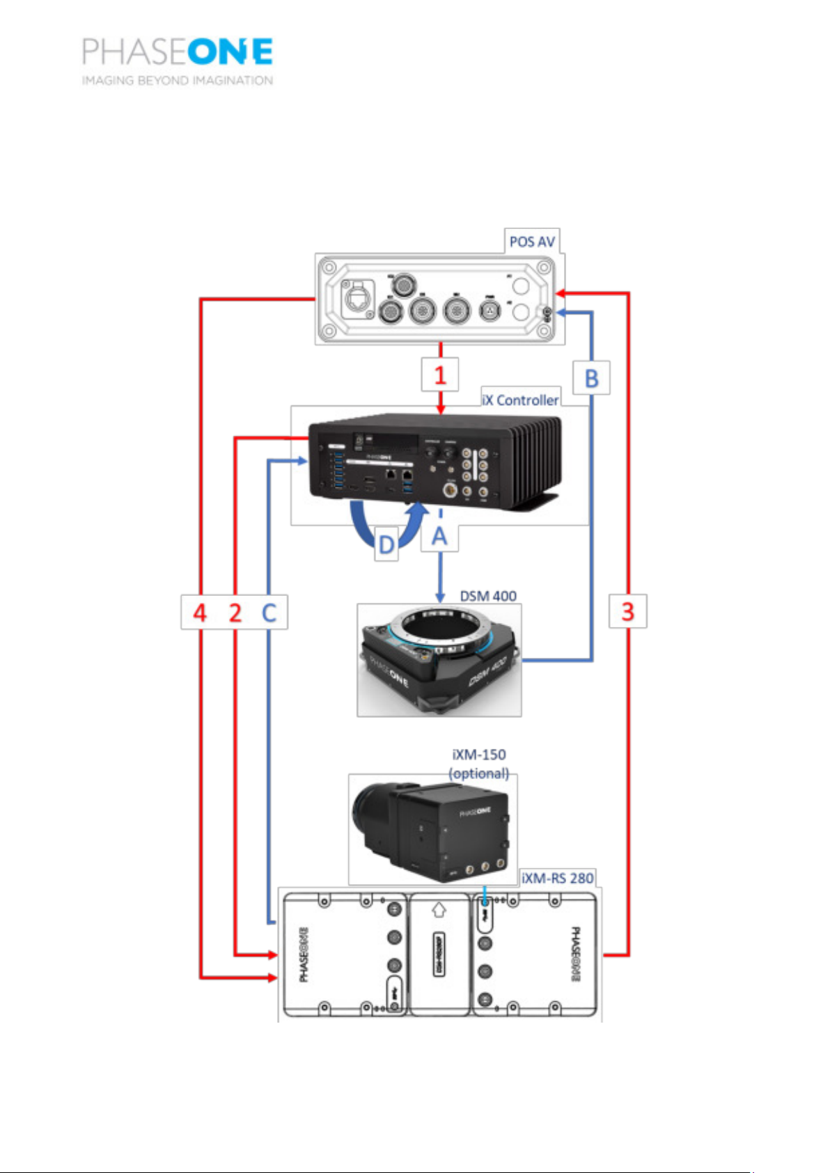
3.3 Dataflow
Figure 10 and Table 2 details the dataflow for a PAS 280 system with a DSM 400 stabilizer. For detailed
connection instructions, see Section 5.4 - Electrical Structure/Cabling.
Figure 10. Dataflow for PAS 280 System with DSM 400 Stabilizer

PAS 280
System Description and Operation Guide
3. System Overview
Phase One Confidential
Page 19 of 47
Note
See Table 2 for explanation of signals.
Table 2. Dataflow for PAS 280 System with DSM 400 Stabilizer
Sequence
in Figure
10
Signal/Data
From
To
Protocol
Description
1
NMEA or
Applanix
GSOF
Applanix
POS AV
iX
Controller
NMEA or
GSOF
over
TCP/IP
Applanix POS AV sends NMEA data
required by iX Flight to calculate
aircraft position and flight director.
2
Camera
trigger
iX Flight
Camera
Analog
I/O
discrete
iX Flight (in iX Controller) calculates
when to take a picture (based on
NMEA/GSOF data received from
Applanix POS AV) and issues a trigger.
3
MEP (Mid
Exposure
Pulse)
Camera
Applanix
POS AV
Discrete
Camera sends an event input to the
POS AV when the picture is taken.
4
Event data
Applanix
POS AV
Camera
RS-232
POS AV sends event metadata to
camera for image metadata.
A
(ongoing)
Start/Stop
pass
iX Flight
SOMAG
DSM 400
stabilizer
RS-232
•iX Flight (in iX Controller) sends
angle data to SOMAG DSM 400
stabilizer for stabilization.
•iX Flight (in iX Controller)
calculates Start of Line and before
reached, sends "Stab" command
to SOMAG DSM 400 stabilizer.
•iX Flight (in iX Controller)
calculates End of Line and after
reached, sends "Manual"
command to SOMAG DSM 400
stabilizer.
B
(ongoing)
GIM01
SOMAG
DSM 400
stabilizer
Applanix
POS AV
RS-232
SOMAG DSM 400 stabilizer platform
sends GIM01 message with platform
angles to the POS AV for registration
in T04 files.
C
(ongoing)
Images
Camera
iX
Controller
USB
Images taken by camera transferred
to iX Controller SSD.
D
(ongoing)
Internal
IX Flight
IX Capture
Internal
TCP/IP
iX Flight sends line number and image
in the line number to iX Capture for
tagging image filenames.

Other manuals for PAS 280
1
Table of contents
Other PhaseOne Drone manuals


