Phason LDB-2 User manual

User manual and
installation guide

ii
Table of contents
Introducing the Light Dimmer Box.............................................................................................................3
Features .................................................................................................................................................3
Becoming familiar with the Light Dimmer Box ..........................................................................................4
Menus and displays...............................................................................................................................5
What you need to know before installing the LDB-2 .................................................................................6
Understanding power surges and surge suppression..........................................................................6
Electrical ratings ....................................................................................................................................6
Installing your control ................................................................................................................................7
Mounting your control ...........................................................................................................................7
Control board layout..............................................................................................................................8
Connecting lights to the variable AC .....................................................................................................9
Connecting lights to the variable DC.....................................................................................................9
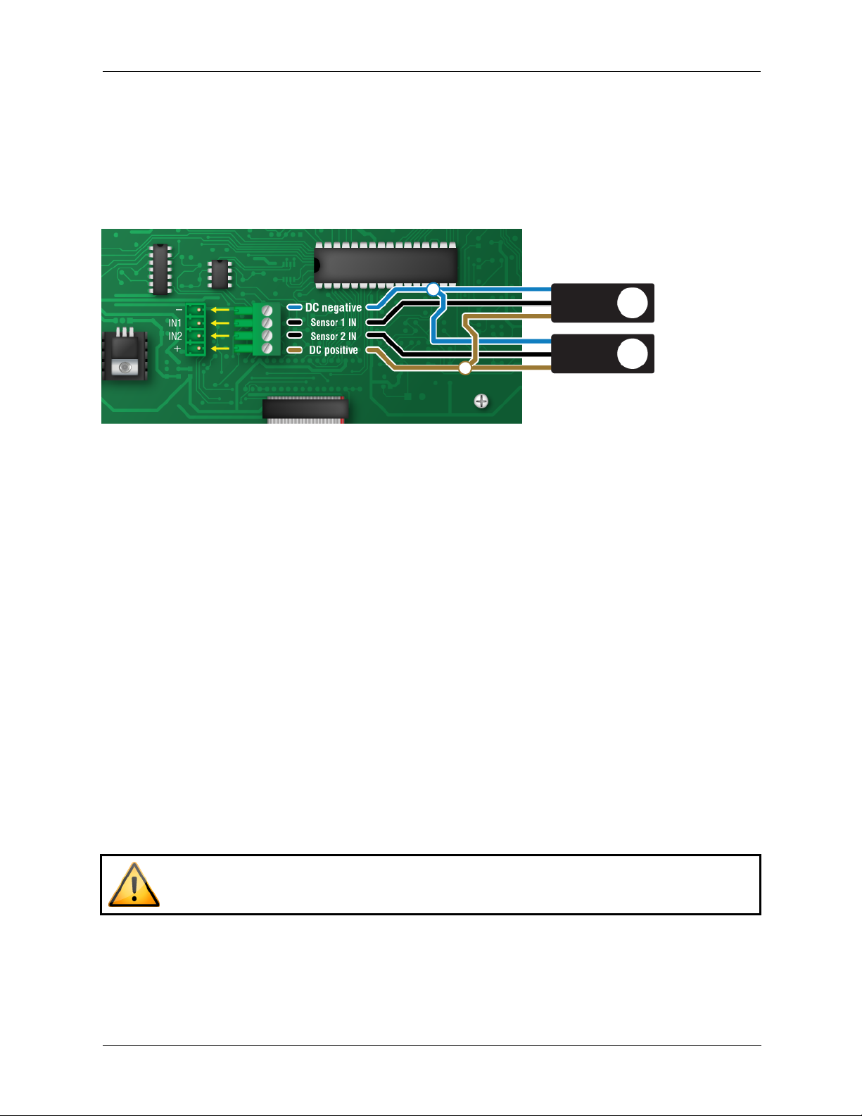
Connecting DOL 16 light sensors........................................................................................................10
Verifying the installation.......................................................................................................................10
Programming the Light Dimmer Box.......................................................................................................11
Operating frequency............................................................................................................................11
Control time .........................................................................................................................................12
Control mode.......................................................................................................................................12
Light program ......................................................................................................................................13
Using and maintaining the Light Dimmer Box.........................................................................................17
Current day ..........................................................................................................................................17
Manual override ...................................................................................................................................18
Light output calibration........................................................................................................................19
Factory defaults ...................................................................................................................................20
Saving and restoring settings..............................................................................................................21
Updating the firmware .........................................................................................................................22
Additional information..............................................................................................................................23
Replacement kits .................................................................................................................................23
Optional accessories ...........................................................................................................................23
Troubleshooting...................................................................................................................................26
Light program worksheets...................................................................................................................27
34141000
Copyright Phason Inc.
All rights reserved.
Printed in Canada

Phason Light Dimmer Box
3
Introducing the Light Dimmer Box
Phason’s Light Dimmer Box (model LDB-2) is designed around its easy-to-use functionality and
ability to control LED, CFL, or incandescent lights. The LDB-2’s large 4-line, 20-character display is
bright and easy to read, and the 4-button keypad makes it a breeze to navigate through the menu
and program the control.
Whether you are using the LDB-2 to control a light schedule for your poultry, swine, dairy, or
greenhouse facility, the Light Dimmer Box is sure to exceed your expectations.
Features
LED, CFL, and incandescent light compatibility
Two automatic modes:
Power mode controls by 0 to 100% power output
Sensor mode controls by measured LUX output
Requires DOL 16 light sensor
Configurable 365-day lighting program
Independent programs for each channel
Up to 20 schedules/lighting periods, per control mode
Up to 12 events per schedule
Separate ramp-up and ramp-down durations
Automatic program restart option
Manual override
Two variable AC channels
Two DC-signal channels
Two disconnect relays
Two light sensor connections
Light output calibration
Four-line, 20-character backlit LCD display
Real-time clock with power-failure settings protection
NEMA 4X enclosure (corrosion resistant, water resistant, and fire retardant)
CSA approval
Limited warranty (two years)

Light Dimmer Box Phason
4
Becoming familiar with the Light Dimmer Box

Phason Light Dimmer Box
5
Menus and displays
Main display
Shows the program status and time
Press Select to go to the main menu.
Main menu
Provides access to information and settings.
Press Up or Down to move through the menu.
Press Select to access an item.
Current day
Move forward or backward in your lighting program. For more
information, read Current day on page 17.
Diagnostics menu
Manually adjust the output. For more information, read Manual
override on page 18.
Allows you to calibrate the minimum and maximum light output. For
more information, read Light output calibration on page 19.
Light program menu
Provides access to all light program settings and configuration. For
more information, read:
Control mode on page 12
Light program on page 13
Configuration menu
Provides access to configuration. For more information, read:
Control time on page 12
Operating frequency on page 11
Saving and restoring settings on page 21
Factory defaults on page 20
Updating the firmware on page 22
About display
Shows the version and date of the firmware.
Day 001 16:30:25
Ch:1 Out: 80%
State:Normal
Schedule:01 Event:04
MAIN MENU
1 Current Day
2 Diagnostics
3 Light Program
4 Configuration
5 About
Select Channel: 01
Current Day: 001
DIAGNOSTICS
1 Channel1 Override
2 Channel2 Override
3 Calibrate
LIGHT PROGRAM
1 Control Mode
2 Event List
3 Restart Day
4 Rise Duration
5 Fall Duration
CONFIGURATION
1 Time
2 Frequency
3 Save Settings
4 Restore Settings
5 Factory Defaults
6 Update Firmware
Light Dimmer Box
LDB-2
V#.##
##/##/####

Light Dimmer Box Phason
6
What you need to know before installing the LDB-2
It is important that you read the following sections before you install your control.
Understanding power surges and surge suppression
Power surges can be caused by external influences (for example, lightning or utility distribution
problems) or they can be caused internally (for example, starting and stopping inductive loads such
as motors).
One of the most common causes of power surges is lightning. When lightning strikes the ground, it
produces an enormously powerful electromagnetic field. This field affects nearby power lines, which
transmit a surge to any device connected to it, such as lights, computers, or environmental controls
like your Light Dimmer Box. Lightning does not have to strike a power line to transmit a surge.
If you do not install external surge suppression devices, you risk damage to the
electronics inside your LDB-2, which may cause your LDB-2 to fail.
Because it is not possible to completely protect this product internally from the
effects of power surges and other transients, we highly recommend that you
install external surge suppression devices. For specific recommendations, see
your electrical contractor.
If you do not take these precautions, you acknowledge your willingness to
accept the risk of loss or injury.
Electrical ratings
Control power
120/230 VAC, 50/60 Hz
Fuse: 250 V, 1 A fast-acting glass
Variable AC
1000 watts at 120 VAC, 2000 watts at 230 VAC
8.5 A at 120/230 VAC, general-purpose (resistive)
Fuses: 15 A, 250 VAC ABC-type ceramic
Relays
1/3 HP at 120 VAC, 1/2 HP at 230 VAC
360 W tungsten at 120 VAC
Fuse: 12 A, 250 VAC ABC-type ceramic
Variable DC signals
0 to 10 V, 50 Ω, 200 mA
Alarm relay
0.4 A at 125 VAC, 2.0 A at 30 VDC, resistive load
0.2 A at 125 VAC, 1.0 A at 30 VDC, inductive load
Variable AC lights must be on the same phase as the control.

Phason Light Dimmer Box
7
Installing your control
Before connecting the incoming power, switch OFF the power at the source. Do not
switch ON the power until you have finished all wiring and verified all equipment is
properly connected and free of obstructions.
Use the electrical knockouts for bringing wires or cables into or out of your
control’s enclosure. Do not make additional holes in the enclosure; this can
damage the watertight seal or control components and void the warranty.
Before connecting the power, set the voltage selection switch to the correct
voltage.
Mounting your control
1. Select a location for your control.
Make sure you have enough cable and wire to
reach all the equipment you want to control.
2. Remove the screws from the front cover and
then gently lift it off.
3. Mount the enclosure to a wall using the four
screws provided with the control. Insert the
screws into the large holes in each corner of the
box and then tighten.

Light Dimmer Box Phason
8
Control board layout
Control fuse: The fuse is 250 V, 1 A fast-acting glass.
Voltage selection switch: Set the switch to the correct supply voltage before installing your control.
Display cable: Make sure the ribbon cable from the display is properly connected.
Sensor terminal: This terminal is not used
Variable DC terminals: Connect lights requiring a 0 to 10 V DC signal for control.
Alarm relay terminal: Connect an external alarm system or siren to this terminal.
Slave connectors: You can connect optional Phason Slave Units to these connectors.
Variable AC terminals: Connect AC powered lights. AC powered lights must be on the same phase as the control.
Disconnect relay terminals: Connect as a disconnect switch.
Incoming power terminal: Connect the incoming power (120/230 VAC, 50/60 Hz).
1
2
3
4
5
6
7
8
9
10
2
3
4
1
6
10
5
7
8
9

Phason Light Dimmer Box
9
Connecting lights to the variable AC
The relays follow the variable circuits and
act as disconnect switches. RLY 1 is for
VAR1; RLY 2 is for VAR2. When the
output is 0%, the relay is open (off). When
the output is 1% or higher, the relay is
closed (on).
Variable AC lights must be
on the same phase as the
control.
Connecting lights to the variable DC
The variable DC outputs are for controlling
AC-powered, dimmable lights requiring a 0
to 10 V DC signal.
The relays follow the variable circuits and
act as disconnect switches. RLY 1 is for V3;
RLY 2 is for V4. When the output is 0%,
the relay is open (off). When the output is
1% or higher, the relay is closed (on).

Light Dimmer Box Phason
10
Connecting DOL 16 light sensors
You can connect an optional DOL 16 light sensor. Light sensors allow you to take advantage of the
LDB-2’s ability to control by lux output and adjust according to ambient light.
Sensor 1 is for VAR 1/V3. Sensor 2 is for VAR 2/V4.
Verifying the installation
After installing and connecting equipment, verify the installation by following the steps below.
1. Make sure the voltage selection switch is in the correct setting.
2. Make sure all wires are properly connected to the correct terminals. Make sure you know which
piece of equipment is connected to each relay.
3. Make sure the display cable is properly connected.
4. Place the cover on the control and then tighten each screw a couple turns using your fingers.
5. Switch on the power to your LDB-2.
When the power comes on, the control should show a Power Fail message and then
show the main display. If the main display does not show, go back to step 1.
6. Test the equipment using manual override. For more information, read Manual override on page
18.
7. Tighten the four screws in the cover.
Do not over tighten the screws. Avoid using power screwdrivers or drills.

Phason Light Dimmer Box
11
Programming the Light Dimmer Box
Programming the Light Dimmer Box means entering in the information it will need to control lights
according to your specifications. Below is the recommended order of programming your control.
1. Operating frequency, only if using 50 Hz, (below)
2. Control time (on page 12)
3. Control mode (on page 12)
4. Light program (on page 13)
You can use an LDB-2 Saver to program controls in seconds. For more information,
read LDB-2 Saver on page 24.
Operating frequency
In North America, utility companies supply power at 60 Hz. In some areas of the world, power is
supplied at 50 Hz. The control is set to 60 Hz at the factory.
To change the operating frequency
1. In the Configuration menu, press Down until the
cursor is beside Frequency, and then press
Select.
2. Press Select.
3. Press Up or Down to switch between 50 and 60 Hz,
and then press Select.
4. Press Back until you reach the menu or display you
want.
CONFIGURATION
1 Time
»2 Frequency
3 Save Settings
Frequency: 60 Hz

Light Dimmer Box Phason
12
Control time
Because the Light Dimmer Box switches relays on or off at specific times, it is important that the
control time be correct. The Light Dimmer Box uses 24-hour time.
To change the control time
1. In the Configuration menu, press Down until the
cursor is beside Time, and then press Select.
The display shows the current time.
2. Press Select.
The hours flash.
3. Press Up or Down to adjust the hour, and then press
Select. Repeat for the minutes.
4. Press Back until you reach the menu or display you
want.
Control mode
The Light Dimmer Box has two automatic modes: power control and sensor control. Each channel
can have the same or different mode.
Power control mode
In power control mode, the Light Dimmer Box adjusts the power to the lights from 0 to 100%.
There is no adjustment for ambient light or other factors.
Sensor control mode
In sensor control mode, the Light Dimmer Box adjusts the output of the lights according to the
measured lux values. The control automatically adjusts for ambient light. Sensor control mode
requires an optional DOL16 light sensor. A separate light sensor is required for each channel using
sensor control.
Sensor mode has an alarm you can enable. When the control detects abnormal readings, it can
display a message on the screen.
CONFIGURATION
»1 Time
2 Frequency
3 Save Settings
Time: 15:30 hh:mm

Phason Light Dimmer Box
13
To select the control mode
1. In the Light Program menu, press Down until the
cursor is beside Control Mode, and then press
Select.
2. Press Select.
3. Press Up or Down to select the channel, and then
press Select.
4. Press Up or Down to select the mode you want to use,
and then press Select.
If you selected power control, the process is
complete.
5. Press Select.
6. You have the option to enable or disable the sensor
alarm.
To change the setting, press Up or Down.
7. Press Select.
8. Press Back until you reach the menu or display you
want.
Light program
The light program consists of schedules, events, a rise duration, a fall duration, a start day, and an
end day. Each channel can run the same or different light programs. The following diagrams and
explanations will help you understand how the settings work together.
Schedules
Schedules operate on 24-hour cycles (days), from midnight to midnight. Schedules can be from 0 to
365 days. Setting a schedule to 0 days disables that schedule. At the end of a schedule, the next
schedule starts. If there are no more schedules, the control follows the setting for the restart day (see
the next page). The light program can have up to 20 schedules.
LIGHT PROGRAM
»1 Control Mode
2 Event List
3 Restart Day
Select Channel:
Channel: 1
Control Mode:
»Power Control

Light Dimmer Box Phason
14
Events
Events are times of day at which the light output starts to change. Each event has a time of day and
a light output. The time of day is in 24-hour time. There can be up to 12 events for each schedule.
Rise and fall durations
Rise duration is the amount of time it takes to increase the light level from one event to the next.
Fall duration is the amount of time to decrease the light level. The rise and fall durations can be
different from each other. There is only one rise duration and one fall duration; you cannot have
different durations for different events. The range for both is 1 to 100 minutes; the default is 1.
Restart day
The restart day determines what happens at the end of the light program. The restart day can be
from day 1 to 365, and can be set to disable or enable.
If you set the restart day to disable, at the end of the selected day, the light program does not restart
and the output goes to 0. If you set the restart day to enable, at the beginning of the selected day,
the light program restarts at schedule 1.
For example, if the restart day is set to 100, at the beginning of day 100, the light program restarts at
schedule 1, day 1.

Phason Light Dimmer Box
15
To set the rise and fall durations
1. In the Light Program menu, press Down until the cursor
is beside Rise Duration, and then press
Select.
2. If you need to choose a different channel, press Select.
The setting flashes.
3. Press Up or Down to change the channel, and then press
Select.
4. Press Up or Down to move to the duration line, and
then press Select.
5. Press Up or Down to adjust the setting, and then press
Select.
6. Press Back to return to the Light Program menu.
7. Repeat steps 1 to 6 for fall duration.
8. Press Back until you reach the menu or display you
want.
To set the restart day and status
1. In the Light Program menu, press Down until the cursor
is beside Restart Day, and then press Select.
If you only want to change the status, go to step 5. If
you want to change the day, continue with the next step.
2. Press Up or Down to select the channel you want to
adjust, and then press Select.
3. Press Up or Down to set the restart day, and then press
Select.
4. If you want to change the status, continue with the next
step. Otherwise, press Back to return to the Light
Program menu.
5. Press Down until Status is highlighted, and then
press Select.
6. Press Up or Down to switch between Enable and
Disable, and then press Select.
7. Press Back until you reach the menu or display you
want.
2 Event List
3 Restart Day
»4 Rise Duration
5 Fall Duration
Channel: 1
Rise Duration:
»005 minutes
LIGHT PROGRAM
1 Control Mode
»2 Event List
3 Restart Day
»Ch1 Restart Day: 2
Status :Disable
Ch2 Restart Day: 2
Status :Disable

Light Dimmer Box Phason
16
To program schedules
1. In the Light Program menu, press Down until the cursor is beside Event List, and then
press Select.
Schedule 1 displays. If you have not set up the schedule, the channel assignment will be Off.
2. Select the schedule you want to program and the channel assignment.
a. With the cursor beside Schedule, press Select.
The schedule number flashes.
b. Press Up or Down until the schedule you want displays, and then press Select.
The channel assignment flashes.
c. Press Up or Down select the channel assignment, and then press Select.
3. Set the start and end days.
a. Press Down until the cursor is beside Start, and then press Select.
The start day flashes.
b. Press Up or Down set the start day, and then press Select.
The end day flashes.
c. Press Up or Down set the end day, and then press Select.
4. If you want to program events, read the next section. If you are finished programming, press
Back until you reach the menu or display you want.
To program or edit events
1. In the Schedule screen, with the schedule you want to edit selected, press Down until the cursor
is beside the event you want to edit and then press Select.
The hour flashes.
2. Press Up or Down to adjust the hour, and then press Select.
The minute flashes.
3. Press Up or Down to adjust the minute, and then press Select.
The light output flashes.
4. Press Up or Down to adjust the light output, and then press Select.
The cursor returns to the beginning of the line and the event is saved.
»Schedule:01 Ch:1
Start:000 End:090
Active Events: 07
Event Time Light
The days the schedule starts and ends
The number of active events
The schedule number and channel assignment
Start:000 End:090
Active Events: 07
Event Time Light
»1 00:00 010
The event number, time of day the event starts, and
light output (in % or LUX) after the rise or fall

Phason Light Dimmer Box
17
5. Repeat these steps for each event you want to program.
6. When finished, press Back until you reach the menu or display you want.
The Light Dimmer Box organizes events automatically by time. If you program a
new event that is earlier than one you have already programmed, the control inserts
it at the correct time and then re-numbers the events.
Using and maintaining the Light Dimmer Box
After programming the Light Dimmer Box, it will operate according to your specifications.
However, there might be times when you need to service or maintain equipment, or perform other
tasks. Below is a list of these tasks you can perform.
Change the current day of the light program (below)
Manually override the light output (on page 18)
Save and restore settings from an LDB-2 Saver (on page 21)
Restore the factory defaults (on page 20)
Update the firmware (on page 22)
Current day
The real-time clock counts time (seconds, minutes, hours, days), up to 365 days and then starts at
day 1 again. Adjusting the current day allows you to move forward or backward in the light program.
To change the current day
1. In the Main menu, with the cursor beside
Current Day, press Select.
2. If the channel you want to change is not selected,
press Select.
3. Press Up or Down to select the channel, and then
press Select.
4. Press Up or Down to move the cursor beside
Current Day, and then press Select.
5. Press Up or Down to set the current day, and then
press Select.
6. Press Back until you reach the display you want.
MAIN MENU
»1 Current Day
2 Diagnostics
3 Light Program
»Select Channel: 01
Current Day: 001

Light Dimmer Box Phason
18
Manual override
Manual override is for testing the installation and equipment connected to your control. Manual
override allows you to adjust the output of the lights to a value between 0 and 100% power. If you
have DOL16 light sensor connected, the display will also show the measured lux reading. The output
remains at the displayed value until you exit.
When the control is in manual override, it does not operate lights according to
the time of day.
The control does not exit manual override automatically. To exit manual
override, you must return to the Diagnostics or Main menu.
When you exit manual override, the light level adjusts to normal operation
according to the ramp up or ramp down duration.
To use manual override
1. In the Main menu, press Down until the cursor is
beside Diagnostics, and then press Select.
2. Press Up or Down to select the channel you want to
override, and then press Select.
3. To override the output level:
a. Press Select.
b. Press Up or Down to adjust the output, and then
press Select.
4. If you have a light sensor connected and want to
override the sensor reading:
a. Press Up or Down to move the cursor beside the
sensor reading, and then press Select.
b. Press Up or Down to adjust the reading, and then
press Select.
5. When finished, press Back until you reach the menu
or display you want.
The control returns to normal operation when you
exit the manual override screen.
DIAGNOSTICS
»1 Channel1 Override
2 Channel2 Override
3 Calibrate
»Output Level:
000%

Phason Light Dimmer Box
19
Light output calibration
Calibrating the light output allows you to set the minimum light level for when the output is 1%, and
the maximum light level for when the output is 100%.
You can calibrate light output automatically if you have a DOL 16 light sensor
installed. For more information, see DOL 16 Light Sensor on page 23.
To calibrate light output manually
1. In the Main menu, press Down until the cursor is
beside Diagnostics, and then press Select.
2. Press Down until the cursor is beside
Calibrate, and then press Select.
3. To set the minimum output:
a. Press Up or Down until the cursor is beside the
output value and then press Select.
b. Press Select. Press Up or Down to select the
channel, and then press Select.
The control reduces the output to 001.
c. Press Up or Down to adjust the output, and then
press Select.
d. When finished, press Back to return to the
calibration menu.
4. To set the maximum output, press Up or Down to
move the cursor beside Maximum Output,
and then press Select. Follow the same instructions as
minimum output.
5. Press Back until you reach the menu or you want.
DIAGNOSTICS
1 Manual Override
»2 Calibrate
Minimum Output:
»001
Sensor Reading:
Channel:000LUX
CALIBRATE
»1 Minimum Output
2 Maximum Output
3 Auto Calibration

Light Dimmer Box Phason
20
To calibrate light output automatically
1. In the Diagnostics menu, press Down until the cursor
is beside Calibrate, and then press Select.
2. Press Up or Down to move the cursor beside Auto
Calibration, and then press Select.
3. Verify that the indicator light on the sensor is lit.
Press Select and then Up or Down to change the No
to Yes, and then press Select.
If the channel you want to calibrate is selected,
go to step 4.
4. Press Select. Press Up or Down to change the
channel, and then press Select.
5. Press Up with Down to move the cursor beside No,
and then press Select.
6. Press Up or Down to change the No to Yes, and then
press Select.
The control goes through the calibration process.
First the minimum and then the maximum are
calibrated. The results display when it is complete.
7. When finished, press Back until you reach the menu
or you want.
Factory defaults
When the Light Dimmer Box leaves the factory, it comes with default settings and configuration.
Schedules and events: erases all schedules and events for the current control mode (power or
sensor).
Configuration: resets all items except schedules and events.
Factory defaults: resets everything.
Is the indicator
light on the sensor
ON ?
»No
Select Channel:
»Channel 1
Start Calibration ?
No
Calibration Done !
--------------------
Min LUX:001 At 100
Max LUX:095 At 500
Table of contents
Popular Lighting Equipment manuals by other brands

Mega LED Lighting
Mega LED Lighting MJ-1018 instruction manual

Avlite
Avlite AV-OL-ILAB-UM-R Installation & service manual

Ikan
Ikan MB4-2PT-KIT quick start guide

Gradus Group
Gradus Group Impact FF-OSB60 instructions

CREE-LED
CREE-LED XLAMP XP Series Soldering & Handling

EuroLite
EuroLite LED DMX Tube 1m RGB IP20 user manual