1
CONTENTS
1. Introduction................................................. 1
2. Applications................................................ 1
3. Package Contents ..................................... 1
4. System Requirements................................. 1
5. Features....................................................... 2
6. Operation Controls and Functions............ 3
6.1 Transmitter Front and Rear Panels....... 3
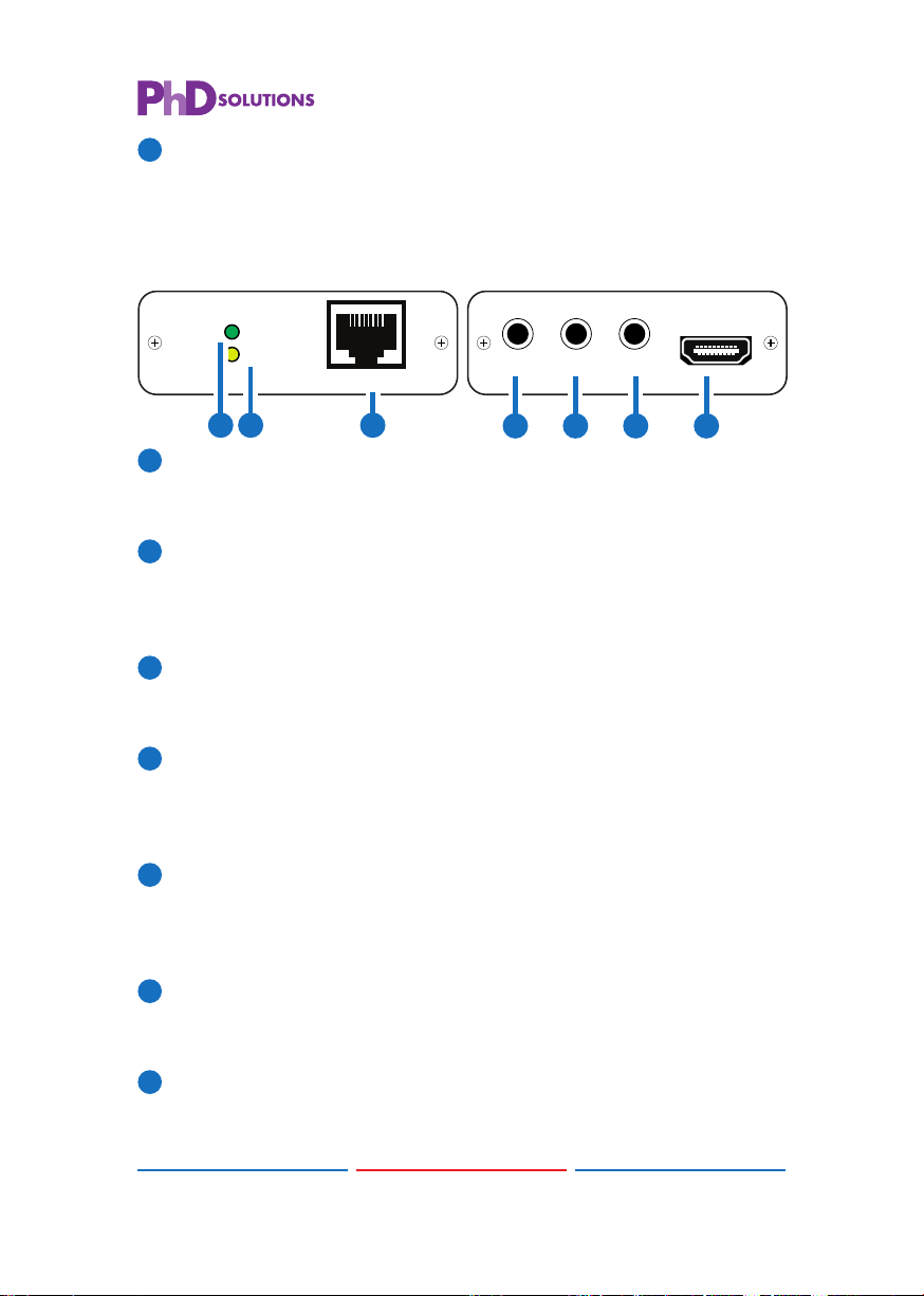
6.2 Receiver Front and Rear Panels .......... 4
6.3 IR Pin Assignment .................................. 5
6.4 D-Sub 9 Pin Defi nitions .......................... 5
7. Specifi cations ............................................. 6
8. Connection and Installation...................... 8
9. Acronyms .................................................... 9
The HDBaseT-LiteTM HDMI over single CAT5e/6 with bidirectional IR, RS-
232 & PoE transmitter and receiver set can make your home or offi ce
set-up more effi cient and easy to use. Uncompressed video and
audio can be transmitted up to 60 meters with the PoE function and
added benefi t of controls through the built-in RS-232 and IR ports. This
family design of HDBaseT™ technology allows a full usage of HDMI
and controls over CAT5e/6 cable.
2. APPLICATIONS
• Household entertainment sharing and control
• Lecture room display and control
• Showroom display and control
• Meeting room presentation and control for projector
• Classroom display and control
3. PACKAGE CONTENTS
• HDMI to CAT5e/6 with IR/RS232 & PoE x 1
• CAT5e/6 to HDMI with IR/RS232 & PoE x 1
• IR Blaster x 1
• IR Extender x 1
• 3.5Ø to RS-232 female cable x 1
• 3.5Ø to RS-232 male cable x 1
• 24V 1.25A DC Power Adaptor x 1
• Operation Manual
4. SYSTEM REQUIREMENTS
Input HDMI source equipment such as DVD/Blu-ray player/PC, output
display with HDMI input jack and connection cables of HDMI and
CAT5e/6.