Phenix Technologies 400P User manual

DCD 4100-10
USER’S MANUAL
CONJUNTO DE TESTE DIELÉTRICO DC
- 400P MODELO 4100-10
VERSÃO 5.4
Phenix Technologies Inc.
75 Speicher Drive
Accident, MD 21520
Copyright © Phenix Technologies, Inc
Rev 8/27/2021 ARF II

INTRODUÇÃO
A linha DC Hipot oferecida pela Phenix Technologies é robusta e adequada para uso em
campo ou laboratório. Ele é projetado para testar disjuntores, cabos, motores, geradores e
equipamentos de proteção. O teste DC é popular porque o equipamento é mais compacto
e mais leve do que o equipamento AC comparável.
Recursos de design e segurança
•Tensão de saída continuamente ajustável a 100kV DC.
•Bloqueio de tensão “Zero Start” e bloqueio de segurança externo.
•Medições de corrente de fuga disponíveis de 0,01 a 20.000 microampères CC.
•Cabo elétrico removível.
•A seleção por chave rotativa simplifica a operação.
•Compartimento para armazenamento de cabos integrado.
•Circuito de descarga integrado avaliado em 6 quilojoules.
•Leve, portátil e envolto em uma maleta de transporte de polietileno de alta densidade
resistente.
•Ponto de disparo de sobrecorrente ajustável de 10% -110% de cada faixa.
•Medidores LCD grandes e fáceis de ler.
•Disjuntor de entrada / interruptor de alimentação.
•Proteção térmica de sobrecarga (com reset) protegendo os circuitos primários do
transformador de alta tensão.
•Very low ripple at normal hi-pot test impedances.
Para especificações detalhadas completas, consulte a Seção 1-1.

ÍNDICE
DESCRIÇÃO SEÇÃO
1
2
3
4
5
6
7
8
9
10
11
12
INTRODUÇÃO
PERIGO / PRECAUÇÕES GERAIS DE SEGURANÇA
ESPECIFICAÇÕES TÉCNICAS
CONTROLES E INDICADORES
CONFIGURAÇÃO ELÉTRICA
INSTRUÇÕES DE OPERAÇÃO
PAINEL FRONTAL DE CONEXÃO GROUND-GUARD
CALIBRAÇÃO
SOLUÇÃO DE PROBLEMAS
ARMAZENAGEM DO EQUIPAMENTO
SIMBOLOS DO DIAGRAMA DE CIRCUITOS
SOBRESSALENTES RECOMENDADOS / LISTA DE PEÇAS
INFORMAÇÕES PARA PEDIDO DE PEÇAS
MATERIAL DEVOLVIDO
DIAGRAMAS ELÉTRICOS
DCD 4100-10
13

GENERAL SAFETY PRECAUTIONS
CUIDADO
ALTA TENSÃO
Este equipamento é capaz de fornecer TENSÕES POTENCIALMENTE LETAIS! A
operação inadequada ou práticas de teste podem resultar em ferimentos ou morte
para o operador ou pessoas próximas.
A operação do equipamento de teste de alta tensão deve ser realizada apenas por pessoal
familiarizado com os procedimentos de teste e segurança de ALTA TENSÃO. O operador
deste equipamento deve estar ciente de todos os perigos associados aos testes de alta
tensão. O operador é responsável por si mesmo e por outras pessoas nas proximidades da
área de teste.
Algumas práticas gerais de segurança para trabalhar com equipamentos de teste de alta
tensão foram listadas abaixo para sua referência.
A Phenix Technologies, Inc. não assume nenhuma responsabilidade pelo uso inseguro ou
impróprio de equipamentos de teste
•Familiarize-se com seu instrumento antes de realizar um teste real.
•Conheça a sua área de trabalho, verifique se todos os circuitos estão desenergizados e
bloqueados.
•Nunca trabalhe sozinho; trabalhe sempre com outro trabalhador qualificado.
•Marque toda a área de trabalho com barreiras e fita de advertência.
•Faça com que todo o pessoal esteja ciente de suas atividades de teste.
•Esteja ciente das condições perigosas que podem surgir da energização de um corpo de
prova.
•Nunca modifique o equipamento de teste, modificações no equipamento podem
apresentar um perigo desconhecido ou atrapalhar um recurso de segurança projetado.
•NÃO opere equipamentos danificados. Desligue a alimentação e não use o equipamento
até que a operação segura possa ser verificada por pessoal treinado para manutenção.

DCD 4100-10
1-1
SEÇÃO 1: ESPECIFICAÇÃO TÉCNICA
Entrada
120 VAC 10 Amps or 220 VAC 5 Amps, 50/60 Hz, monofásico (consulte a etiqueta de dados da
unidade)
Saída (máxima)
0-100 kilovolts dc
0-10milliamperes fuga resistiva contínua
0-20 milliamperes carregamento capacitivo de curto prazo
Capacidade de descarga interna: 6 kilojoules
Ciclo de Trabalho
Contínuo - Carregamento Capacitivo
Tipo de resfriamento Convecção natural.
Ripple:Menos de 2 por cento RMS com cargas de 30 Megohms e superiores de 10kV-100KV e
cargas capacitivas.
Saída: Saída negativa, padrão de aterramento positivo. Saída positiva disponível por pedido
especial. Circuito duplicador de tensão filtrada, equivalente à retificação de onda completa.
Temperatura ambiente de operação 0 a 40 graus Celsius.
Terminais de saída Cabo de alta tensão, blindagem protegida.
Medição
Voltimetro:
Amperimetro:
Saída Analógica
Indicador de Carga:
LCD 3 ½ DIGITOS , precisão de 0,5% da escala completa.
Faixa: 0 a 19,99 kV, 0-100,0 kV
LCD 3 ½ DIGITOS , precisão de 0,5% da escala completa.
Faixa de 0 a19.99µa, 199.9µA, 1.999mA, 19.99mA
1.5” ANALÓGICA
0-100% da indicação da faixa selecionada.
Tamanho e Peso
572 mm Lx 533 mm Px 419 mm A; 44.5* kg) *Para unidades 220 V : adicionar 4.5 kg

2-1
SEÇÃO 2: CONTROLES EINDICADORES
PAINEL DE CONTROLE
(Ref.aFigura2-1).
1. ENTRADA DE ALIMENTAÇÃO AC . Conecte em uma tomada adequadamente aterrada. Consulte a
etiqueta de especificações na unidade para obter os requisitos de tensão e corrente.
2. BLOQUEIO EXTERNO. Se desejar, remova o jumper do conector e substitua por contato (s) que devem
ser mantidos fechados durante o teste. Alguns exemplos incluem pedal, interruptor de segurança, , botão
de pânico, etc.
3. SOBRECARGA TÉRMICA. O disjuntor protege o primário do transformador de alta tensão. Se o disjuntor
desarmar, desligue a alta tensão e retorne o botão de controle de tensão a zero antes de reinicializar.
4. F1. Fusível
5. DISJUNTOR DE ENERGIA PRINCIPAL. Pressione I para conectar a alimentação, pressione O para
desconectar.
6. INDICADOR DE ALIMENTAÇÃO PRINCIPAL. Luzes para indicar que a energia está disponível para
teste.
7. Ajuste da corrente de trip: O dial ajusta de 1 a 11 correspondendo a aproximadamente 10% a 110% da
faixa de corrente de saída selecionada. A lâmpada de Corrente de Trip/Reset acende e a alta tensão é
desligada quando a corrente de saída excede a configuração, fazendo com que o circuito desarme. O
circuito também atua como proteção contra curto-circuito e sobrecarga na saída de alta tensão. Para
reativar a alta tensão, o controle de tensão deve ser retornado a zero e a chave Reset deve ser
pressionada para limpar o circuito de disparo de corrente.
8. Reset. A lâmpada de reset acende para mostrar que o circuito de desarme atual desarmou. Os circuitos
de alta tensão são desativados. O interruptor de reset momentânea deve ser pressionado para apagar a
lâmpada de reset para permitir que a alta tensão seja reaplicada após retornar o controle de tensão
para zero.
9. High Voltage On. Pressione para ligar a alta tensão. As condições necessárias para que a alta
tensão seja ativada são:
•Controle de tensão em Zero Start
•Malha de intertravamento externo fechada.
•Current Trip circuit Reset.
10. Alta tensão desligada. Pressione para desligar a saída de alta tensão. Em circunstâncias normais, o
controle de tensão deve retornar a zero, e a alta tensão deve cair perto de zero antes de desligar a alta
tensão. CUIDADO: Cargas capacitivas podem reter a tensão por um curto período após a alta tensão ser
desligada, enquanto o circuito interno libera sua carga para o aterramento. A lâmpada de alta tensão
desligada deve estar acesa antes que a alta tensão LIGADA possa ser ativada. As condições exigidas
para a iluminação são:
•External Interlock loop must be closed.
•Overcurrent Trip/Reset circuit must not be tripped. (Push Reset if circuit is tripped)
DCD 4100-10
2-2
CONTROLES E INDICADORES
CONTROL PANEL (Cont’d)
11. Output Voltage Control. Turn clockwise to increase output of test set. This control must be in the full
counterclockwise position (Zero Start) in order to turn High Voltage On. Under normal circumstances,
Voltage Control should always be returned to zero and voltage displayed on the voltmeter allowed to
decay to zero before pressing High Voltage Off.
12. ANALOG CURRENT INDICATOR. Meter displays current from 0-100% of range to give visual indications
of capacitive charging conditions or to show changing current conditions that are not easily determined
from digital meters.
13. CURRENTMETER. Displays current out of High Voltage Lead (#16) or into Return terminal depending
upon mode of measurement
14. VOLTMETER. Displays voltage output of test set in kilovolts.
15. VOLTMETER RANGE SELECTOR. Rotate to appropriate setting for test voltage.
16. CURRENTMETER RANGE SELECTOR. Rotate to desired range. With capacitive loads, selector will
normally be placed in highest current range and then ranged lower as appropriate.
17. GUARD TERMINAL. Connect to Ground terminal (#13) with Grounding Clip for Guard Mode operation.
Connect currents that need to bypass the currentmeter to this point. Low potential side of specimen must
be isolated from ground to use this mode and will be connected to Return post. See section on
Return –Ground –Guard for more information.
18. GROUND (GND) TERMINAL. Connects to facility ground. See (#12), (#14) and (#15) for more
information.
19. GROUNDING CLIP. The Grounding Clip must always be connected from the Ground post to either the
Return post or the Guard post. Do not operate the unit with the clip disconnected.
See Section 5 on Return –Ground –Guard for more information.
20. RETURN (RTN) TERMINAL. Connect to Ground terminal (#13) with grounding clip for normal operation.
Always connect low potential side of test specimen to this point. This is the metered connection point for
measuring current. This mode must be used if low potential side of test object is grounded or has a ground
reference. See section on Return –Ground –Guard for more
information.
21. HV OUTPUT LEAD. This lead is always attached to the high potential side of the specimen under test.

2-3
CONTROLES E INDICADORES
FIGURE 2-1
PHENIX
TECHNOLOGIES
TECHNOLOGIES
PHENIX

DCD 4100-10
3-1
SECTION 3: ELECTRICAL SET-UP
High Voltage Connection
1. Locate the desired placement for the test set. Prepare the main power input cable for plugging into the
proper facility power (i.e., 120 volts AC or 220 volts AC). Leave plug unconnected at this time.
2. Place currentmeter in desired mode of operation by connecting the jumper clip between Return (RTN) and
Ground (GND) or Guard (GRD) and Ground (GND) binding posts. The normal connection is between
Ground and Return. See Section 5 on Return-Ground-Guard for more information on this connection.
3. Connect the Ground (GND)” connection to facility ground using the ground test lead provided.
4. Connect the low potential side of test specimen to terminal labeled Return (RTN). Use red test lead
provided.
5. Connect the high voltage output cable to the high potential side of test specimen. CAUTION: Keep
shielded part of high voltage cable away from test specimen high voltage points.
6. Connect the input main power cable to appropriate power source. Check Technical Specifications tag on
unit, for proper input voltage.
7. Read and understand entire operating instructions before applying power.
WARNING:
Main Power switch on front panel must be in the OFF (O) position before proceeding. Make sure
Test object is de-energized and discharged.
WARNING:
Improper contact with the test leads on this equipment can cause harmful or fatal electrical shock.
Do not touch test leads while a test is in process. This equipment should only be operated by
someone familiar with high voltage testing and safety procedures.

4-1
SECTION 4: OPERATING INSTRUCTIONS
1. Ensure proper electrical set-up has been performed.
2. Check that the Voltage Control dial is set to "0" (Zero Start position).
3. Select the proper voltmeter range, currentmeter range, and current trip setting.
High Voltage Applied
4. Turn on the Control Main Power switch. The Power On lamp will illuminate.
5. Momentarily press the HV On pushbutton. The high voltage will be applied to the cable and the HV On
switch lamp will illuminate. (Zero Start and External Interlock Loop conditions must be met and Reset
lamp must be extinguished.
6. With HV On, rotate the Voltage Control dial and watch the Output Voltmeter and Output Currentmeter
until desired levels are reached.
Note: When testing samples that are largely capacitive in nature, it may be necessary to place
currentmeter range switch in the 20mA position. Operator must then slowly raise output watching the
currentmeter and allowing the test sample to "charge up".
7. Record data, if desired, and lower the Voltage Control to Zero after testing is completed. Use Discharge
or Grounding stick to discharge specimen or allow voltage to return to zero. Press HV Off button; high
voltage will be shut off and the HV (On) switch lamp will extinguish and the High Voltage Off/Ready lamp
will illuminate.
Overcurrent Failure
8. If an overcurrent situation occurs (output current exceeds Overcurrent Trip setpoint), the over-current
relay will activate, de-energizing the test set (High Voltage Off). To regain high voltage the Reset button
must be depressed and, the Voltage Control dial must be returned to zero. Press the HV On button
momentarily to turn High Voltage back on.
9. After all testing is completed; turn off the front panel Main Power switch. Remove the input power cable
from the facility power input.
10. CAUTION: Make certain that the test specimen is totally discharged and grounded before
removing test cables.
WARNING:
This equipment should only be operated by personnel familiar with high voltage testing and safety
procedures. Improper operation may result in injury or death and can cause damage to the unit or
test object.

DCD 4100-10
4-2
OPERATING INSTRUCTIONS
Calculating Meg-Ohms The Impedance of a test object can be determined by the formula:
V/I=R where voltage in Volts divided by current in Amps equals Resistance in Ohms.
Resistance divided by 1,000,000 then equals Meg-Ohms: R/1,000,000=Meg-Ohms
When voltages are in Kilovolts and currents are in Milliamps, a more direct method is to directly divide
Kilovolts by Milliamps to obtain the result directly in Meg-Ohms.
KV/mA=Meg-Ohms
Example: 10kv divided by 2mA equals 5Meg-Ohms
Many times, though, the current will be in micro amps. In this case, micro amps must first be converted to
milliamps, or the formula must be changed to accommodate micro amps.
Micro amps can be converted to milliamps by dividing by 1,000.
uA/1,000=mA Example: 50 uA/1,000=0.05mA. The result can now be used directly in the above
formula. 10kV divided by .05mA equals 200Meg-Ohms
An alternate method is to use the formula; Kilovolts divided by Microamps multiplied by 1,000 equals Meg-
Ohms.
KV/uA x 1,000=Meg-Ohms
Example: 10kV divided by 50uA times 1,000 equals 200Meg-Ohms

5-1
SECTION 5: RETURN-GROUND-GUARD CONNECTIONS
The unit contains a currentmeter feature useful in measurement of different current sources.
1. Return Mode (RTN) (Grounded Return Mode)
This is the standard measurement configuration. The Ground jumper is installed between the Ground
(GND) post and the Return (RTN) post. The low potential side of the test specimen is connected to
Return. It can initially be isolated from ground or tied to ground. When it is connected to Return in this
mode, it will be grounded through the Ground jumper if it was initially isolated from ground. This mode
measures all output current from the test set.
If the low potential side of the test specimen will not or can not be isolated from ground, Return Mode is
the hookup mode that must be used. Any connections made to Guard must be isolated from ground in
this mode and will bypass the currentmeter. All currents to Ground and Return will be measured in this
mode.
2. Guard Mode
In this mode, the Ground jumper is connected to the Guard post and Ground post. The low potential side
of the test specimen must be isolated from ground and connected to the Return post. Only current to the
Return post will be measured by the currentmeter. Any stray leakage currents to ground or from sources
connected to Guard will bypass the currentmeter and not be measured such as stray leakage currents to
ground, stray currents to shields or
housings tied to Ground or Guard, etc. In this mode, the low potential side of the specimen must be
isolated from ground. If the low potential side of the specimen can not or will not be isolated from ground,
this mode can not be used to accurately measure current flow.
NOTE: Do not operate unit with the ground jumper removed or not connected to either Return or Guard.
Make sure the Ground post is connected to a good earth ground. See connection diagrams (Figure 5-1)
on next page.

DCD 4100-10
5-2
RETURN-GROUND-GUARD CONNECTIONS
Figure 5-1

6-1
SECTION 6: CALIBRATION
All calibrations have been done at the factory. Periodic calibration of the output voltmeter and output
currentmeter should be done annually.
NOTE: Refer to Electrical Diagram Section for schematics pertaining to the model number of your test set.
Locating the Calibration Adjustments
The calibration points are shown in the following diagram.
1. Output Voltmeter
Connect a precision high voltage voltmeter across the output to ground on low range. Raise the output
to approximately 80% of range. Adjust the reading on the panel meter (M1) by means of potentiometer
R1 to a corresponding reading. Check Linearity and calibration at various other main points of the range
such as 20%, 40%, 60%, 100%. Repeat for High range, adjusting R2.
R101
10%
Ovld
R103
110%
Ovld
R235
Range
Ovld
R201
20mA
CM
R202
2mA
CM
R203
200uA
CM
R204
20uA
CM
R2
100kV
VM
R1
20kV
VM
CAUTION:
Calibration should only be done by persons familiar with High Voltage testing and safety
procedures.

DCD 4100-10
6-2
CALIBRATION
2. Output Currentmeter
It is necessary to connect adequately rated High Voltage loads (isolated from ground) to the high voltage
unit that will allow each full range current to be drawn at approximately 15% or higher output voltage.
This allows sufficient resolution to adjust current levels.
Place Binding Post Configuration in GUARD MODE. (Jumper clip is installed between Guard and
Ground posts.)
Connect a precision ammeter between the low potential side of the appropriate high voltage load and
the Return post. Select the low current meter range (20uA). Raise the output to approximately 80% of
range (16uA). Adjust the reading on the panel meter (M1) by means of potentiometer R204 to the
corresponding reading of the standard meter. Repeat for 200uA, 2mA, and 20mA ranges; adjusting
R203, R202, and R201 respectively. (High Voltage load will need to change when changing range).
An optional method is to use DC current injection between “RTN” and “GND”(Guard Mode). If using
this method, do not turn High Voltage ON!
3. Overcurrent
This calibration should not need adjustment (factory adjusted). If the overcurrent circuit is out of
calibration, perform the following steps.
a. With unit off, short the output terminal to ground through an appropriate currentmeter. (A High
Voltage Load will give better resolution and make calibration easier and more accurate. Minimum
recommended resistance: 100K ohm, 100 watt.).
b. Set the Current Trip potentiometer on the front panel to "1”and the current range switch to 20mA.
c. Turn on HV On and adjust the output current slowly until 10% of rated current (2mA) is displayed
on the currentmeter.
d. Adjust potentiometer R101 until the Reset lamp illuminates and high voltage is shut off.
e. Set the Current Trip potentiometer on front panel to "11."
f. Turn on HV On and adjust the output current slowly until 110% of rated current (22mA) is displayed
on meter.
g. Adjust potentiometer R103 until the Overload lamp illuminates and high voltage is shut off.
h. Repeat steps "b" through "g" as necessary until both settings are calibrated.
4. Range Overcurrent. R235 sets an overcurrent for the ranges and should be set to trip at approximately
112% of 2mA range.

7-1
SECTION 7: TROUBLESHOOTING
General
If the controls do not operate properly after having been used according to the instructions, the following hints
may help.
•Check main facility input power to the test set.
•Check indicating lamps. (Spare lamps are available through Phenix Technologies.)
•Check fuse-F1.
•Check all external plug connections on the test set.
Specific Problems Refer to appropriate electrical diagrams.
1. High Voltage cannot be turned on?
•Voltage Control dial is not in Zero Start position.
•External interlock circuit open.
•Current Trip setting too low, or needs reset.
•Current trip circuit damaged, won’t reset, try replacing U101 (LM311N)
•Faulty HV On switch, faulty HV Off switch.
•Relay K1 dislodged or faulty.
2. Voltage control inoperable?
•Tripped or faulty Thermal Overload.
•High voltage is not on (see number 1 above).
•Faulty Variable transformer "T1".
•Faulty High Voltage tank assembly.
3. Over current inoperable?
•Faulty U101 (LM311N).
•Faulty DC Power Supply circuit.
•Defective over current relay K101.
•Faulty R7 over current trip potentiometer.
4. Currentmeter inoperable?
•Improper connection of GUARD/GND/RETURN jumper (J1) for mode of operation.
•Improper connection of test specimen.
•Faulty U201 or U202 (LM348).
•Meter damaged.
•Faulty currentmeter range switch SW5.
•Faulty connection in currentmeter circuit.
•Faulty DC Power Supply Circuit.
5. Voltmeter inoperable?
•Meter damaged.
•No high voltage present at output.
•Faulty connection in voltmeter circuit.
6. No output voltage from high voltage section?
•Defective metering circuit.
•No input to voltage regulator section, possible problems with K1 relay or Thermal Overload.
•High Voltage Cable shorted to shield of cable.
•Faulty High Voltage Unit.

DCD 4100-10
8-1
SECTION 8: STORAGE OF EQUIPMENT
If the equipment will be stored for a prolonged period, the following precautions are recommended.
1. The equipment should be covered and kept in a warm, dry environment (95% maximum humidity, 5 to 50
Celsius).
2. In no case should the test unit be stored outdoors (unless previously specified in the original purchase
agreement).

9-1
SECTION 9: CIRCUIT DIAGRAM SYMBOLS
Dispositif De Sur
Interrupteur Normalement
Maintenu Ouvert
Interrupteur Normalement
Maintenu Ferme
Ouvert Momentanement
Ferme Momentanement
Interrupteur Normalement
DESCRIPTION
Condensateur
Unite d'amplificateur
Relais, Contacteur
Transformateur
Condensateur electrol
Transformateur de
Resistance Variable
Prise de Courant
Contact Normalement
Contact Normalement
Changement
Insrument Analogue
Diode Zener
Cable blinde
T Transformer
Device
Current Overload
Momentary Switch
Normally Open
Momentary Switch
Normally Closed
Normally Closed
Maintained Switch
Maintained Switch
Normally Closed
Normally Open
Normally Open
Thyristor
Zener
Diode
Analog Meter
Shielded Wire
Transistor
Changeover Contact
Relay Contact
Relay Contact
Connector
Terminal Block
DP
SW
SW
SW
SW
SCR
Z
D
TR
M
K
K
K
TB
X
Intensite
Diode
Transisteur
Thyristor
Borne
Ouvert
Ferme
Contact de
SYMBOLE ZU SCHEMA
SYMBOLES POUR SCHEMA DE CIRCUIT
CIRCUIT DIAGRAM SYMBOLS
Variable Resisitor
Resistor
Lamp, Indicator
Neon
Movistor
Motor
Inductor
Relay, Contactor
Circuit Breaker
Current Transfomer
Fuse
Electrolytic Capacitor
Bushing
Capacitor
Surge Arrestor
Amplifier
BSHG
LP
R
R
NE
MOV
MOT
CB
K
L
CT
F
C
SYMBOL
ARSR
C
REF
A
Tranversee
Parafoudre
Moteur
Parafoudre
Lampe
Resistance
Courant
Fusible
Interupteur
Self
DESCRIPTION
Parafoudre
Transformer
Oeffnungskontakt
Abgeschirmetes Kabel
UeberstromschutzEinheit
Schrittschalter
Druckschalter
(Schliesser)
Schrittshalter
(Oeffner)
(Schliesser)
(Oeffner)
Druckschalter
Analog Meter
Transistor
Thyristor
Diode
Zener
Losbare Klemme
Steckverbindung
Schlierskontakt
Umschaltkontakt
BEMENKUNG
Ueberspannungsableiter
Eleckrolytik kondensator
Stromtransformer
Durchfuehoung
Widerstand
Movistor
Meldeleuchte
Widerstand
Motor
Sicherung
Drossel, Spule
Relais, Schutz
Unterbrecher
Kondensator
Verstarker

DCD 4100-10
10-1
SECTION 10: RECOMMENDED SPARE PARTS
Phenix Technologies recommends that the customer purchase and stock the following parts for normal
maintenance of the unit. The recommended quantity should be sufficient to support the unit during normal
operation.
If the unit will be operated at an isolated site for an extended period or will be subjected to unusual stresses, a
larger quantity of parts should be stocked as spares. In such cases, contact Phenix Technologies for a
recommendation.
Current prices may be obtained by contacting the Parts Ordering Department at Phenix Technologies.
Part Name
Computer
Number
Recommended
Quantity
Digital Panel Meter, 3 ½ Digit LCD, 2V (M1,2)
1506400
1
Analog 1 ½” Charging Current Meter (M3)
1501016
1
Lamps, 60 V, EAO
1420150
5
EAO Momentary –1 POLE Switch (SW 2,34)
1860120
1
Limit Switch (SW7)
1866005
1
LM311N Comparator IC (U101)
1794493
2
OP400GP OP AMP (U201, 202)
1794105
2
Relay, Control (K1)
1700610
1
Fuse, 1 A, 250 V, (F1)
1603601
1
Power Input Cord
1077167
1
Binding Post- RED
1351102
1
Binding Post - GREEN
1351103
1
Binding Post - WHITE
1351104
1
High Voltage Cable Assy.
30070015
1
Return Cable Assy.
30080010
1
Ground Cable Assy.
30080011
1

10-2
4100-10 PARTS LIST
ITEM
DESCRIPTION
QTY
PART NO.
CONTROLS
C5, 6
.033 uF 630v Capacitor
3
1093300
CABLE-GROUND
20 FT. GROUND CABLE ASSY.
1
30080011
CABLE-HV
20 FT. HV CABLE ASSY.
1
30070015
CABLE-RTN
20 FT. RED RETURN CABLE ASSY.
1
30080010
CB1
CIRCUIT BREAKER, 10 AMP, 2-POLE
1
1601314
CB2
CIRCUIT BREAKER, 7AMP
1
1601420
CORD
INPUT POWER CORD
1
1077167
D2-D5
DIODE
4
1780025
F1
FUSE, 1 AMP
1
1603601
F1
FUSE HOLDER
1
1603920
J5
RECEPTACLE 14F PIN
1
1151156
J5
CONTACT PINS
J5
LP1 LENS
CLEAR LENS EAO
1
1422153
LP2 LENS
LENS, RED EAO
1
1422150
LP3 LENS
LENS, GREEN EAO
1
1422151
LP4 LENS
LENS, BLUE EAO
1
1422148
LP1 SOCKET
LAMP SOCKET EAO
1
1423300
LP1-4
LAMP 60V EAO
4
1420150
M1, M2
METER-DIGITAL, 3 ½ DIGIT LCD
2
1506400
M1-CM
METER PROTECTION BOARD ASSY.
1
31126500
M2-VM
METER PROTECTION BOARD ASSY.
1
31126502
M3
METER-ANALOG 1 ½”
1
1501016
MOV1
MOVISTOR, V130LA10A
1
1606100
P1
POWER INPUT RECEPTACLE
1
1153328
PCB Assy.
PCB1387: 4120-10 CNTRLS & METERING
1
31138707
PCB
PCB 1223 (MTG FOR R1-R5)
1
1112232
R7
POTENTIOMETER, LINEAR, 10K, 2W
1
1761098
R7 DIAL
BLACK STATOR
1
1355905
R7 DIAL
0-11 NUMBERED DIAL
1
1355910
R7 KNOB
BLACK KNOB
1
1355101
R7 KNOB
KNOB CAP
1
1355102
SG1, 2
SPARK GAP-90V
2
1605110
SW/LP 2,3,4
SWITCH, PUSHBUTTON, MOMENTARY, 1-POLE
3
1860120
SW5
SWITCH, ROTARY, 3 POLE, 4 POS.-SH.
1
1863042
SW6
SWITCH, ROTARY, 2 POLE, 2-6POS.-SH.
1
1863047
SW5, 6 KNOB
KNOB, ¼”
2
1355310
SW7
SWITCH, ROLLER, CAM, ZERO START
1
1866005
Other manuals for 400P
1
This manual suits for next models
1
Table of contents
Other Phenix Technologies Measuring Instrument manuals

Phenix Technologies
Phenix Technologies KVM 100A User manual

Phenix Technologies
Phenix Technologies KVM100 User manual

Phenix Technologies
Phenix Technologies KVM50A User manual

Phenix Technologies
Phenix Technologies KVM300 User manual

Phenix Technologies
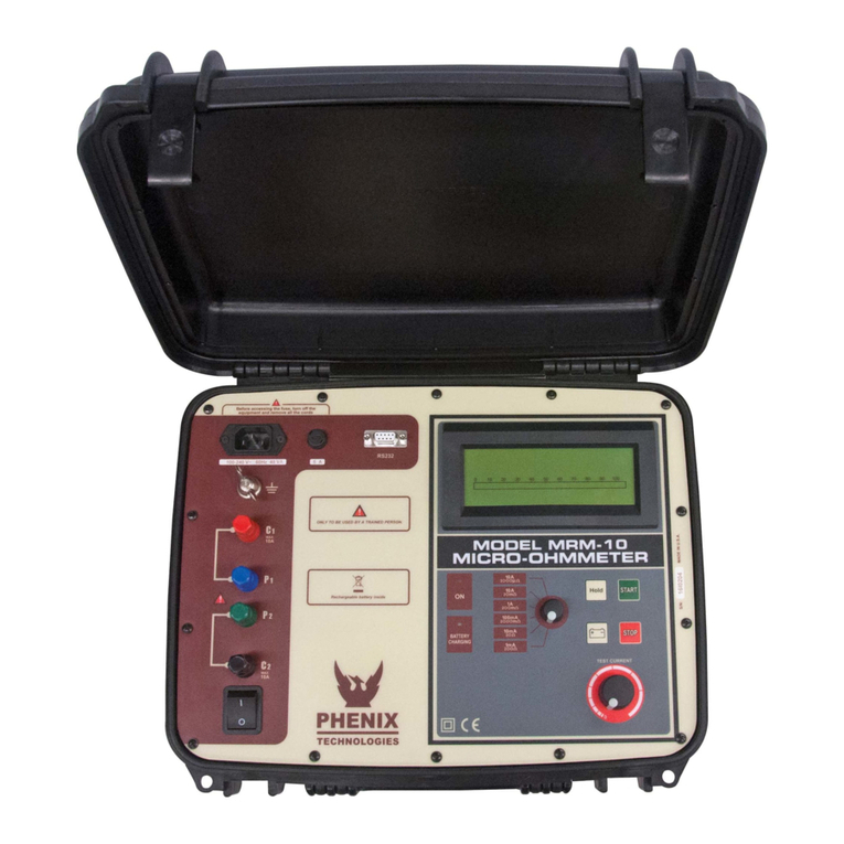
Phenix Technologies MRM-10 User manual

Phenix Technologies
Phenix Technologies MRM-100-V2 User manual

Phenix Technologies
Phenix Technologies MRM10E User manual

Phenix Technologies
Phenix Technologies MRM-100 User manual