Phenix 184804 User manual

INSTRUCTION MANUAL 15F21
SAVE THIS INSTRUCTIONS
184804
THIS PRODUCT CONTAINS A RECHARGEABLE LiFePO4 BATTERY.
THE BATTERY MUST BE RECYCLED OR DISPOSED OF PROPERLY.
WWW.PHENIXLIGHTING.COM
LiFePO4
IMPORTANT SAFEGUARDS
WHEN USING ELECTRICAL EQUIPMENT, BASIC SAFETY PRECAUTIONS SHOULD ALWAYS BE FOLLOWED, INCLUDING THE FOLLOWING
READ AND FOLLOW ALL SAFETY INSTRUCTIONS
1. To prevent electric shock, switch off the mains power supply until installation is complete and AC
input power is supplied to this product.
2. This product requires an unswitched AC power supply of 120-277V, 50/60Hz.
3. Make sure all connections are in accordance with the National or Canadian Electrical code and
any local regulations.
4. To reduce the risk of electrical shock, disconnect both normal power, emergency power supplies
and unit connector of this product before servicing.
5. For emergency operation of LED, incandescent, fluorescent fixtures and screw-base lamps.
6. Use this product in 0°C minimum, 50°C maximum ambient temperatures (Ta).
7. This product is suitable for use in dry or damp locations. Do not use outdoors. Do not mount
it near gas, heaters, air outlets or other hazardous locations.
8. Do not attempt to service the batteries. A sealed, non-maintenance battery is used that is not
field replaceable. Contact the manufacturer for information or service.
9. The use of accessory equipment not recommended by the manufacturer may cause an unsafe
condition and void warranty.
10. Do not use this product for other than intended use.
11. Installation and service should be performed by qualified service personnel.
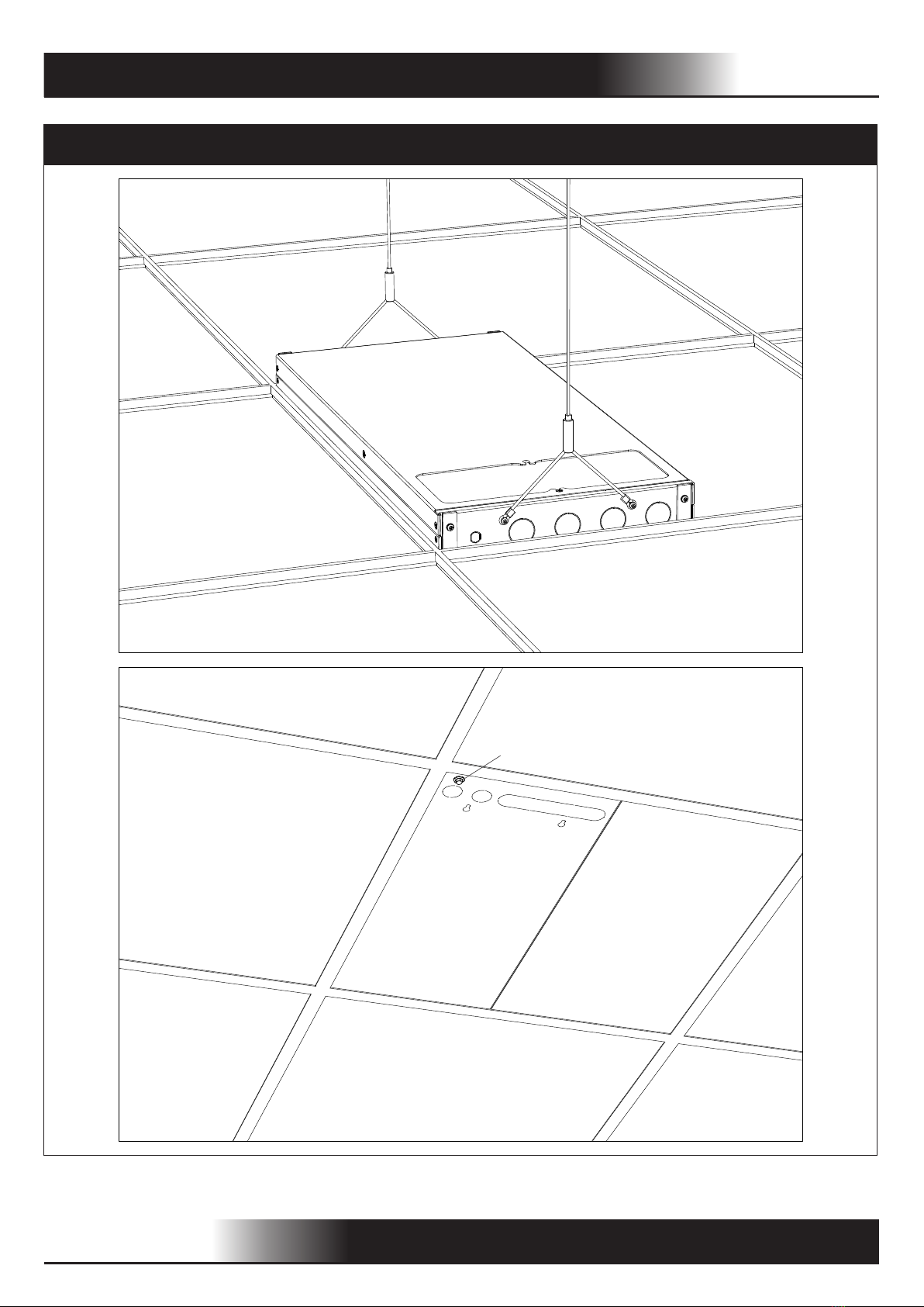
12. This product should be mounted in locations and at heights where it will not readily be subjected
to tampering by unauthorized personnel.
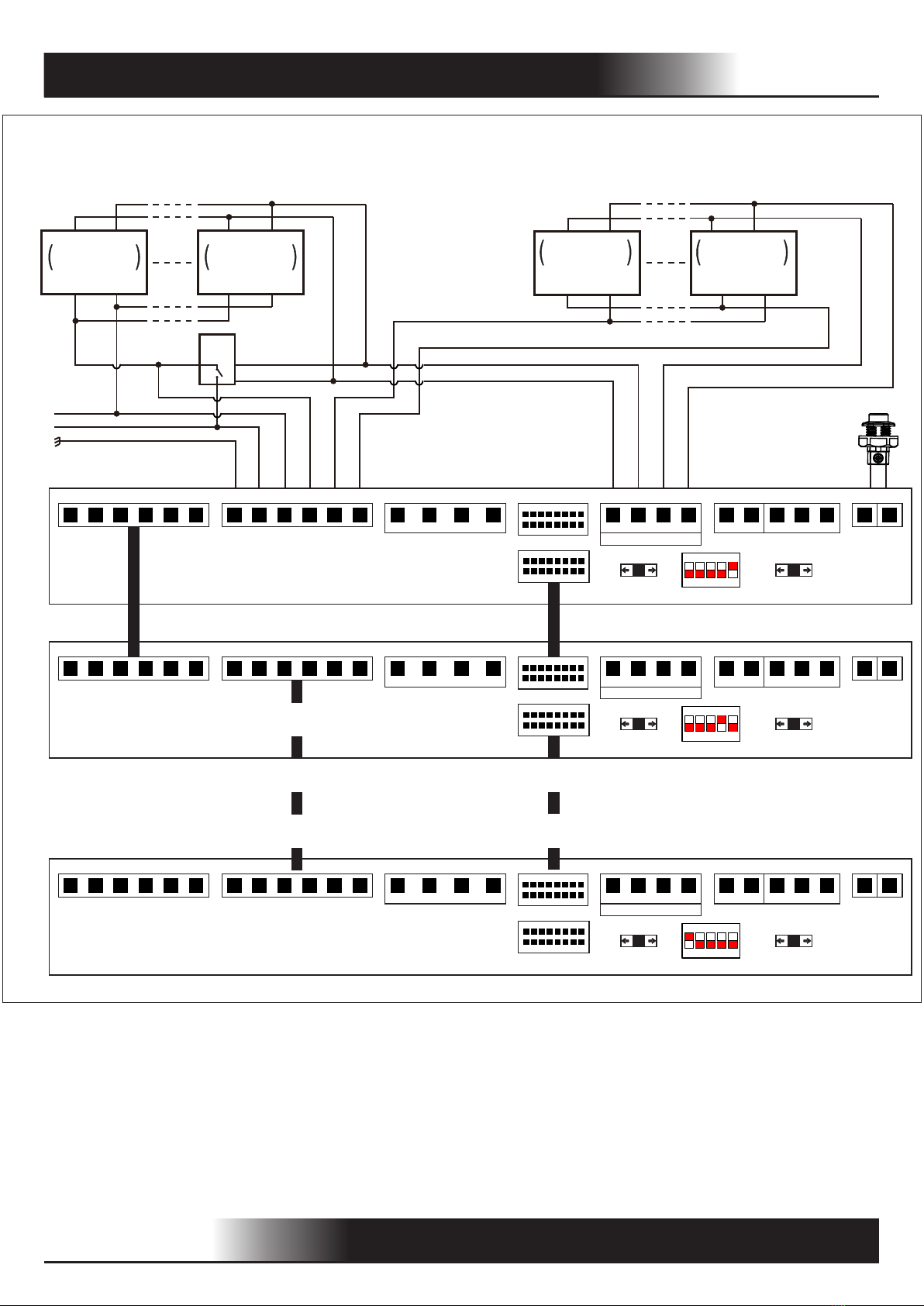
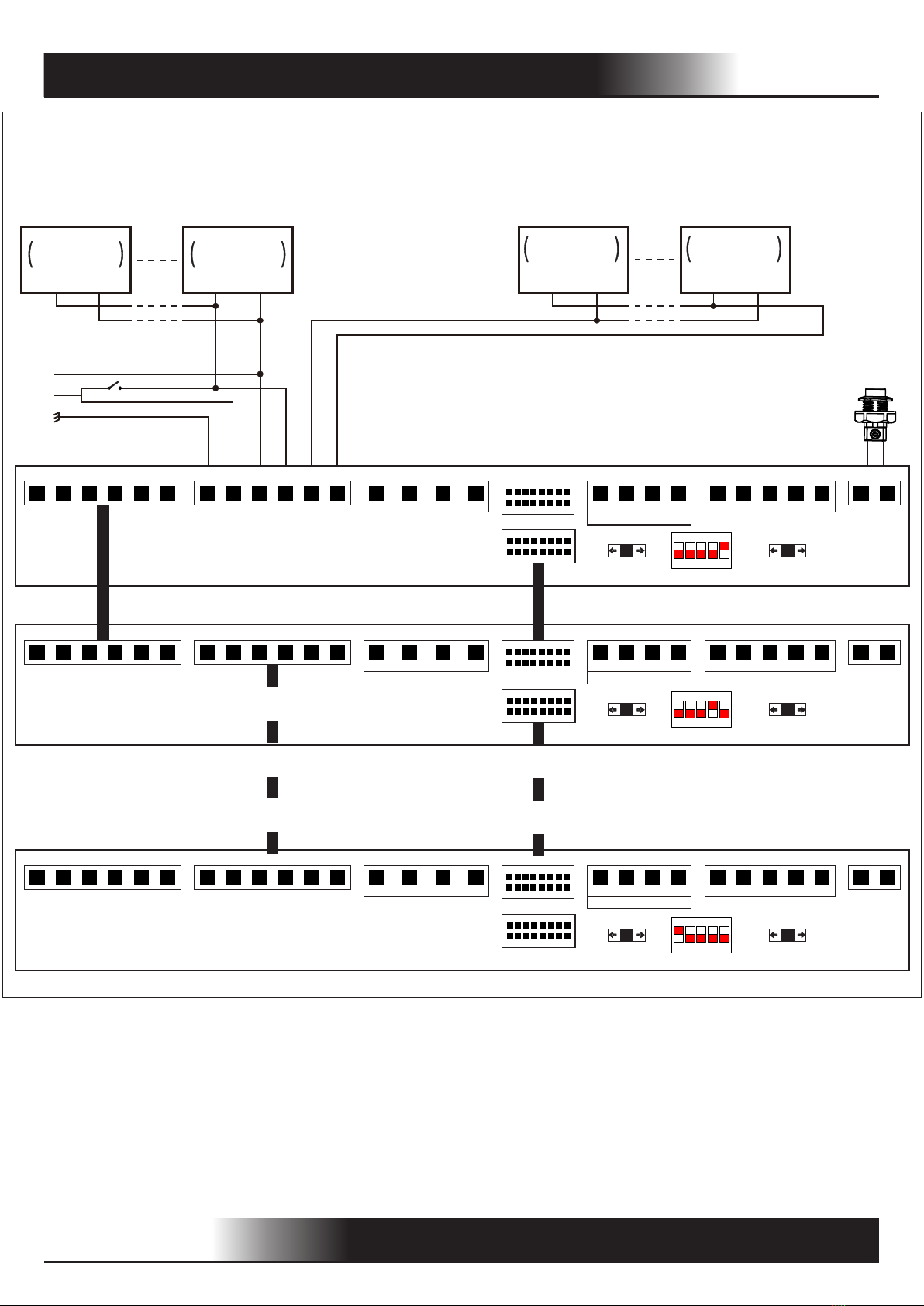
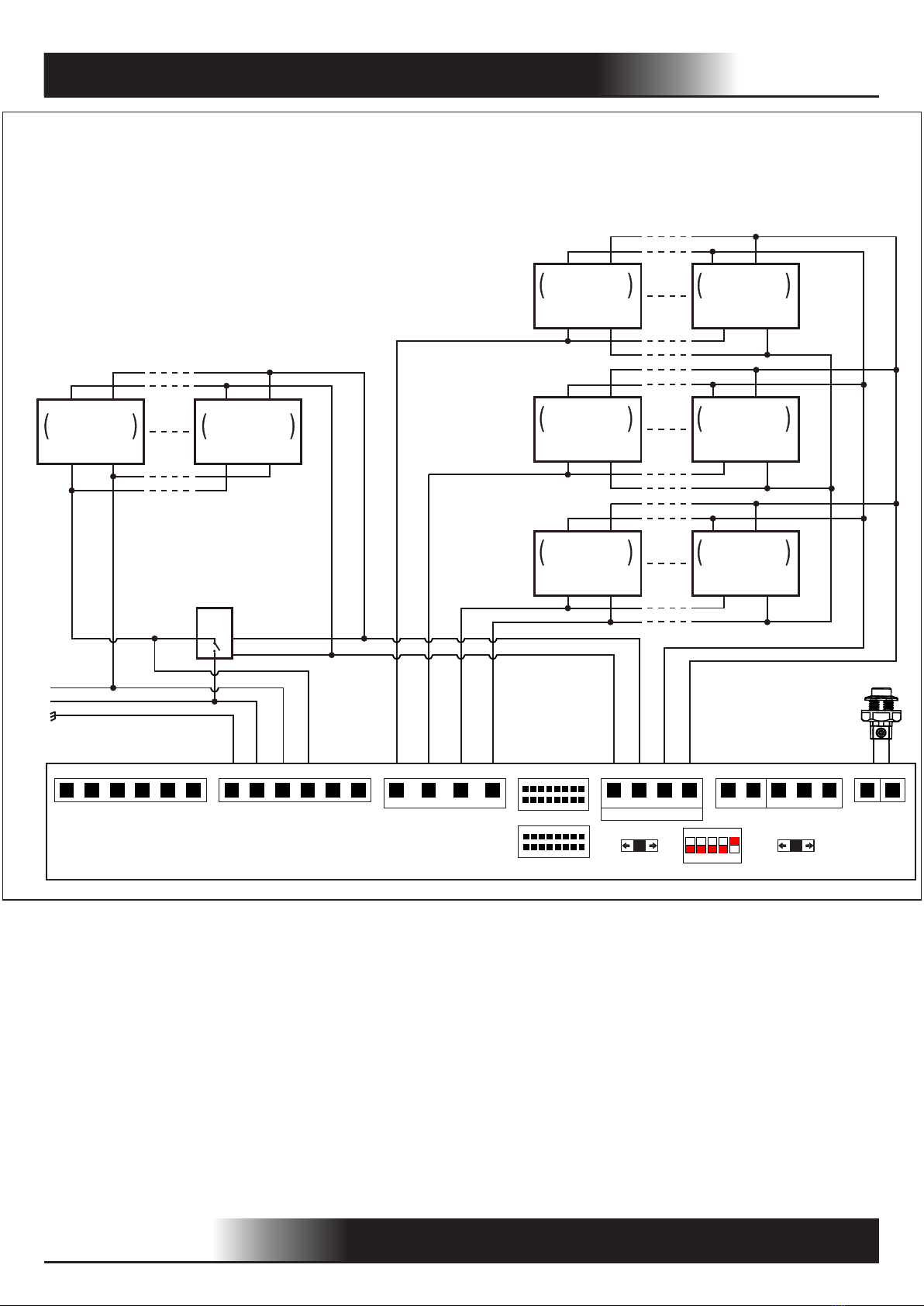
PURE SINUSOIDAL AC OUTPUT
OUTPUT VOLTAGE AUTO SETTING TO INPUT VOLTAGE
PATENTED APD TECHNOLOGY - AUTO PRESET DIMMING THE
CONNECTED LOAD IN EMERGENCY MODE
AUTO DIMMING (0-10V) OF CONNECTED LOAD UP TO 4000W
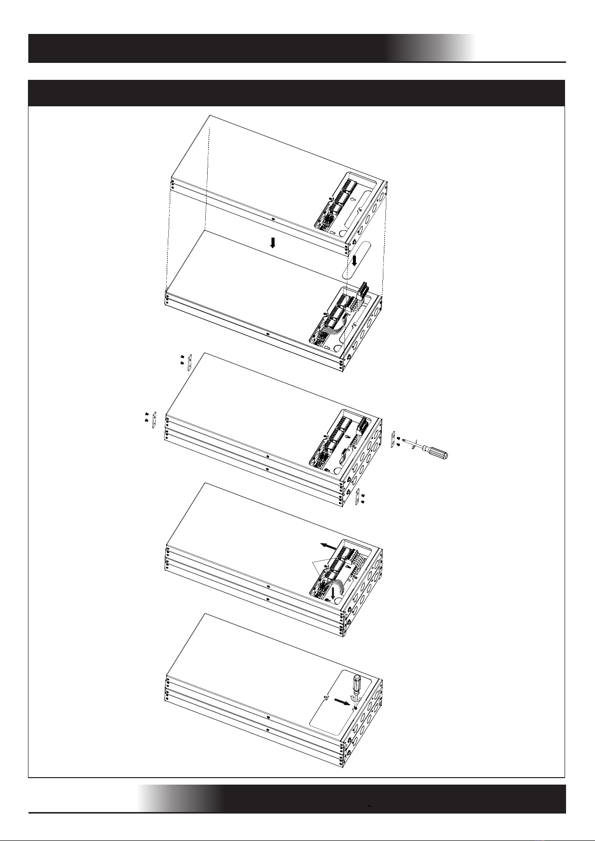
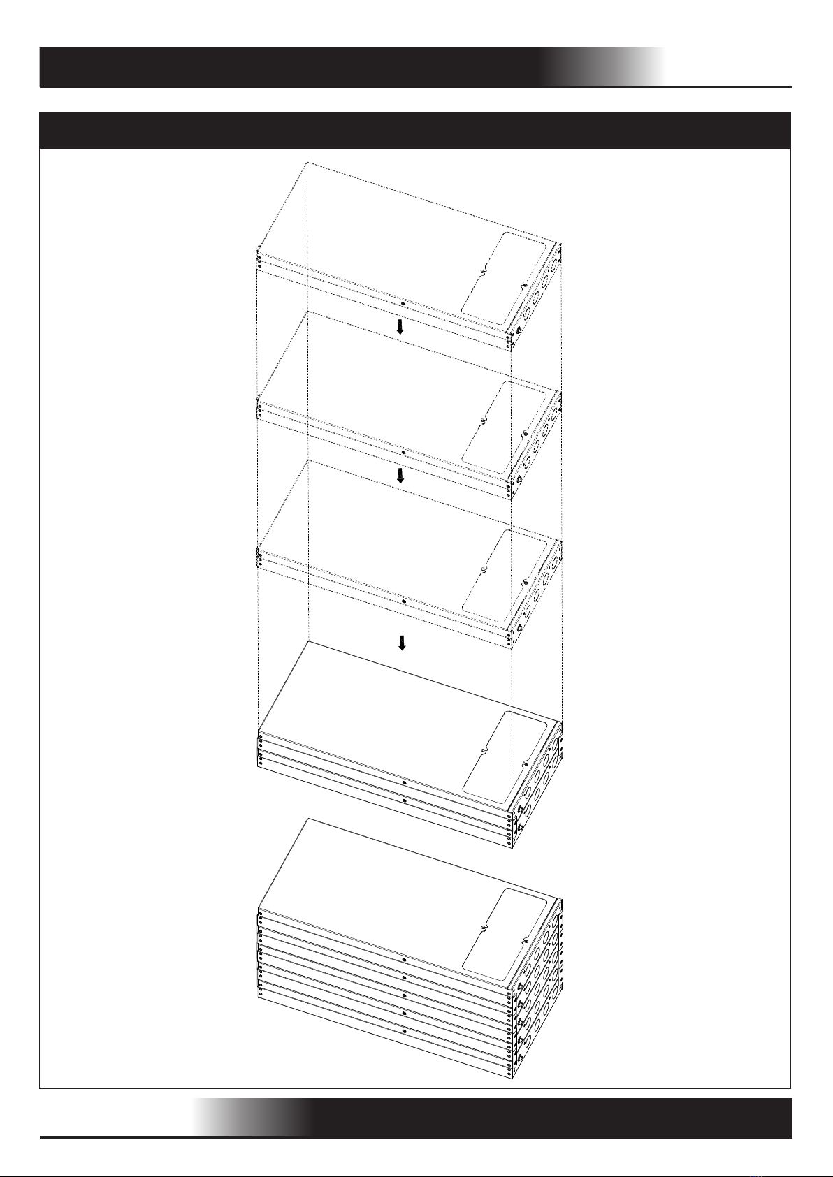
MODULAR DESIGN, FLEXIBLY PARALLELABLE COMBINATION FROM 1 TO 5 MODULES
PARALLELABLE MODULAR INVERTER

INSTALLATION
WWW.PHENIXLIGHTING.COM
INSIDE THE LUMINAIRE
CAUTION: MAKE CERTAIN THE AC POWER IS OFF AND THE BATTERY SWITCH IS OFF UNTIL
THE INSTALLATION IS COMPLETE.
1. SPECIFICATION OF 184804
2. INSTALLING THE 184804
2/14
SURFACE MOUNTING
Four 1-1/8" (Ø28.5mm) knock-out holes
Two 1-1/8" (Ø28.5mm)
knock-out holes
23
LED Test Switch
Output
Voltage
Input
230V/50Hz
120V/60Hz
230V/50Hz
120V/60Hz
277V/60Hz 277V/60Hz
800W
Max. Output power Quantity of 184804
4 (Parallelable)
3 (Parallelable)
1600W
5 (Parallelable)
2 (Parallelable)
1200W
2000W
400W 1 (Single)

INSIDE THE LUMINAIRE
CEILING GRID MOUNTING
INSTALLATION
WWW.PHENIXLIGHTING.COM 3/14
LED Test Switch

INSIDE THE LUMINAIRE
PARALLELABLE MOUNTING 1/3
INSTALLATION
WWW.PHENIXLIGHTING.COM 4/14
1
2
3
4

INSIDE THE LUMINAIRE
PARALLELABLE MOUNTING 2/3
INSTALLATION
WWW.PHENIXLIGHTING.COM 5/14
5
6
7
8
9
10
7
7
7

INSIDE THE LUMINAIRE
PARALLELABLE MOUNTING 3/3
INSTALLATION
WWW.PHENIXLIGHTING.COM 6/14
1
2
3
4
5
1
2
3
4
5

WWW.PHENIXLIGHTING.COM
WIRING
CAUTION: DO NOT SWITCH ON THE BATTERY SWITCH UNTIL INSTALLATION IS COMPLETE.
1. The 184804 requires an unswitched AC power supply of 120-277 volt, 50/60Hz.
2. Refer to the wiring diagrams below. Make connections in the following order.
3. Consult the factory for other wiring diagrams.
SINGLE 184804 FOR 0-10V DIMMABLE EMERGENCY LIGHTING SYSTEM
MAX. DIMMABLE LOAD = 2000W @ 120V
4000W @ 277V
SINGLE 184804 FOR NON-DIMMABLE EMERGENCY LIGHTING SYSTEM
MAX. LOAD = 400W
7/14
LED Test Switch
485
RS 232
RS
ON
Circuit Breaker (Optional)
OFF
0-10V DIMMER
ON
Dim in Dim out
Synchronous Port
GND
L L
NGND
L
N
L
+-+--+RX TX GND
L3 L 2 L 1
N-OUT L-OUT N-OUT
Unswitched Switched Unswitched Switched
485
RS 232
RS
-+
LED
FLUORESCENT
INCANDESCENT
LUMINAIRE
FOR EMERGENCY
LED
FLUORESCENT
INCANDESCENT
LUMINAIRE
FOR EMERGENCY
N-OUT L-OUT
NEUTRAL
GROUND
HOT
0-10V
DIMMER
120 -277 VAC
LED
FLUORESCENT
INCANDESCENT
LUMINAIRE
LED
FLUORESCENT
INCANDESCENT
LUMINAIRE
BATTERY SWITCH
LED Test Switch
485
RS 232
RS
ON
Circuit Breaker (Optional)
OFF
0-10V DIMMER
ON
Dim in Dim out
Synchronous Port
GND
L L
NGND
L
N
L
+-+--+RX TX GNDL3 L 2 L 1
N-OUT L-OUT N-OUT
Unswitched Switched Unswitched Switched
485
RS 232
RS
-+
LED
FLUORESCENT
INCANDESCENT
LUMINAIRE
FOR EMERGENCY
LED
FLUORESCENT
INCANDESCENT
LUMINAIRE
FOR EMERGENCY
N-OUT L-OUT
NEUTRAL
GROUND
HOT 120-277 VAC
Switch
LED
FLUORESCENT
INCANDESCENT
LUMINAIRE
LED
FLUORESCENT
INCANDESCENT
LUMINAIRE
BATTERY SWITCH
ANY QUANTITY
ANY QUANTITY

WWW.PHENIXLIGHTING.COM
WIRING
PARALLELABLE 184804 FOR 0-10V DIMMABLE EMERGENCY LIGHTING SYSTEM
8/14
4000W @ 277V
LED Test Switch
485
RS 232
RS
ON
Circuit Breaker (Optional)
OFF
0-10V DIMMER
ON
Dim in Dim out
Synchronous Port
GND
L L
NGND
L
N
L
+-+--+RX TX GNDL3 L 2 L 1
N-OUT L-OUT N-OUT
Unswitched Switched Unswitched Switched
485
RS 232
RS
-+
N-OUT L-OUT
LED Test Switch
485
RS 232
RS
ON
Circuit Breaker (Optional)
OFF
0-10V DIMMER
ON
Dim in Dim out
Synchronous Port
GND
L L
NGND
L
N
L
+-+--+RX TX GNDL3 L 2 L 1
N-OUT L-OUT N-OUT
Unswitched Switched Unswitched Switched
485
RS 232
RS
-+
N-OUT L-OUT
2
5
LED Test Switch
485
RS 232
RS
ON
Circuit Breaker (Optional)
OFF
0-10V DIMMER
ON
Dim in Dim out
Synchronous Port
GND
L L
NGND
L
N
L
+-+--+RX TX GNDL3 L 2 L 1
N-OUT L-OUT N-OUT
Unswitched Switched Unswitched Switched
485
RS 232
RS
-+
LED
FLUORESCENT
INCANDESCENT
LUMINAIRE
FOR EMERGENCY
LED
FLUORESCENT
INCANDESCENT
LUMINAIRE
FOR EMERGENCY
N-OUT L-OUT
NEUTRAL
GROUND
HOT
0-10V
DIMMER
120 -277 VAC
LED
FLUORESCENT
INCANDESCENT
LUMINAIRE
LED
FLUORESCENT
INCANDESCENT
LUMINAIRE
BATTERY SWITCH
BATTERY SWITCH
BATTERY SWITCH
1
MAX. DIMMABLE LOAD = 2000W @ 120V
ANY QUANTITY

WWW.PHENIXLIGHTING.COM
WIRING
PARALLELABLE 184804 FOR NON-DIMMABLE EMERGENCY LIGHTING SYSTEM
MAX. LOAD = 800W (2x184804)
=1200W (3x184804)
=1600W (4x184804)
=2000W (5x184804)
9/14
LED Test Switch
485
RS 232
RS
ON
Circuit Breaker (Optional)
OFF
0-10V DIMMER
ON
Dim in Dim out
Synchronous Port
GND
L L
NGND
L
N
L
+-+--+RX TX GNDL3 L 2 L 1
N-OUT L-OUT N-OUT
Unswitched Switched Unswitched Switched
485
RS 232
RS
-+
N-OUT L-OUT
LED Test Switch
485
RS 232
RS
ON
Circuit Breaker (Optional)
OFF
0-10V DIMMER
ON
Dim in Dim out
Synchronous Port
GND
L L
NGND
L
N
L
+-+--+RX TX GNDL3 L 2 L 1
N-OUT L-OUT N-OUT
Unswitched Switched Unswitched Switched
485
RS 232
RS
-+
N-OUT L-OUT
2
5
LED Test Switch
485
RS 232
RS
ON
Circuit Breaker (Optional)
OFF
0-10V DIMMER
ON
Dim in Dim out
Synchronous Port
GND
L L
NGND
L
N
L
+-+--+RX TX GNDL3 L 2 L 1
N-OUT L-OUT N-OUT
Unswitched Switched Unswitched Switched
485
RS 232
RS
-+
LED
FLUORESCENT
INCANDESCENT
LUMINAIRE
FOR EMERGENCY
LED
FLUORESCENT
INCANDESCENT
LUMINAIRE
FOR EMERGENCY
N-OUT L-OUT
NEUTRAL
GROUND
HOT 120-277 VAC
Switch
LED
FLUORESCENT
INCANDESCENT
LUMINAIRE
LED
FLUORESCENT
INCANDESCENT
LUMINAIRE
BATTERY SWITCH
BATTERY SWITCH
BATTERY SWITCH
1
ANY QUANTITY

WWW.PHENIXLIGHTING.COM
WIRING
SINGLE 184804 FOR 0-10V DIMMABLE EMERGENCY LIGHTING SYSTEM
(WITH 1,2 OR 3 CIRCUIT BREAKERS)
NEUTRAL
GROUND
HOT
LED
FLUORESCENT
INCANDESCENT
LUMINAIRE
FOR EMERGENCY
LED
FLUORESCENT
INCANDESCENT
LUMINAIRE
FOR EMERGENCY
LED
FLUORESCENT
INCANDESCENT
LUMINAIRE
FOR EMERGENCY
LED
FLUORESCENT
INCANDESCENT
LUMINAIRE
FOR EMERGENCY
LED
FLUORESCENT
INCANDESCENT
LUMINAIRE
FOR EMERGENCY
LED
FLUORESCENT
INCANDESCENT
LUMINAIRE
FOR EMERGENCY
0-10V
DIMMER
120 - 277 VAC
LED
FLUORESCENT
INCANDESCENT
LUMINAIRE
LED Test Switch
485
RS 232
RS
ON
Circuit Breaker
OFF
0-10V DIMMER
ON
Dim in Dim out
Synchronous Port
GND
L L
NGND
L
N
L
+-+--+RX TX GNDL3 L 2 L 1
N-OUT L-OUT N-OUT
Unswitched Switched Unswitched Switched
485
RS 232
RS
-+
N-OUT L-OUT
LED
FLUORESCENT
INCANDESCENT
LUMINAIRE
BATTERY SWITCH
10/14
4000W @ 277V
MAX. DIMMABLE LOAD = 2000W @ 120V
ANY QUANTITY

WWW.PHENIXLIGHTING.COM
WIRING
SINGLE 184804 FOR NON-DIMMABLE EMERGENCY LIGHTING SYSTEM
(WITH 1,2 OR 3 CIRCUIT BREAKERS)
MAX. LOAD=400W
LED
FLUORESCENT
INCANDESCENT
LUMINAIRE
FOR EMERGENCY
LED
FLUORESCENT
INCANDESCENT
LUMINAIRE
FOR EMERGENCY
LED
FLUORESCENT
INCANDESCENT
LUMINAIRE
FOR EMERGENCY
LED
FLUORESCENT
INCANDESCENT
LUMINAIRE
FOR EMERGENCY
LED
FLUORESCENT
INCANDESCENT
LUMINAIRE
FOR EMERGENCY
LED
FLUORESCENT
INCANDESCENT
LUMINAIRE
FOR EMERGENCY
LED Test Switch
485
RS 232
RS
ON
Circuit Breaker
OFF
0-10V DIMMER
ON
Dim in Dim out
Synchronous Port
GND
L L
NGND
L
N
L
+-+--+RX TX GNDL3 L 2 L 1
N-OUT L-OUT N-OUT
Unswitched Switched Unswitched Switched
485
RS 232
RS
-+
N-OUT L-OUT
NEUTRAL
GROUND
HOT 120-277 VAC
Switch
LED
FLUORESCENT
INCANDESCENT
LUMINAIRE
LED
FLUORESCENT
INCANDESCENT
LUMINAIRE
BATTERY SWITCH
11/14
ANY QUANTITY

WWW.PHENIXLIGHTING.COM
WIRING
PARALLELABLE 184804 FOR 0-10V DIMMABLE EMERGENCY LIGHTING SYSTEM
(WITH 1,2 OR 3 CIRCUIT BREAKERS) MAX. DIMMABLE LOAD = 2000W @ 120V
4000W @ 277V
12/14
LED Test Switch
485
RS 232
RS
ON
Circuit Breaker
OFF
0-10V DIMMER
ON
Dim in Dim out
Synchronous Port
GND
L L
NGND
L
N
L
+-+--+RX TX GNDL3 L 2 L 1
N-OUT L-OUT N-OUT
Unswitched Switched Unswitched Switched
485
RS 232
RS
-+
N-OUT L-OUT
LED Test Switch
485
RS 232
RS
ON
Circuit Breaker
OFF
0-10V DIMMER
ON
Dim in Dim out
Synchronous Port
GND
L L
NGND
L
N
L
+-+--+RX TX GNDL3 L 2 L 1
N-OUT L-OUT N-OUT
Unswitched Switched Unswitched Switched
485
RS 232
RS
-+
N-OUT L-OUT
2
5
NEUTRAL
GROUND
HOT
LED
FLUORESCENT
INCANDESCENT
LUMINAIRE
FOR EMERGENCY
LED
FLUORESCENT
INCANDESCENT
LUMINAIRE
FOR EMERGENCY
LED
FLUORESCENT
INCANDESCENT
LUMINAIRE
FOR EMERGENCY
LED
FLUORESCENT
INCANDESCENT
LUMINAIRE
FOR EMERGENCY
LED
FLUORESCENT
INCANDESCENT
LUMINAIRE
FOR EMERGENCY
LED
FLUORESCENT
INCANDESCENT
LUMINAIRE
FOR EMERGENCY
0-10V
DIMMER
120 -277 VAC
LED
FLUORESCENT
INCANDESCENT
LUMINAIRE
LED Test Switch
485
RS 232
RS
ON
Circuit Breaker
OFF
0-10V DIMMER
ON
Dim in Dim out
Synchronous Port
GND
L L
NGND
L
N
L
+-+--+RX TX GNDL3 L 2 L 1
N-OUT L-OUT N-OUT
Unswitched Switched Unswitched Switched
485
RS 232
RS
-+
N-OUT L-OUT
LED
FLUORESCENT
INCANDESCENT
LUMINAIRE
BATTERY SWITCH
BATTERY SWITCH
BATTERY SWITCH
1
ANY QUANTITY

WWW.PHENIXLIGHTING.COM
WIRING
PARALLELABLE 184804 FOR NON-DIMMABLE EMERGENCY LIGHTING SYSTEM
(WITH 1,2 OR 3 CIRCUIT BREAKERS)
LED Test Switch
485
RS 232
RS
ON
Circuit Breaker
OFF
0-10V DIMMER
ON
Dim in Dim out
Synchronous Port
GND
L L
NGND
L
N
L
+-+--+RX TX GNDL3 L 2 L 1
N-OUT L-OUT N-OUT
Unswitched Switched Unswitched Switched
485
RS 232
RS
-+
N-OUT L-OUT
LED Test Switch
485
RS 232
RS
ON
Circuit Breaker
OFF
0-10V DIMMER
ON
Dim in Dim out
Synchronous Port
GND
L L
NGND
L
N
L
+-+--+RX TX GNDL3 L 2 L 1
N-OUT L-OUT N-OUT
Unswitched Switched Unswitched Switched
485
RS 232
RS
-+
N-OUT L-OUT
2
5
LED
FLUORESCENT
INCANDESCENT
LUMINAIRE
FOR EMERGENCY
LED
FLUORESCENT
INCANDESCENT
LUMINAIRE
FOR EMERGENCY
LED
FLUORESCENT
INCANDESCENT
LUMINAIRE
FOR EMERGENCY
LED
FLUORESCENT
INCANDESCENT
LUMINAIRE
FOR EMERGENCY
LED
FLUORESCENT
INCANDESCENT
LUMINAIRE
FOR EMERGENCY
LED
FLUORESCENT
INCANDESCENT
LUMINAIRE
FOR EMERGENCY
LED Test Switch
485
RS 232
RS
ON
Circuit Breaker
OFF
0-10V DIMMER
ON
Dim in Dim out
Synchronous Port
GND
L L
NGND
L
N
L
+-+--+RX TX GNDL3 L 2 L 1
N-OUT L-OUT N-OUT
Unswitched Switched Unswitched Switched
485
RS 232
RS
-+
N-OUT L-OUT
NEUTRAL
GROUND
HOT 120-277 VAC
Switch
LED
FLUORESCENT
INCANDESCENT
LUMINAIRE
LED
FLUORESCENT
INCANDESCENT
LUMINAIRE
BATTERY SWITCH
BATTERY SWITCH
BATTERY SWITCH
1
13/14
ANY QUANTITY
MAX. LOAD = 800W (2x184804)
=1200W (3x184804)
=1600W (4x184804)
=2000W (5x184804)

WWW.PHENIXLIGHTING.COM
OPERATION / TESTING / MAINTENANCE
OPERATION
When AC power is applied, the LED test switch is illuminated, indicating that the batteries are being charged.
When AC power fails, the 184804 automatically switches to emergency power, operating the lighting load at
rated emergency power. During power failure, the LED test switch will be off. When the AC power is restored,
the 184804 switches the system back to normal mode of operation and resumes battery charging.
The minimum emergency operation time is 90 minutes. A short term discharge test may be conducted after
the 184804 has been charging for 1 hour. Charge for 24 hours before conducting a long term discharge test.
TESTING AND MAINTENANCE
The following Periodic testing is recommended to ensure the system is working correctly.
1. Visually inspect the LED test switch (LTS) monthly. It should be illuminated when AC power is applied.
2. Conduct a 30-second discharge test by switching off the emergency breaker every month. The LTS will be
off.
3. Conduct a 90-minute discharge test once per year. The LTS will be off during the test.
AUTO TEST
The 184804 has an Auto Test feature which saves cost by reducing the need for manual testing.
1. Initial Auto Test
When the system is connected properly and powered on (make sure the load is switched on), the 184804 will
perform an Initial Auto Test. If any abnormal conditions exist, the LTS will blink quickly. Once the abnormal
condition is corrected, the LTS will function correctly. The Initial Auto Test will be restarted automatically
when the connected dimmable loads' maximum power increases.
2. Preprogrammed Scheduled Auto Test
a) The unit will conduct the first Monthly Auto Test after 24 hours and up to 7 days after initial power on. Then
monthly tests will be performed every 30 days.
b) Annual Auto test will occur every 52 weeks after initial power on.
- Monthly Auto Test
The Monthly Auto Test shall be executed every 30 days, and will test:
Normal to emergency transfer function, emergency, charging and discharging conditions are normal. Monthly
test time is approximately 60 seconds.
- Annual Auto Test
Annual Auto Test will occur every 52 weeks after the initial 24 hours full charge, and will test:
Proper initial battery voltage, 90-minute emergency operation and acceptable battery voltage at the end of
the full 90-minute test.
If the Auto Test is interrupted by a power failure, a full 90-minute Auto Test will occur again 24 hours after the
power is restored. If the power failure causes the battery to fully discharge, the product will restart the Initial
Auto Test and Preprogrammed Scheduled Auto Test.
MANUAL TEST
1. Press the LTS one time to simulate emergency mode for 10 seconds.
2. Press the LTS 2 times continuously within 5 seconds to force a 60-second monthly test. After the test is
completed, the next (30-day) monthly test will count from this date.
3. Press the LTS 3 times continuously within 5 seconds to force a 90-minute annual test. After the test is
completed, the next (52-week) annual test will count from this date.
4. In normal mode, press and hold the LTS for greater than 3 seconds to restart Initial Auto Test.
5. During any manual test, press and hold the LTS for greater than 3 seconds to terminate a manual test.
The Preprogrammed Scheduled Auto Test time will not change.
LED TEST SWITCH CONDITIONS
LTS Slow Blinking: Normal Charging
LTS On: Battery Fully Charged - Normal Condition
LTS Off: Power Failure
LTS Gradual Change: In Testing Mode
LTS Quickly Blinking: Abnormal Condition - Corrective Action Required
14/14
Table of contents
Other Phenix Lighting Equipment manuals
Popular Lighting Equipment manuals by other brands

JB Systems
JB Systems iMove 7S Operation manual

BARRON
BARRON EXITRONIX ILX Series installation instructions

Samsung
Samsung BP81-00631A-00 Quick setup guide

EuroLite
EuroLite Outdoor Neon Stick user manual

Greenice
Greenice BALIZAS LED Y FOCOS DE JARDIN instruction manual

EuroLite
EuroLite DM-250 Lighting-Effect user manual