®
6
®
7
Operating Instructions
Set Up
Operation
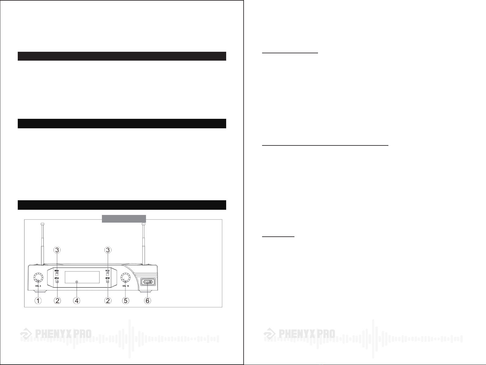
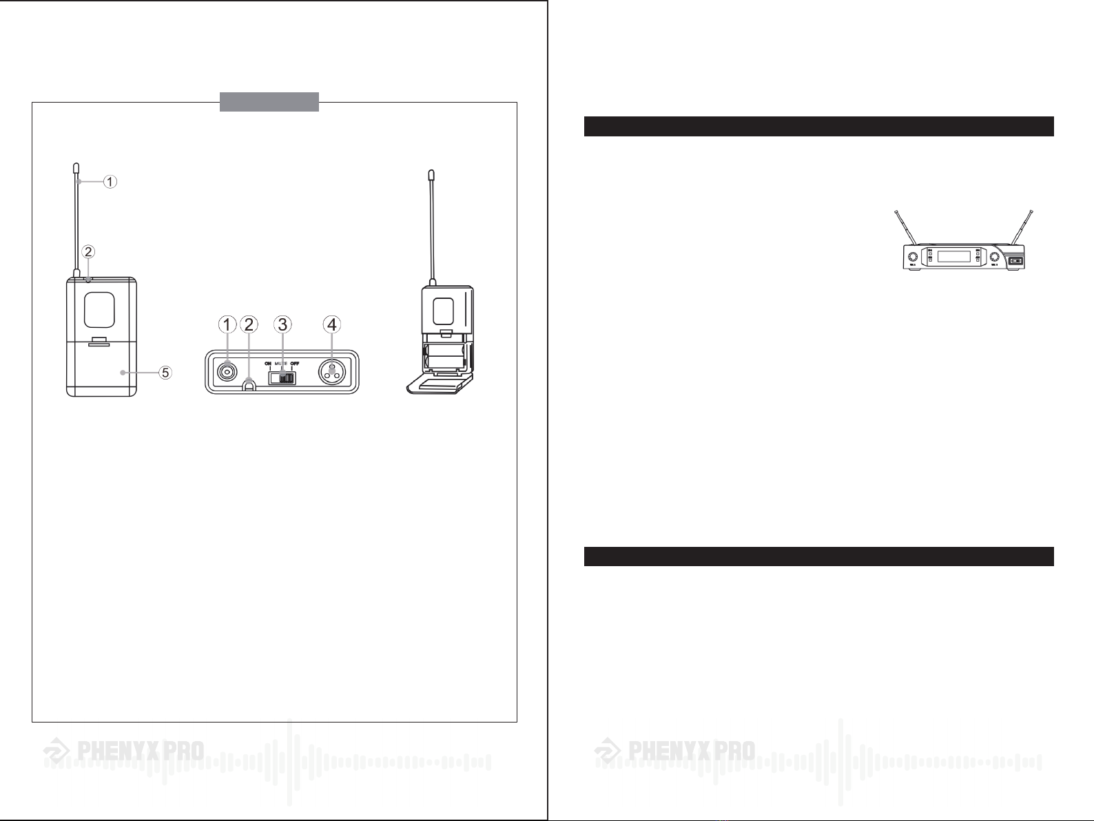
①Antenna
②Battery Power Indicator
③ON/MUTE/OFF switch
④Microphone input
⑤Battery compartment
Side View Top View With battery com-
partment open
Bodypack
The Phenyx VHF bodypack is to be used with the Phenyx
lavalier microphones & headsets
Set Up:
1 - Secure the bodypack to clothing, belt or pocket.
2 - (a) For a lavalier microphone, clip the microphone to clothing about 1 foot under the mouth.
(b) For a headset, install headset comfortably on head so the microphone can be placed
close to the mouth.
3 - Connect the microphone audio connector to the bodypack microphone input (4)
4 - Turn the bodypack on by sliding the the ON/MUTE/OFF switch to the "ON" position. The
battery power indicator (2) will light up briefly, indicating that the batteries have sufficient
power.
If the battery power indicator (3) stays continuously on after powering on the
bodypack, the batteries must be replaced. To replace the batteries, proceed as follows:
- Open the battery compartment door by pushing on the door sides and pulling it open
- After removing the old batteries, insert new ones, making sure to respect
proper polarity
- Close compartment by gently pushing the compartment door until it clicks
1 - Install fresh batteries in the transmitters (refer to the section relative to the sp-
ecific transmitter you are using).
2 - Connect the AC power adapter to a wall outlet and to the back of the receiver.
3 - Position the antennas 60° apart from each other
as shown.
4 - Connect one of the two outputs available at the back panel to the next stage
in your system. Typically, use the 4" output to connect to unbalanced equipm-
ent such as consumer level receivers, amplifiers, and mixers. Connect to pro-
fessional equipment using the XLR output (cable not included).
5 - Making sure the volume of your speakers is off, turn on the receiver and the
transmitters. The "RF" LED turns on, indicating that the corresponding trans-
mitter is paired with the receiver. Note that the number displayed (the channel
number) is fixed and cannot be adjusted. The "AF" LED indicates the presence
of an audio signal coming from the transmitter.
6 - Turn the volume of your speakers back on and start increasing the volume of
the transmitters until proper volume is achieved. The balance between the two
microphones can be adjusted with the front panel volume controls.
For better results, keep the transmitters at least 2' away from the receiver but
within the transmitter's range (150'). Keep the transmitters in a direct line of
sight with the receiver whenever possible.
Transmitters can be used one at a time or simultaneously.
Use the MUTE position on the transmitter switch to silence the microphone
without interrupting the pairing with the receiver, which could cause unwanted
popping sounds.