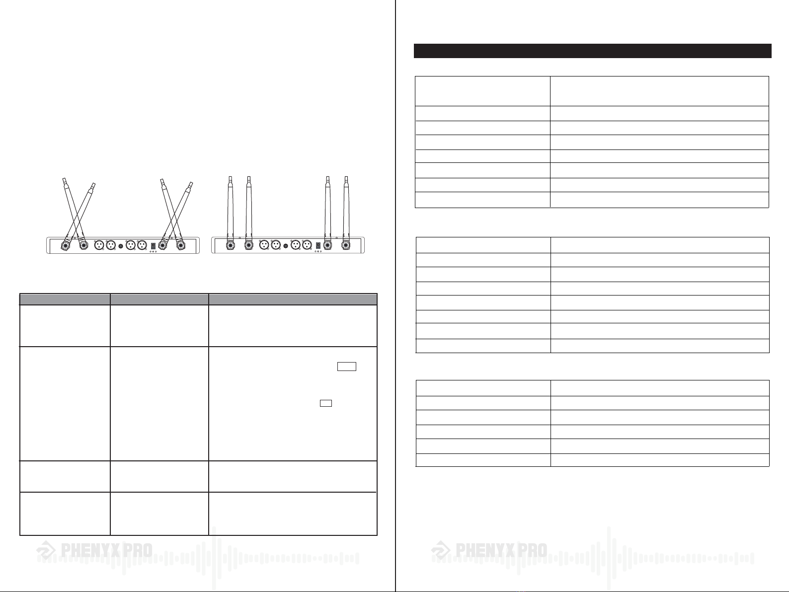
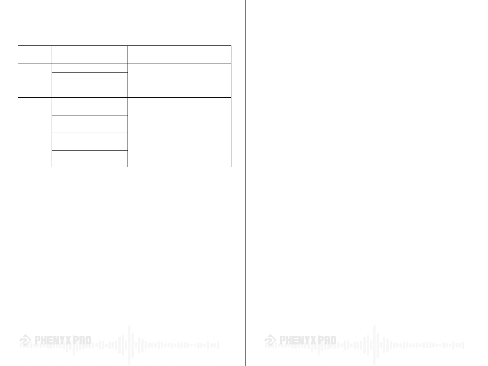
PHENYX PRO PTU-71 Series User manual

www.phenyxpro.com
®
OWNER’S MANUAL
PTU-71/7000/6000 Series
Selectable UHF Frequency
Dual / Quad / Eight Channels Wireless Microphone System

® ®
43
Thank you for purchasing the Phenyx Pro PTU-71/7000/6000 Series.
For the best results and the utmost satisfaction for your new unit,
please read this manual carefully to ensure proper operation,
and keep it for future reference. For more information,
please visit our store: www.phennyxpro.com
Table of Contents
System Description...............................................................................................................................4
System overview.................................................................................................................................4
System Features................................................................................................................................4
System components.......................................................................................................................... 4
Functions of Parts................................................................................................................................5
Receiver..............................................................................................................................................5
Transmitters.........................................................................................................................................7
Operation Guidance..............................................................................................................................8
Single system setup............................................................................................................................8
Multiple system setup........................................................................................................................10
Wireless Tips.......................................................................................................................................11
Troubleshooting..................................................................................................................................12
Specification.......................................................................................................................................13
Technical Support & Warranty Information.......................................................................................14
Your system comes with a combination of the following components.
PWR-71
PWR-7000
PWR-6000
Dual-channel Wireless Receiver
Quad-channel Wireless Receiver
Eight-channel Wireless Receiver
System Description
System overview
System features
System components
Receiver Accessories
The PTU-71/7000/6000 Series was born with the mission that everyone can enjoy superior sound
quality and professional features without overpaying. Adjustable UHF frequency design provides
more flexibility when facing outside interference. The state-of-the-art AutoScan circuitry scans the
entire RF environment precisely to quickly locate the best available frequency and deliver promising
wireless performance. Guarantee fewer cutoffs and dropouts for your important moments in live
shows, weddings, church, DJs, conference meetings, public speaking, etc.
• Adjustable UHF frequency groups for multiset operation. The PTU-71 features 2x100 adjustable
frequencies, while the PTU-7000 features 4x40 and the PTU-6000 features 8x40.
• The IR synchronization enables you to pair up and operate painlessly.
• The auto-scan function serves as the automatic frequency management by precisely scanning
the entire RF environment and locating the best available frequency for interference-free and
dropout-free use.
• The advanced circuitry provides up to 328ft/100m long-range and rock-firm coverage
• Dynamic cartridge with a cardioid polar pattern flawlessly captures and smoothly transmits your
sound noise-freely.
• It escalates your voice to the next level and reproduces the lush, warm, natural, and flawless
sound.
• Two types of transmitters and various accessories provide easy customization.
PWH-7
PWB-7
Handheld Transmitter
Bodypack Transmitter
Transmitters
PHM-01-BLK
PHM-01-BGE
PLM-01-BLK
PLM-01-BGE
ANTB-500
PTA-01
PTA-02
Black Headset Mic
Beige Headset Mic
Black Lapel Mic
Beige Lapel Mic
Antennas for 500 UHF Band
Power Adapter
1/4” Audio Cable
AA Batteries
Anti-rolling Rings
6.35MM to 3.5MM Adapter
User’s Manual

®
5
®
6
Functions of Parts
Receiver
PWR-71
POWER
VOL.A
ANT.B ANT.A
12~15V
150mA
MIX OUT BALANCED B BALANCED A
WIRELESS MICROPHONE SYSTEM
WIRELESS MICROPHONE SYSTEMWIRELESS MICROPHONE SYSTEM
WIRELESS MICROPHONE SYSTEM
▲
SET
▼
▲
SET
▼
- +
VOL.B
PTU-71
- +
IR
MHz
(( ANT ))
G.
CH
X
X X
XX
X
—
—
+
—
①
①
①
②
⑦
⑧
⑧
⑨
⑨
⑩
⑪
⑪
⑪
③
③
②
②
④
④
⑤
⑤
③
④
⑤
③
④
⑤
⑦
⑥
⑥
⑥⑦
⑧
⑨
⑩
⑩
PWR-7000
ANT.4
12~15V
150mA
MIX OUT
AF OUTPUT
BALANCED 4
AF OUTPUT
BALANCED 3
AF OUTPUT
BALANCED 2
AF OUTPUT
BALANCED 1
ANT.3 ANT.2 ANT.1
X
X X
X
—
—
+
—
X
X
X
X
X
X
POWER VOL.2
▲
SET
▼
▲
SET
▼- +
VOL.3
- +
VOL.4
- +
VOL.1
PTU-7000
- +
IR
▲
SET
▼
▲
SET
▼
IR
②
PWR-6000
DC INPUT
12-16V=500mA
MIX OUT
AF OUTPUT
BALANCED 8
AF OUTPUT
BALANCED 7
AF OUTPUT
BALANCED 6
AF OUTPUT
BALANCED 5
AF OUTPUT
BALANCED 4
AF OUTPUT
BALANCED 3
AF OUTPUT
BALANCED 2
AF OUTPUT
BALANCED 1
ANT.CANT.D
X
X
—
—
+
—
X
X X
X
ANT.AANT.B
X
X
X
X
X
X
X
X
X
X
X
X
①
POWER
VOL.3
▲
SET
▼
▲
SET
▼
- +
VOL.4
- +
VOL.5
- +
VOL.6
- +
VOL.7
- +
VOL.8
- +
VOL.1
PTU-6000
- +
VOL.2
- +
IR
▲
SET
▼
▲
SET
▼
IR
① Power button: Powers the unit on and off. When it is on, it lights green.
② Volume control knobs: Twist these knobs clockwise/counterclockwise to increase/decrease the volume.
*NOTE: Please check the corresponding name of each knob before adjusting the volume for the desired
channel properly.
③ Up button: Short press (tap) this button for frequency increment. Long press for 2 seconds to initiate
the lock function.
*NOTE: For PWR-6000, short press (tap) this button also for channel selection.
④ SET button: Short press (tap) this button for infrared synchronization setup. Long press for 2 seconds
to initiate the auto-scan function.
⑤ Down button: Short press (tap) this button for frequency decrement.
*NOTE: For PWR-6000, short press (tap) this button also for channel selection.
⑥LCD display
⑦ IR window: For infrared synchronization setup.
*NOTE: Please short press (tap) the SET button to start (LCD shows “F----”). Then vertically aim the IR window of
the transmitter to that of the receiver for pairing them up.
⑧ Antennas: For connecting detachable antennas and picking up signals from transmitters.
*NOTE: The PWR-71 has two antennas, while the PWR-7000 and PWR-6000, respectively, have four.
⑨ 1/4” mixed output jack: The 1/4” (6.35mm) output jack accepts an unbalanced TS phone-type
connector.
⑩ XLR audio output jack: The XLR audio output jacks accept a balanced XLR connector. Each
channel has its corresponding XLR output jack.
⑪ Power jack
Receiver display
① Group number
② Channel number
③ RF signal indicator: It appears when the transmitter is successfully
paired up with the receiver. When it disappears, the channel of
the receiver receives no signal.
④ Audio signal indicator: Ind icates audio signal level. “ ANT ” indicates
no audio signal. “ (
(
(ANT ))) ” indicates the highest audio signal level.
⑤ Frequency number

®
7
®
8
Operation Guidance
Transmitters Single system setup
Transmitter display
①Antenna
②Battery light: It maintains green to indicate the battery of the bodypack transmitter is sufficient.
It turns red to indicate the battery is low.
③ ON/MUTE/OFF power button: Long press the power button for 2 seconds to turn the transmitter
on/off. Short press (tap) to mute the transmitter.
④ 3-pin XLR jack
⑤ IR window: For infrared synchronization setup.
*NOTE: Please vertically aim the IR window of the transmitter to that of the receiver for pairing them up.
⑥ Battery compartment: Install batteries with the correct polarity.
① Group number
② Channel number
③ Mute indicator: The mute icon appears on the screen to
indicate the transmitter is muted.
④ Battery indicator: To indicate the real-time battery status.
Step 1: Connect and power up the receiver
① Connect antennas to the receiver via ANT jacks.
② Connect the power supply to the receiver via the power jack.
③ Connect the audio output to an amplifier/speaker or mixer via 1/4” mixed output jack or XLR
audio output jack.
④ Long press (2s)the receiver power button to turn it on.
Step 2: Turn on transmitters
① Install fresh batteries with the correct polarity.
② Long press power buttons to turn on transmitters.
*NOTE: The LCD screens of handheld and bodypack transmitters turn dim in standby mode. The LED light
on top of the bodypack transmitter remains green to indicate it is turned on.
Bodypack transmitter
PWB-7 PWH-7
Handheld transmitter
GROOP CHANNEL
ANT.4
12~15V
150mA
MIX OUT
AF OUTPUT
BALANCED 4
AF OUTPUT
BALANCED 3
AF OUTPUT
BALANCED 2
AF OUTPUT
BALANCED 1
ANT.3 ANT.2 ANT.1
X
X X
X
—
—
+
—
X
X
X
X
X
XPOWER
ON
ON
ON
①
①
② ③ ④
③
③ ④
⑤
⑥
⑥
⑤

®
9
®
10
Multiple system setup
Step 3: Manual setup
Short press (tap) the “▲”up and “▼”down
buttons to select the desired frequency.
*NOTE: For PWR-6000, press the “▲” up and
“▼” down buttons to select the desired channel
first. The selected channel will flash, and please
press SET to confirm. Then follow the step above.
Step 4: Pair up the receiver and transmitters
①One short press of the SET button again to initiate the IR synchronization.
② Vertically aim the IR window of a transmitter to that of the receiver.
*NOTE: The signal indicator “ ANT ” indicates the frequency is successfully synchronized. The audio
indicator “ (
(
(ANT )))” flashes to indicate the frequency is receiving audio signals.
VERTICALLY
VERTICALLY
The receiver is scanning
the best frequency.
Select and confirm the channel
first, and then scan the frequency.
“L ON ” for locking in,
and “L OF” for locking off
The best frequency
is found.
*NOTE
AutoScan setup
*NOTE
Step 3: AutoScan setup
① Long press (2s) the SET button of the receiver
to initiate the auto-scan function, which searches
for the best frequency in the RF environment.
② Wait until the new frequency appears on the screen.
*NOTE: For PWR-6000, press the “▲” up and “▼” down
buttons to select the desired channel first. The selected
channel will flash, and please press SET to confirm. Then
follow the steps above.
Long press the “▲” up button of the receiver for two seconds to lock your settings and to avoid a
ccidental touch.
*NOTE: For PWR-6000, press the “ ▲ ” up and “ ▼ ”down buttons to select the desired
channel first. The selected channel will flash, and please press SET to confirm. Then follow the step above.
You are suggested to use no more than 20 transmitters simultaneously(band and RF environment
depend).
Turn on any other equipment that could cause interference during the performance so it will
be detected during the group and channel scans in the following steps.
Before you begin system set up, turn all receivers ON and all transmitters OFF.
① Initiate the auto-scan function for a channel of a receiver.
② Turn on the first transmitter and pair it up with the receiver.
③ Repeat the above two steps until set up all channels.
④ Leave transmitters on and continue with additional systems according to the above three steps.
Optional step: Initiate the lock function
▲
SET
▼
2s
▲
SET
▼
2s ▲
SET
▼
▲
SET
▼
MHz
G.
CH
G.
CH
▲
SET
▼
2s
▲
SET
▼
MHz
G.
CH G.
CH
▲
SET
▼
▲
SET
▼
IR
PWR-6000
Select the channel first,
and then lock your settings.
*NOTE
▲
SET
▼
▲
SET
▼
IR
PWR-6000
▲
SET
▼
IR
MHz
G.
CH
▲
SET
▼
IR
MHz
G.
CH
ANT
(((
(
(
(

®
11
®
12
Wireless Tips
Specification
If you encounter wireless interference or dropouts, try the following suggestions:
• Replace the transmitter batteries.
• Choose a different frequency channel.
• Avoid approaching the receiver and transmitters with metal or other dense materials.
• Place the receiver as high as possible on the equipment rack.
• Remove any devices causing possible signal interference, such as cellphones, computers, media
players, two-way radios, and digital signal processors.
• Keep transmitters more than 6 feet (two meters) apart.
• Mark trouble spots during soundcheck and inform performers to avoid those areas.
• Place antennas away from each other.
ANT.4
12~15V
150mA
MIX OUT
AF OUTPUT
BALANCED 4
AF OUTPUT
BALANCED 3
AF OUTPUT
BALANCED 2
AF OUTPUT
BALANCED 1
ANT.3 ANT.2 ANT.1
X
X X
X
—
—
+
—
X
X
X
X
X
X
ANT.4
12~15V
150mA
MIX OUT
AF OUTPUT
BALANCED 4
AF OUTPUT
BALANCED 3
AF OUTPUT
BALANCED 2
AF OUTPUT
BALANCED 1
ANT.3 ANT.2 ANT.1
X
X X
X
—
—
+
—
X
X
X
X
X
X
X√
Troubleshooting
Specification
ISSUE INDICATOR STATUS CORRESPONDING SOLUTION
No sound or fain sound
Low battery
A howling noise
(also “feedback”) from
the speaker
Receiver LCD screen off
Receiver LCD screen on
The battery indicator shows
low battery status
• Replace fresh batteries for the transmitter.
• Do not point the microphone directly to the
speaker. And increase their distance.
• Make sure the transmitter is successfully paired
up with the receiver. You can see “ ANT ” on
the receiver screen.
• Make sure the transmitter successfully transmits
audio signals. You can see “ (
(
(ANT ))) ” flashes
on the receiver screen. Otherwise, replace
batteries for the transmitter. If it does not work,
replace the transmitter. Adjust volume controls
of the receiver and speaker to propel levels.
• Make sure the DC adapter is securely plugged
into an electrical outlet.
• Make sure the receiver is powered on.
• Overall System
Carrier frequency range
(Depends on local regulations)
Frequency Stability
Dynamic Range
Frequency response
Audio Output Level
Working distance
XLR Interface
Operafing temperature
UHF 530 - 580 MHz
0.003%
>105dB
50Hz-18kHz
1/4” inferface: 0-500mV; XLR interface: 0-500mV
100m/328ft
0-500mV
-10℃~+50℃
• Receiver
Output impedance
RF sensitivity
Image rejection
Spurious rejecfion
Power
Power requirement
Dimension
Weight
XLR connector: 200Ω
-105dBm
>110dB
>90dB
5W
DC 12- 15V, Current: 300mA, Extemal power adaptor
210mm × 160mm ×45mm
775g (27.3oz)
• Handheld & Bodypack Transmitter
Modulafion Mode
Maximum Deviation
Handheld Dimension
Handheld Weight
Power Requirement
Battery Life
FM
75kHz
249mm ×51 mm (9.8 × 2 in)
306g (10.8oz) (without batteries)
2 AA alkaline batteries (for each transmitter)
At least 8 hours with original batteries included

®
13
®
14
• Frequency List
Channel 1: 536.57 - 561.32MHz
Channel 2: 562.37 - 587.12MHz
Channel 1: 538.3 - 550MHz
Channel 2: 554.8 - 566.5MHz
Channel 3: 571.3 - 583MHz
Channel 4: 587.8 - 597.4MHz
Channel 1: 520.15 - 529.9MHz
Channel 2: 530.3 - 540.05MHz
Channel 3: 540.9 - 550.65MHz
Channel 4: 551.2 - 560.95MHz
Channel 5: 561.5 - 571.25MHz
Channel 6: 571.8 - 581.55MHz
Channel 7: 582.3 - 592.05MHz
Channel 8: 592.5 - 602.25MHz
Each channel has 100 frequencies
with 0.25MHz increment.
Each channel has 40 frequencies with
0.3MHz increment.
Each channel has 40 frequencies with
0.25MHz increment.
PWR-71
PWR-7000
PWR-6000
Technical Support
& Warranty Information
Our warranty to you:
Phenyx Technology ("Phenyx") warrants Phenyx products against eviden de-fects
in material and workmanship for a period of one year from the date of original
purchase for use.This warranty is valid exclusively in the US and applies only to
the original owner. If you discover a defect covered by this warranty, Phenyx will
repair or replace the product at our sole discretion using new or refurbished
components. Performance of repairs or replacements under this Warranty is
sub-ject to registration of your product at www.phenyxusa.com/registerproduct.
Product failures not covered by this warranty:
This warranty covers defects in manufacturing that arise from the correct use of
the device. It is limited to defects in materials or workmanship and does not cover
electrical or mechanical damage resulting from abuse, misuse, unauthorized
modification, lack of reasonable care, extreme heat, cold, damage due to natural
forces,or corrosive environments. This warranty does not cover the normal wear
and tear on covers, housing, connectors, and accessories.
How to obtain service under this warranty:
If you are receiving a system that is defective or you have any questions regarding
any questions or concerns and a Phenyx Pro representative will contact you to
provide assistance. You can also reach out to us through Facebook page:
www.facebook.com/phenyxusa/ or our official website: www.phenyxpro.com
Limits of liability:
If your Phenyx product fails or does not perform as warranted, your sole recourse
shall be to replace or repair it as described above. Phenyx will not be liable to you
or anyone else for any damages that result from the failure of this product. These
damages include, but are not limited to, the following: lost profi ts, lost savings,
lost data, damage to other equipment, and incidental or consequential damages
arising from the use of or inability to use this product. IN NO EVENT PHENYX
SHALL BE LIABLE FOR MORE THAN THE AMOUNT OF YOUR PURCHASE
PRICE, NOT TO EXCEED THE CURRENT LIST PRICE OF THE PRODUCT.
This manual suits for next models
2
Table of contents
Other PHENYX PRO Microphone System manuals