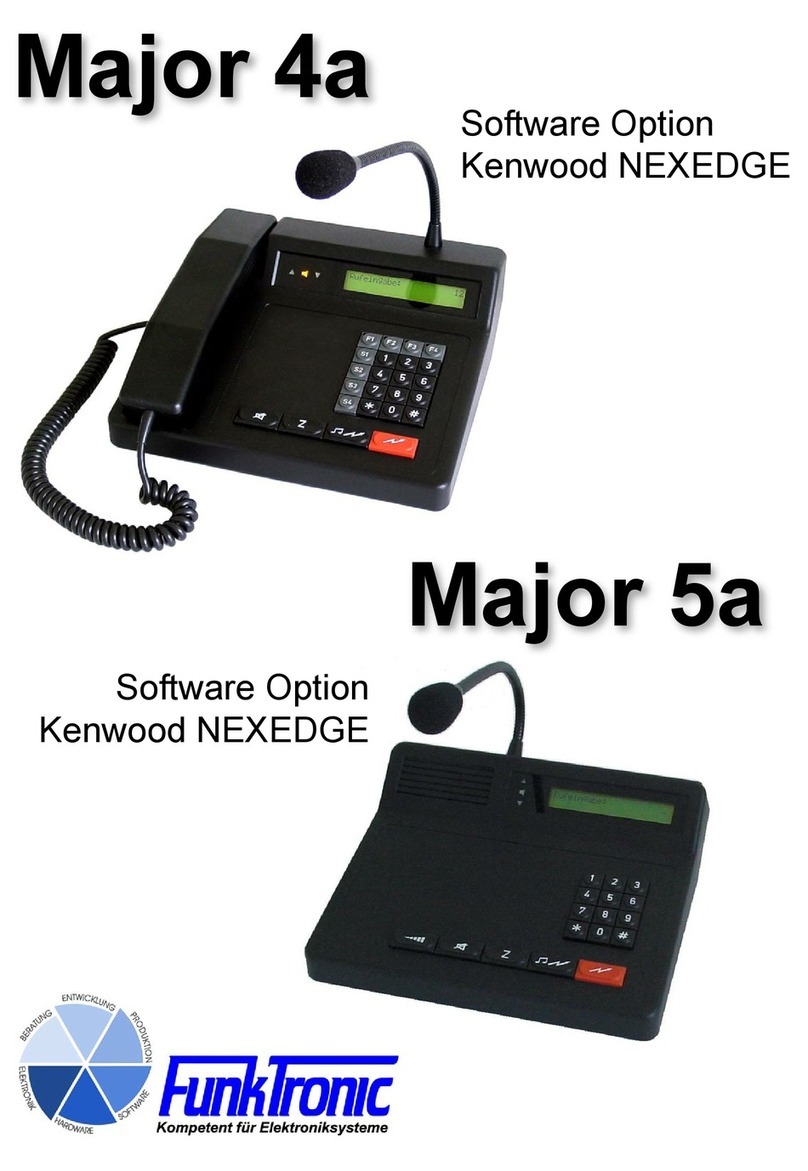
FunkTronic Major 4a User manual

Major 4a
Major 5a
English 1.0

m4a_5a (06.08.2012)
- 2 -
Kompetent für Elektroniksysteme
m4a_5a (06.08.2012) - 3 -
Kompetent für Elektroniksysteme
Page
Inhalt
Order Information 2
General Features 3
Control Elements Major 4a 4
Control Elements Major 5a 4
Display Elements Major 4a/5a 5
Sockets Pinout Major 4a/5a 6
Rearview Major 4a/5a 6
RS232 Interface 7
RS232 Cable for Flashing/Printing/Monitoring 7
Adjustments RS232 Interface 7
Keypad Layout in Programming Mode Major 4a 8
Keypad Layout in Programming Mode Major 5a 8
Differences between Major 4a and Major 5a 8
Menu Structure 9
Software Configuration 12
Programming Short Call 12
Individual Programming of the Buttons 13
Loudspeaker Button Coding 14
Encoder Prefix 15
Transmitting 6/7/8-Tone Sequences 15
Reset to Factory Defaults 16
Channel Scanning Function 16
FMS Option 16
Muting 5-Tone Sequence 16
Sample Configurations 4a/5a 17
Sample Configurations 4a/5a, DC controlled 17
Sample Configurations Major 4a/5a, AC controlled 18
Two-Wire Connection using FT630 19
Hardware Configuration 19
Two/Four-Wire Configuration 19
Connecting Major 4a/5a --> Two-Way-Radio via Multiwire 20
Connecting Major 4a/5a --> LIM-AC 20
Table of Registers Major 4a/5a 21
Keyboard Functions 27
Reset to Factory Defaults 31
Technical Data 32
Table of Tones 32
General Safety Information 33
Returning of Old Equipment 33
Release Notes 34
Order Information
Ord.-No. Description
681000 Major 4a Attention: Power supply units for Major
Major 4a with FMS option 4a/5a are not included!
Major 4a with BOS option
714000 Major 5a
Major 5a with FMS option
Major 5a with BOS option
900012 Power supply unit (230/12 Volt), suitable for Major 4a and Major 5a

m4a_5a (06.08.2012)
- 2 -
Kompetent für Elektroniksysteme
m4a_5a (06.08.2012) - 3 -
Kompetent für Elektroniksysteme
The Major 4a/5a is the newer design of the well-known Major 4/5 An alphanumeric LC Display with
background lighting has replaced the LED Display. A gooseneck microphone with a high dynamic
range is part of the standard equipment of Major 5a as well as Major 4a. By using a plain text based
menu structure the programmable features have been extended significantly and at the same time
programming has become more straightforward. All buttons are freely programmable. Hence, each
of the buttons can be assigned two different functions.
A radio set can be connected directly (multiwire) or via 2- or 4-wire line. All viable tone sequences
can be transmitted and interpreted.
There are two sockets for headsets. One can be used for a remote PTT foot switch. The 7 digital
outputs can be used for remote channel select or for other functions. For operation an external 12-
volt power supply is necessary.
The Major 4a/5a can be programmed via the serial interface or keypad. It is also possible to connect
a printer or a terminal to the serial interface. For printers with a parallel interface an additional
interface is available.
General Features

m4a_5a (06.08.2012)
- 4 -
Kompetent für Elektroniksysteme
m4a_5a (06.08.2012) - 5 -
Kompetent für Elektroniksysteme
Control Elements Major 4a
handpiece with
PTT button
gooseneck microphone
loudspeaker (LS)
button
call button
short call button PTT button
LC display
function buttons
special buttons
status LEDs
Control Elements Major 5a
loudspeaker
gooseneck microphone
loudspeaker button
call button
short call button
PTT button
LC display
status LEDs
volume button

m4a_5a (06.08.2012)
- 4 -
Kompetent für Elektroniksysteme
m4a_5a (06.08.2012) - 5 -
Kompetent für Elektroniksysteme
Display Elements Major 4a/5a
LC Display
All alphanumeric readouts are presented by a LC display with background lighting.
Status LEDs
Carrier Display (Squelch)
The carrier display LED can be controlled by voice (2-wire connection) or via squelch input
(using the radio set). If the light is on, the radio circuit is occupied, that is, a carrier signal (carrier
is keyed) is present.
PTT Display (Push-to-Talk)
The PTT display LED is on, if the transmitter is keyed. Keying of the transmitter is achieved by
pressing the PTT button during telephony or by sending a call.
Loudspeaker Display (Incoming Call)
The loudspeaker display LED is on, if the loudspeaker or the earphone capsule in the handpiece
are switched on.

m4a_5a (06.08.2012)
- 6 -
Kompetent für Elektroniksysteme
m4a_5a (06.08.2012) - 7 -
Kompetent für Elektroniksysteme
PWR operating voltage 12V, max. 1,5 A
inside: positive terminal, outside: earth
Rearview Major 4a/5a
Pinout I/O
Digital In/Outputs (ST3)
IN/OUT 0 1
IN/OUT 1 2
IN/OUT 2 3
IN/OUT 3 4
IN/OUT 4 5
IN/OUT 5 6
IN/OUT 6 7
GND 8
Pinout RS232
(ST4)
NC 1
NC 2
TxD 3
RxD 4
GND 5
NC 6
Pinout S/E
Radio Circuit (ST1)
AF input B 1
AF input A 2
Squelch input 3
GND 4
output +12 V, max. 200 mA 5
sender keying active, low 6
AF output A 7
AF output B 8
Pinout PTT
Headset (ST2)
GND 1
GND AF input (mic. -) 2
NF earphone 3
GND earphone 4
AF input (mic. +) 5
PTT, active GND 6
Sockets Pinout Major 4a/5a
All AF in/outputs are equipped with transformers
and, hence, potential-free. PIN 5 is for supply
(+12V) of external devices (LIM-AC, FT634C,
FT633AC).
Attention: Do not use PIN 5 to supply a radio
set. 200 mA output current is not sufficient.
There are two sockets for connecting a headset.
One is for connecting the headset, the other
for the use of an external PTT button (e.g. foot
switch)
The digital connections can be configured as
inputs or outputs, respectively. Usually, these are
used as outputs for remote channel select. To socket RS232 a printer can be connected.
All of the schemes show the sockets as viewed from the rear of the Major.
ST1
ST2AST4 ST2ST3PWR
Pinout HS
Headset (ST2A)
GND 1
AF input (mic. +) 2
AF earphone 3
GND earphone 4
GND AF input (mic. -) 5
PTT, active GND 6

m4a_5a (06.08.2012)
- 6 -
Kompetent für Elektroniksysteme
m4a_5a (06.08.2012) - 7 -
Kompetent für Elektroniksysteme
5 GND
ST4 RS232 Interface
RS232 Interface
Pinout
RS232 ST4
1
2
3
4
5
6
RS232 Cable for Flashing/Printing/Monitoring
7 GND
2 TxD RS232
3 RxD RS232
RS232 25-pin connector on computer RS232 socket on Major
TxD
RxD
GND
Pinout
RS232 ST4
1
2
3
4
5
6
TxD
RxD
GND
3 TxD RS232
2 RxD RS232
RS232 9-pin connector on computer RS232 socket on Major
Adjustments RS232 Interface
9600 baud, 8 data bits, no parity, 1 stop bit, no protocol

m4a_5a (06.08.2012)
- 8 -
Kompetent für Elektroniksysteme
m4a_5a (06.08.2012) - 9 -
Kompetent für Elektroniksysteme
Keypad Layout in Programming Mode Major 4a
Button reduces by 1 and button increases
by 1.
To the buttons S1 bis S4, * and # the values A
to F are assigned.
¡13
5
4
8
2
0
9
*
7
6
#
A
EF
+
-
S1
¡
B
S2
¡
C
S3
¡
D
S4
1 3
54
8
2
0
9
*
7
6
#
A B C
D E F
Keypad Layout in Programming Mode Major 5a
Long pressing of the buttons 1 to 6 allows to
achieve the additional values A to F.
The call button reduces by 1 and the PTT but-
ton increases by 1.
+
-
Major 4a and Major 5a show the following differences:
1. different keyboards
2. Major 4a includes a handset, Major 5a does not
3. minor differences in the software, resulting from 1. and 2.
4. optional telephone interface only for Major 4a
Differences between Major 4a and Major 5a

m4a_5a (06.08.2012)
- 8 -
Kompetent für Elektroniksysteme
m4a_5a (06.08.2012) - 9 -
Kompetent für Elektroniksysteme
Menu Structure
Simultaneuos pressing of the buttons * and # opens the menu.
Due to the different keypad designs, for the same operations different keys are used in Major 4a and
Major 5a. In the following, the handling of Major 4a is described. For the respective keys that have
to be used in Major 5a please consider the table below.
Function Major 4a Major 5a
next menu *
select menu item #
escape discarding changes *
save changes and escape #
increase value by 1
reduce value by 1
- enter the register number
to be programmed
- with 222 the factory default
values are programmed
- overwrite the code with the
desired values
1 = input level
nominal value: 300mV
indicated on the display
2 = output level
as required
3 = GN microphone level *
* and #
È
ÆÆ
È È È
- displayed 3 seconds
- the potis can be adjusted
from 0 to 255
- input directly via keypad
or
= increase value by 1
= reduce value by 1
= escape menu
discarding changes
= save changes,
escape menu
= escape menu
discarding changes
= save changes,
escape menu
select number:
EEPROM programming : F4
Next menu : F3
Software Version : F4
Next menu : F3
Level settings : F4
Next menu : F3
Register: Software: Major 4a V1.24
Date : 23.09.04
Poti-Nr. (1-6):
Register: 000
Code 12345
*
GN = gooseneck
HA = Handapparat
HS = Headset

m4a_5a (06.08.2012)
- 10 -
Kompetent für Elektroniksysteme
m4a_5a (06.08.2012) - 11 -
Kompetent für Elektroniksysteme
0 = 200 Hz
1 = 300 Hz
2 = 400 Hz
3 = 600 Hz
4 = 800 Hz
5 = 1000 Hz
6 = 1600 Hz
7 = 2400 Hz
8 = 3400 Hz
9 = 4000 Hz
S1 = 2900 Hz
S2 = 3000 Hz
S3 = 3100 Hz
S4 = 3300 Hz
* = 1200 Hz
# = 1800 Hz
= escape menu
* und #
È
continued
ÆÆÆ
È
Æ
È
= reduce contrast by 1
= increase contrast by 1
= escape menu
discarding changes
= save changes,
escape menu
È
Æ
= one digit to the left
= one digit to the right
= escape menu
discarding changes
= save changes,
escape menu
The values can be changed
directly using the buttons 0
to 9.
Menu Structure
select number:
Transmit test tone : F4
Next menu : F3
Change frequency 0.....C
F3 for ESC Hz
Kontrast einstellen : F4
nächstes Menü : F3
Displaycontrast: 90
F1- F2+ F3ESC F4STORE
Datum/Uhr einstellen: F4
nächstes Menü : F3
15.10.04 22:47:01

m4a_5a (06.08.2012)
- 10 -
Kompetent für Elektroniksysteme
m4a_5a (06.08.2012) - 11 -
Kompetent für Elektroniksysteme
The onboard clock is factory
calibrated. Before changing
the values please note down
the current values. Higher
values accelerate the clock,
while lower values slows
it down. Changes made
in digital have more effect
than changes made in ana-
log. Fine adjustment must
be done in analog, step by
step.
* und #
È
continued
ÆÆÆ
È
Æ
- displayed for 3 seconds
ÆÆÆ
= escape menu
discarding changes
= save changes,
escape menu
= one digit to the left
= one digit to the right
Menu Structure
select number:
Adjust clock : F4
Next menu : F3
Digital (0-6) : 3
Analog (00-59): 29
Serial number : F4
Next menu : F3
Serial number: 0123/06
Mainboard: 0456/06

m4a_5a (06.08.2012)
- 12 -
Kompetent für Elektroniksysteme
m4a_5a (06.08.2012) - 13 -
Kompetent für Elektroniksysteme
The impacts of the single digits of register 174 are
as follows:
1. digit = 2 --> function --> transmit call
2. digit = 2 --> transmit short call
3. digit = F --> input necessary
4. digit = 0 --> ID mode / 5 tone sequence
5. digit = 1 --> not applicable for 5 tone
sequence
Programming of register 174 is achieved following
the procedure below. Register 175 is programmed
analogously.
Software Configuration
Programming Short Call
The example below shows the programming of
short dial 1 in register 001 with tone sequence
12345.
Please press the following buttons:
* and #
0
È
0
1
È
È
The line „Code“ shows the current programming.
You can overwrite these with your own values.
The menu can be quit without changes at all times
using button
Button stores the displayed values.
As every button of the Major 4a/5a is freely
programmable, registers 174 and 175 have to
be programmed with the appropriate values of
the short call button (Z-button).
Commonly, reigister 174 (function of Z-button,
short) is programmed with 22F01 and register
175 (function of Z-button, long) is programmed
with 00000. The first zero in register 175 disables
action after long pressing of the Z-button
* and #
1
È
7 4
È
È
È
È
È
select number:
EEPROM programming : F4
Next menu : F3
Register:
Register: 001
Code 12345
select number:
EEPROM programming : F4
Next menu : F3
Register:
Register: 174
Code 22F01
Register: 174
EEPROM programmed
Register:
Funk Tronic Major 4a
select number:

m4a_5a (06.08.2012)
- 12 -
Kompetent für Elektroniksysteme
m4a_5a (06.08.2012) - 13 -
Kompetent für Elektroniksysteme
Individual Programming of the Buttons
It is possible to program each button of the
Major 4a with two different functions.
The duration of pressing the button (short or
long pressing) decides, which of the functions
is exercised. If a button is pressed shorter
than a second, the function programmed as
“button, short“ is exercised. Pressing it longer
than a second triggers the function “button,
long“. If no function is programmed for “button,
long“, the function “button, short“ is exerciesed
immediately.
Each register consists of 5 digits. The value of the
first digit is important to define the function (see
also: Keyboard Functions). The choices available
for digits 2-5 depend on the function chosen by
the first digit.
Below you can find an example for the
programming of button 1.
Programming
“
button, short“:
(short tapping)
1. digit 7 = function --> enter selected number
2. digit 1 = enter number --> new input
3. digit 1 = input value 0 bis F, here: 1
4. digit 0 = not applicable
5. digit 0 = not applicable
Usually, the function for long pressing of button
1 is not programmed. However, as an example
the speaker volume is set to level 1.
Programming “button, long“:
(long pressing)
* and #
1
È
3 3
È
È
* and #
1
È
3 2
È
È
select number:
EEPROM programming : F4
Next menu : F3
Register:
Register: 132
Code 71100
È
È
È
The following steps are necessary to save the
changes made in the register.
Register: 132
EEPROM programmed
Register:
Funk Tronic Major 4a
select number:
select number:
EEPROM programming : F4
Next menu : F3
Register:
Register: 133
Code 00000

m4a_5a (06.08.2012)
- 14 -
Kompetent für Elektroniksysteme
m4a_5a (06.08.2012) - 15 -
Kompetent für Elektroniksysteme
Loudspeaker Button Coding
This example shows the coding of the loudspeaker
(LS) button for adjusting the loudness when
pressed for a longer time.
* und #
1
È
7 7
È
È
select number:
EEPROM programming : F4
Next menu : F3
Register:
Register: 177
Code 41F09
The parameters for pushing the LS button are
coded in register 177.
1. digit 4 = function --> volume
2. digit 1 = adjust volume
3. digit F = manual input
4. digit 0 = minimum volume
5. digit 9 = maximum volume
È
È
È
The following steps are necessary to save the
changes made in the register.
Register: 177
EEPROM programmed
Register:
Funk Tronic Major 4a
select number:
Register: 133
Code 41109
The value 00000 in register 133 must be set to
41109 and saved subsequently.
1 1 0
È
94
1. digit 4 = function --> volume
2. digit 1 = adjust volume
3. digit 1 = volume level: 0 bis F, here: 1
4. digit 0 = minimum volume
5. digit 9 = maximum volume
Again, the following steps are necessary to store
the applied changes.
È
È
È
Now tap button 1 once short and once long (in
menu “select number:“). After short pressing the
display shows 1, long pressing activates volume
level 1 of the loudspeaker.
Register: 133
EEPROM programmed
Register:
Funk Tronic Major 4a
select number:

m4a_5a (06.08.2012)
- 14 -
Kompetent für Elektroniksysteme
m4a_5a (06.08.2012) - 15 -
Kompetent für Elektroniksysteme
Transmitting 6/7/8-Tone Sequences
Encoder Prefix
Register 010 defi nes the number of permanently
programmed prefix digits and, hence, also the
number of the arbitrary digits.
If „FFFFF“ is programmed in register 010, all
5 digits have to be entered via the keypad.
For example, if digit 1, 2 and 4 are permanent
(values 3, 4 and 5) and digit 3 and 5 have to be
entered via the keypad, register 010 must be
programmed with 34F5F.
EEEEE switches off the input prompt (“select
number:“).
* und #
0
È
1 0
È
È
È
È
È
select number:
EEPROM programming : F4
Next menu : F3
Register:
Register: 010
Code FFFFF
Register: 010
EEPROM programmed
Register:
Funk Tronic Major 4a
select number:
To transmit an 8-tone sequence upon pressing
the call button, the following register entries are
necessary. Here, the first 5 digits are entered via
the keypad (or depend on the entry in register
010 --> Encoder Prefix) and the last 3 digits are
attached from register 015.
* und #
0
È
1 5
È
È
1 7 2
È
Register 172:
2 = function --> transmit call
0 = entered call
0 = not applicable
5 = 8 tone sequence
0 = not applicable
The 8-tone sequence consists of the 5 digits that
are entered via the keypad followed by the last
3 digits from register 015 (personal identification
code).
select number:
EEPROM programming : F4
Next menu : F3
Register:
Register: 015
Code 98765
Register:
Register: 172
Code 20050

m4a_5a (06.08.2012)
- 16 -
Kompetent für Elektroniksysteme
m4a_5a (06.08.2012) - 17 -
Kompetent für Elektroniksysteme
Reset to Factory Defaults
Channel Scanning Function
The channel scanning function is activated if the
waiting time in register 067/5 is programmed NOT
to be zero. Zero deactivates this function.
The scanner will wait for at least the programmed
waiting time per channel. Just before the end of
the waiting time, the channel is checked for a
carrier. If no carrier is detected the next channel
will be scanned.
Scanning will stop when a carrier is detected
if “scanner stops on carrier“ (register 068/1) is
programmed. If not the scanner will be stopped
for an additional 100 ms. During this time the
scanner will scan for a tone. If a tone is detected,
the scanner will wait for the scan waiting time
(068/2+3). If a call is decoded during that time
the scanner stops. Otherwise the next channel
is scanned.
The channel range programmed in register
067/1-4 will be scanned. If register 067/1+2 is
programmed with ‘EE’ the specified channels
programmed in register 070-074 (EEPROM
table) will be scanned. Scanning the table can
be aborted by pressing FF.
In order to scan channels 1, 5 and 6, register 070
is programmed with 0105x and register 071 with
06FFx.
After decoding a call the scanner stops for the
programmed loudspkeaker time (050/1-3) which is
retriggered by a carrier and/or PTT. Furthermore,
the scanner can be switched off by activating the
loudspeaker (LS button) manually.
Scanning can be initiated by hanging up the
handpiece (050/5). The scanner can also be
activated using the “loudspeaker off” function
(function 4; second digit: 0).
Using the following steps, Major 4a can be reset
to factory defaults.
Attention! All parameters are reset to the
default values without further confirmation.
* and #
2
È
2 2
È
È
select number:
EEPROM programming : F4
Next menu : F3
Register:
program EEPROM with
default values
select number:
By entering 223 instead, the potis are also
reset.
FMS Option
The FMS option allows for the status input and
the reception of orders according to the German
Funkmeldesystem (FMS).
As for this option buttons 0-9 are used as status
buttons, manual selection of a 5-tone sequence
is not possible.
Muting 5-Tone Sequence
Muting (Register 018) is triggered by the first
two tones and lasts until the end of the tone
sequence. The first tone must be a valid tone in
terms of duration. As soon as the second tone
is recognized, handpiece and loudspeaker are
muted. For digits that are programmed with ‘F‘,
all tones are valid. To disable muting ‚EE‘ is
programmed.

m4a_5a (06.08.2012)
- 16 -
Kompetent für Elektroniksysteme
m4a_5a (06.08.2012) - 17 -
Kompetent für Elektroniksysteme
7 AF, Squelch, PTT
max. 8 channel remote control
(7 Bit + GND)
Sample Configurations 4a/5a, DC controlled
The following situation shows the easiest way for remote radio control using a Major 4a/5a. If a remote
control is not required, a 7-wire line is sufficient for AF, squelch and PTT.
If only a local 2-wire line is available the following set-up using a DC line interface FT630-2 is highly
recommended. In this configuration remote channel select and duplex mode are not possible.
2
FT630-2
without remote
channel control
2
Several control panels in parallel circuit
2
2
FT624
2
2
FT630-2
without remote
channel control
Sample Configurations 4a/5a

m4a_5a (06.08.2012)
- 18 -
Kompetent für Elektroniksysteme
m4a_5a (06.08.2012) - 19 -
Kompetent für Elektroniksysteme
2
LIM AC
LIM AC
2 oder 4
FT634C or
FT633AC or
LIM-AC (only 2-wire) FT634C (with remote channel control) or
FT633AC (with remote channel control) or
FT634 (without remote channel control)
Several control panels in parallel circuit --> LIM AC has to be equipped with a notchfilter to suppress
the PTT keying tone.
2
2
FT624
Sample Configurations Major 4a/5a, AC controlled
2
2
2
2
2
2
FT630-2
without remote channel control
FT630-2, only if carrier
signaling is to be transmitted!
2 x FT630-2, only if carrier
signaling is to be transmitted!
Example for duplex mode mit 4-wire transmission.
FT634C (with remote channel control) or
FT633AC (with remote channel control) or
FT634 (without remote channel control)

m4a_5a (06.08.2012)
- 18 -
Kompetent für Elektroniksysteme
m4a_5a (06.08.2012) - 19 -
Kompetent für Elektroniksysteme
Hardware Configuration
The Major 4a/5a can be configured for 2-wire and 4-wire connection. Starting with software version
2.0 switching from 2-wire to 4-wire is done by programming register 051/4.
Two/Four-Wire Configuration
Two-Wire Connection using FT630
Over longer distances the radio set can be controlled via a 2-wire line. If PTT is keyed at the Major, a
DC voltage is applied to the line in addition to the audio signal. This voltage is analyzed in the FT630-
2 and the PTT relay turns on the transmitter. In the reverse situation the FT630-2 is able to apply a
DC voltage to the line if an incoming signal (squelch) is present.
If the DC voltage is used for transmitter keying as well as for detection of an incoming signal, no
transmission is possible while a squelch signal is detected.
Instead of the FT630-2 (DC) the line interfaces FT634C, FT634 oder FT633AC can also be used. For
these no DC coupling is necessary and additional features are available, e.g. the transmission via
digital in-/outputs (alarm in case of dysfunction, housebreaking, fire...) and remote channel control.
Register 069/1 defines if PTT keying is conducted by the PTT keying tone or by a DC voltage.

m4a_5a (06.08.2012)
- 20 -
Kompetent für Elektroniksysteme
m4a_5a (06.08.2012) - 21 -
Kompetent für Elektroniksysteme
Connecting Major 4a/5a --> Two-Way-Radio via Multiwire
All audio in/outputs of the Major 4a/5a are equipped with transformers and hence are potential-free.
If no potential-free in/outputs are available at the radio, in both cases one of the audio connections
has to be grounded, preferably by connecting pins 1 and 8 to GND pin 4. Switching from 2- to 4-wire
is carried out by programming register 051/4.
PIN 5 is for supply (+12V) of external devices (LIM-AC, FT634C, FT633AC).
Attention: Do not use PIN 5 to supply a radio set. 200 mA output current is not sufficient.
Connecting Major 4a/5a --> LIM-AC
The LIM-AC can be connected to Major 4a/5a with a 8-terminal line. Commercially available computer
cables may be used.
Other manuals for Major 4a
4
This manual suits for next models
1
Table of contents
Other FunkTronic Microphone System manuals