Hollyland-Tech Cosmo 1000 User manual

HOLLYLAND Cosmo 1000
User manual
Copyright © 2015 Hollyland. All rights reserved.
Long Range Wireless HDMI/SDI HD Video Transmission Suite


About
Product model and standard:
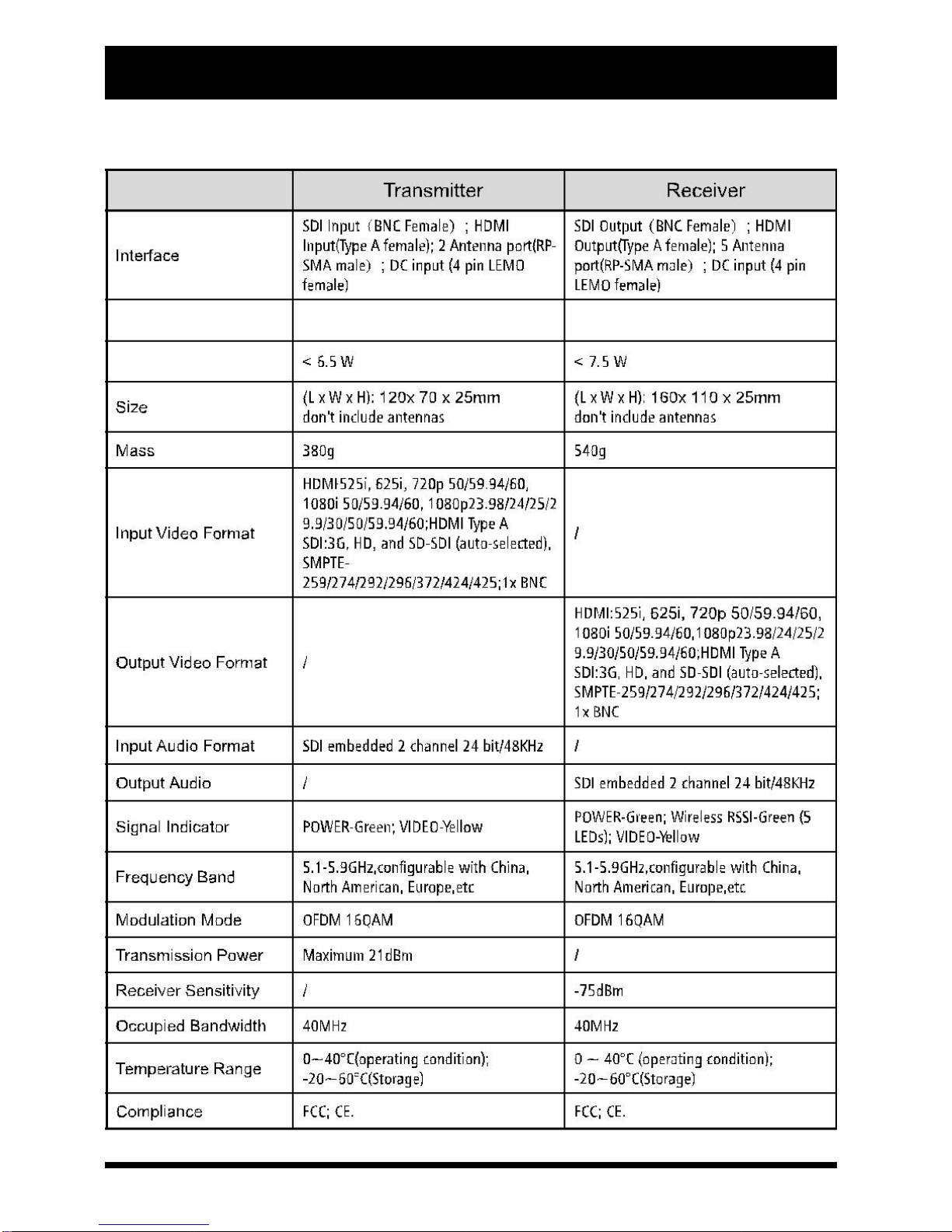
Hollyland Cosmo 1000 Long Range Wireless HDMI/SDI Transmission Suites
utilize today's most advanced wireless video transmission technology, which
can realize the broadcast-class and uncompressed 3G SDI/HDMI HD video
signal transmitted with no compression and zero delay. The suite includes
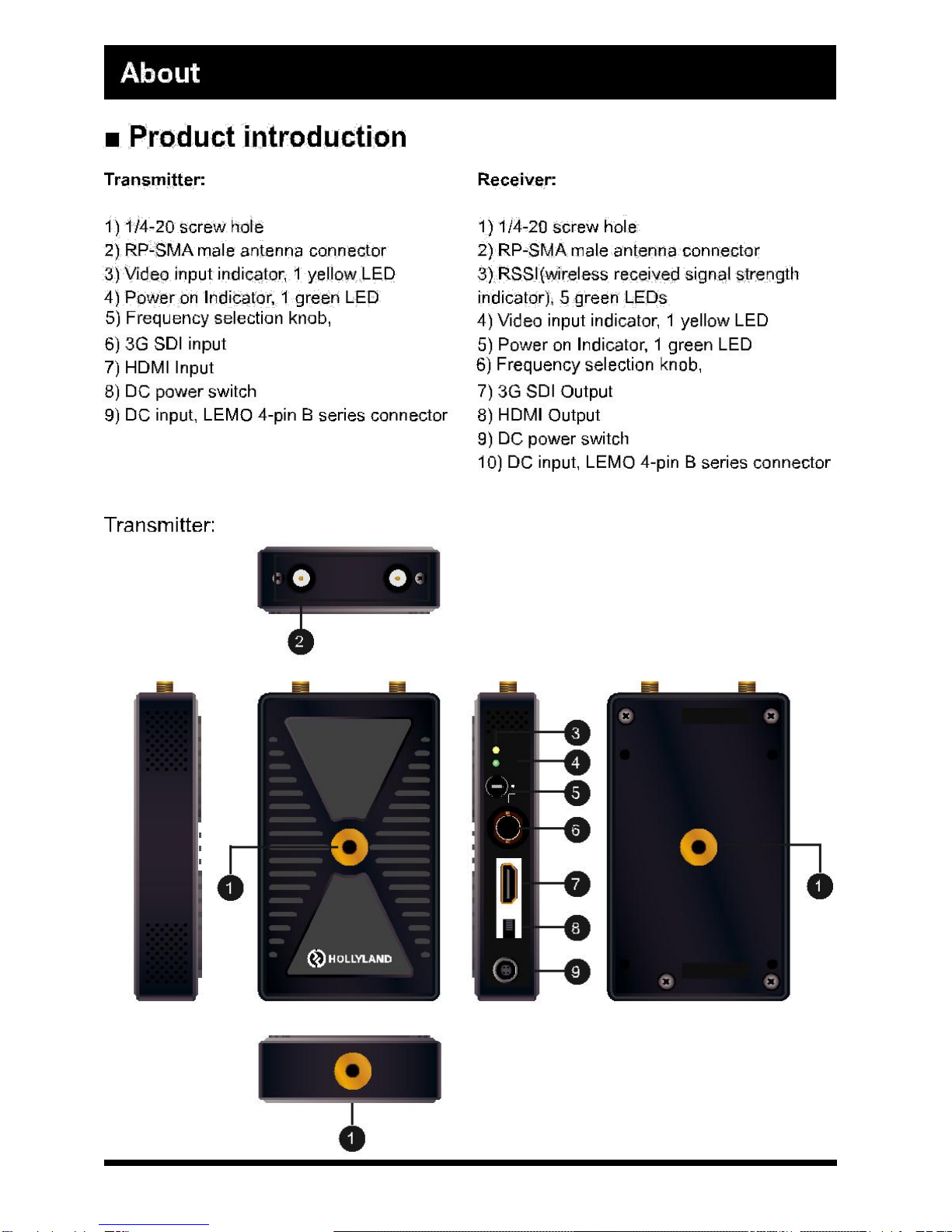
one transmitter and one receiver, where the transmitter provides a 3G/HD
SDI input and a HDMI input, and the receiver also provides a 3G/HD SDI
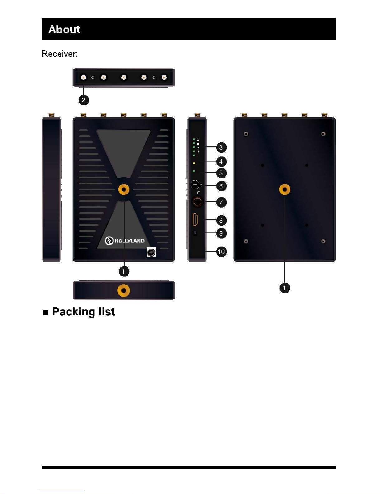
output and a HDMI output. The wireless HD suite have 2 stick antennas in
transmitter side, and 5 stick antennas in receiver side, and it can work in 5.1-
5.9GHz frequency band and be flexibly software configured to licensed or
ISM band of glob-al different regions, as well as the side panel of both
transmitter and receiver have been installed a frequency select knob, which
provides maximum 10 workable frequency channels, and supports maximum
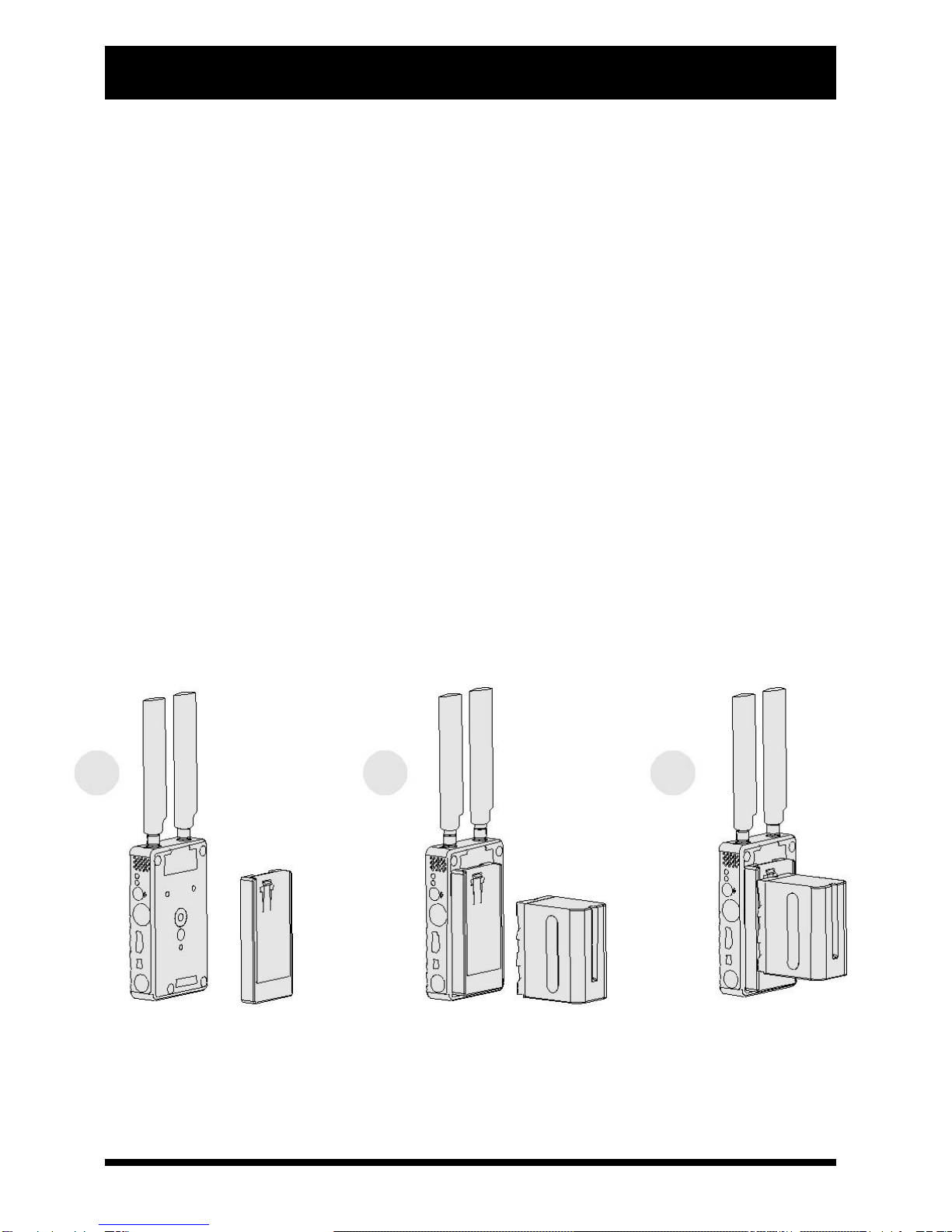
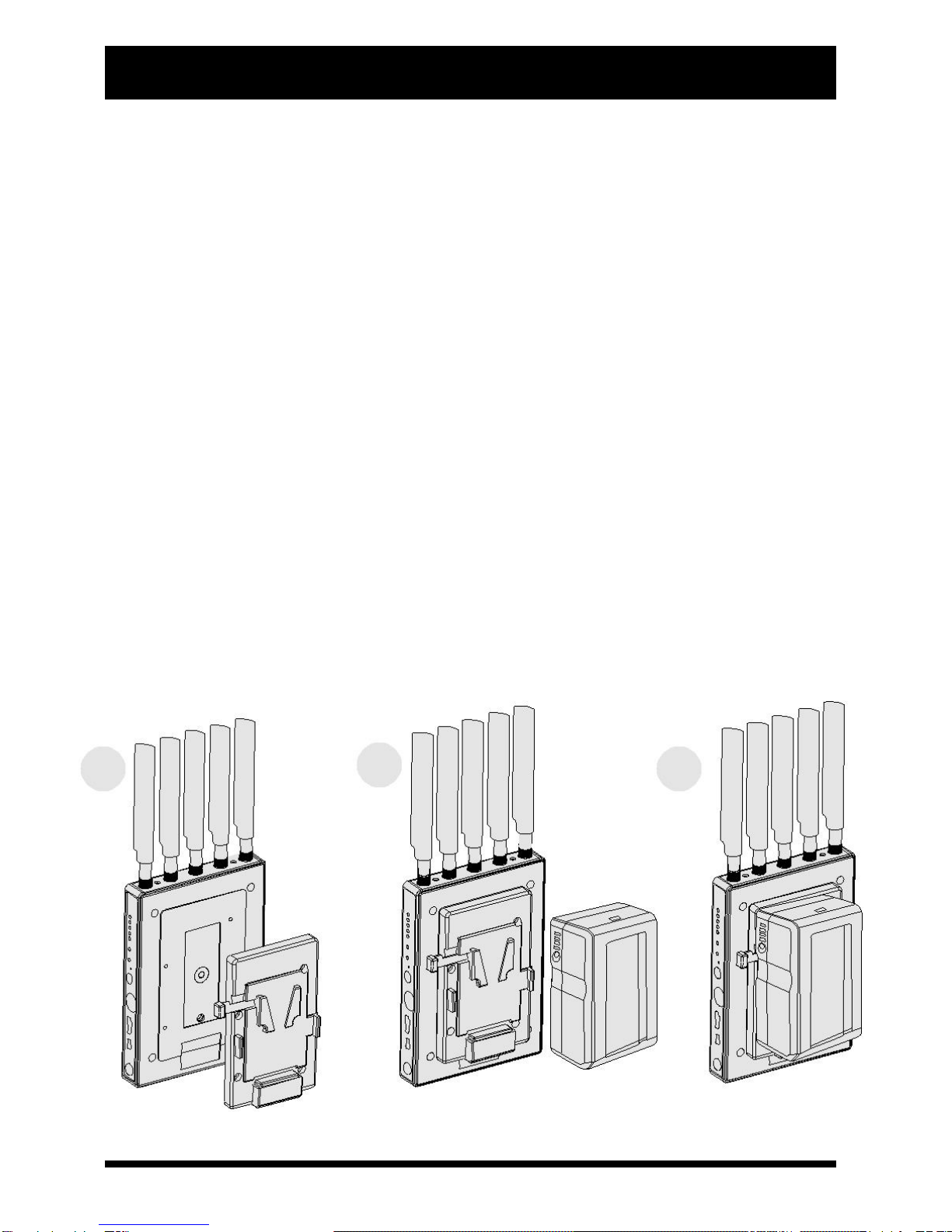
4 sets working simultaneously. The wireless suite can accept wide range DC
power input, which is suitable for many kinds of camera battery model. The
suite also can sustain ±8 kV ESD (HBM, contact discharge), the industry
class metal case and professional heat design would guarantee most
rigorous reliability.
3

About
Main features:
●HDMI 1.3 spec supports
●HDMI and 3G SDI inputs and outputs
●Highest resolution 1080p 60Hz, no delay and no compression
●AES-128 encryption with air interface HD video data stream
●Support point to point, and point to multi points network topology
●Each RX can be paired to the unique TX in factory
●5GHz ISM frequency band, maximum 10 frequency channels selected
by user knob, coexist with WIFI
●Maximum transmission distance is 300 meters
●Signal indicators for DC power status, video status and receiver RSSI
●Wide range power voltage input, adapt most kinds of camera batteries
●Optional Sony F970, V-mount and G-mount, battery buckle, convenient
for field battery install and replacement
●Any input and output ports with ±8 kV ESD protection level (HBM,
contact discharge)
●Industrial metal case, stable and reliable
4

About
Parameters
:
Supply Voltage Range
7-36V DC
7-36V DC
Power Consumption
5

0-9
0-9
2
3
Power Video
4
1
2
34
001
5
9
6
887
SDIin
On/Off
HDMIin
DCin
6

Max
Min
Video
Power
223
34
1
1
4
0
0
55
9
6
9
8
787
Out
SDI
Out
HDMI
On/Off
DCin
1 unit transmitter
1 unit receiver
8 pcs 5GHZ omni-directional and high efficiency
antennas (SMA female)
2×flat screwdrivers
1×7'' articulating arm
1×1/4-20 screw to ISO518 hot shoe converter
1× crab clam
2× D-Tap to 4-pin lemo converter cable
1 user manual
355X272X105.38MM tool case packing
7

Installation
Installation details and cautions
●Transmitter side
a) Install 2 omni-directional and high efficiency antennas to transmitter’s
RP-SMA male antenna connectors.
b) There are 3 1/4-20 screw nuts in transmitter metal case, which are
located on surface, rear and bottom. So the user can utilize a 1/4 screw to
ISO518 hot-shoe converter fix the transmitter on camera.
c) Install battery into battery buckle if your product model includes battery
buckle option; please note the battery model must match the battery buckle
type.
d) The user can also utilize a subsidiary LEMO 4 pin male to D-type recep-
tacle power cable to get power input from an outside power source.
e) All TX installation guidelines see below figure.
123
8

Installation
●Receiver side
a) Install 5 pcs omni-directional and high efficiency antennas to receiver’s
RP-SMA male antenna connectors.
b) There are a 1/4-20 screw nut in the surface side of receiver. The
user can utilize a 1/4 screw fix the subsidiary metal hook with the receiver.
c) Install battery into battery buckle if your product model includes the op-
tion of battery buckles; please note the battery model must match the battery
buckle type.
d) The user can also utilize a subsidiary LEMO 4 pin-male to D-type recep-
tacle power cable to get power input from an outside power source.
e) All RX installation guidelines see below figure.
123
9

Installation
Typical connection instruction
Connect camera SDI or HDMI output to transmitter SDI or HDMI input port,
and the transmitter can fixed in hot-shoe port of the camera. Connect HDMI
or SDI output port of the receiver to SDI or HDMI input port of the HD moni-
tor. Make sure all antennas and batteries are equipped normally. See below
figure.
10

Operation instruction
Getting started
After finishing all steps above, system is workable, follow below steps.
a) Ensure the video source output of the camera is OK, and the HD
monitor is power on and switched to connected video input port.
b) Ensure all inputs, output SDI or HDMI cables are connected.
c) Ensure all antennas are installed, and it is better to keep TX 2 anten-
nas and RX 5 antennas with orthogonal angle each other for best RF
perfor-mance. Looks like below figure.
Transmitter Receiver
d) Ensure both the transmitter and receiver installed batteries or DC input
ports connected to outside power soutces. Then toggle power switch of trans-
mitter and receiver to ‘ON’ respectively then ‘Power’ indicator will light.
e) Ensure the frequency knobs of transmitter and receiver are set with
the same number and this will make sure the transmitter and receiver work
with same RF
f) If the camera is on and video input is OK, TX side ‘video’ indicator
will light.
11

Operation instruction
g) Before RX setup wireless link with TX, 5 ‘RSSI’ indicators and “video”
indicators will be off; when wireless link is OK, ‘RSSI’indicators will light first,
and ‘RSSI’will indicate the received RF signal strength. If the receiver detects
normal wireless video internally from air interface, ‘Video’indicator will light.
Before that if SDI or HDMI video out port of the receiver has HD monitor
connected it will display an OSD of ‘Link connecting……’looks like below
picture.
h) The system will spend 20-30 seconds on constructing communication link,
and the real link period will depend on the current wireless channel condi-tion.
When wireless link is set up, ‘RSSI’ light will light and indicate current received
wireless signal strength, as well ‘video’ indicators will light, and then connected
HD monitor will display the video and audio accordingly.
i) For the best wireless transmission performance, it need install the trans-
mitter and receiver more than 2m above the ground and keep the same
height, and make sure no obstacles between them; Moreover, it is the best
to keep the transmitter antennas and the receiver antennas face to face, and
don’t turn round any sides with too big angle. The real transmission distance is
also relevant to current air electromagnetic environment, because the system
works in ISM band,it is exposure to all kinds of 5GHz band air interference, we
suggest the users should do a manual frequency sweep by adjusting frequen-cy
selection knob with a circle before using the equipment, then choose the best
frequency channel for stable performance.
12

Operation instruction
Input video ports selection of transmitter
The transmitter has a 3G SDI video input port and a HDMI video input port,
and the system will detect valid video source automatically of SDI and HDMI
port, then switch it as main video input channel. If both SDI and HDMI have
valid video inputs, the system will take SDI input as priority.
RSSI indicators
The receiver will calculate received RF signal strength internally and 5 “RSSI”
LEDs will be used to indicate wireless signal power and quality. The user can
observe the RSSI LED status to know if the current wireless link is reliable or not.
Lit RSSI LEDs Volume
Wireless Link Quality
Video Quality
4-5
Strong
Best
2-3
Middle
Good
1 or no lit LED
Weak
Visible Video Noise
Frequency selection and configuration
The wireless suite can work in 5.1-5.9GHz frequency band and be flexibly
software configured to licensed or ISM band of global different regions as
well as the side panel of both transmitter and receiver has been installed a
frequency select knob, which provide maximum 10 workable frequency
channels, and support maximum 4 sets working simultaneously. See
below frequency knob figure.
1
2
3 4
0
9
8
7
5
6
13

Maintenance
Storage conditions
Products storage temperature should be -20 C~60 C. For long time storage
requirement, please use original carbon boxes, and avoid from high humid,
acid base or dusty place.
Maintenance
Warning
To ensure your safety, please choose well-known brand DC batteries, and
guarantee suitable work conditions that batteries manual mentioned.
14

Trouble shooting
Normal problems
a) No output on display
Check TX and RX power first, and see if TX or RX battery is powered from ex-
ternal power, then check if TXantennas andRXantennas are installed right.
After that, check ‘video’ indicator, if TX ‘video’ indicator is not light, then checkSDI
or HDMI cable and video source please. Finally may check input v-i
deo format is compatible with this product specs.
b) Poor output video quality
Check if SDI or HDMI input or output cable is plugged well, then checks how
many receiver side ‘RSSI’ LEDs are lit, there should be 2-3 RSSILEDs lit if
the user want to get better video quality; if there is only 1 RSSI LED lit, that
means the received wireless signal is weak and should shorten the transmis -
sion distance.
15

For more information on Hollyland series systems,
please check :www.hollyland-tech.com
Distributed by
Phone: 0415 468 731, Email: sales@ultralinks.com.au
Suite 1A Level 2, 802 Pacific Highway, Gordon NSW 2072
www.ultralinks.com.au
Table of contents