Phihong AW Series User manual
Electric Vehicle AC Charger
AW Series - User Manual
COPYRIGHT © 2020 Phihong Technology reserves the right to make changes to this product without further notice.
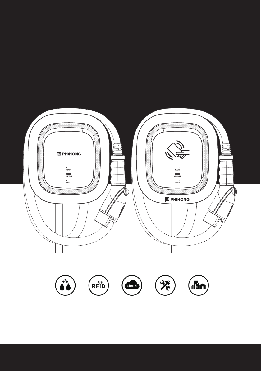
IP55 Authorization Management Repairable Outdoors
version. W84A99900121-HB4
Non-Networking EditionNon-Networking Edition Networking EditionNetworking Edition

Please visit the official website to obtain the latest
version of user manual before installation.
Website:www.phihong.com.tw

CONTENT
1. Important Safety Instructions ..........................................................1
2. Interface ............................................................................................3
2.1 Non-Networking Edition ............................................................3
2.2 Networking Edition .....................................................................4
3. Dimensions .......................................................................................5
3.1 Main Size of Charger .................................................................5
3.2 Wall-Mount Bracket ...................................................................6
4. Specification .....................................................................................7
5. Design Standard ...............................................................................8
6. Status Description of the Charger ...................................................9
7. Installation Instructions .................................................................11
7.1 Packing List ..............................................................................12
7.2 Tools and Materials Required .................................................13
7.3 Wall-Mount Bracket Installation Requirements .....................13
7.4 AW Installation Requirements .................................................13
7.5 4G Installation Steps (4G version) ..........................................14
7.6 Installation Steps .....................................................................15
8. Operating Instructions ...................................................................18
8.1 Operating Procedures ..............................................................18
8.2 Operating Steps – Non-Networking Edition ..........................18
8.3 Operating Steps – Networking Edition ...................................19
8.4 Time setting (Networking, Wi-Fi and 4G Editions) .................20
8.5 Wi-Fi Setup (for the optional Wi-Fi Edition) ...........................22
8.6 4G Setup (for the optional 4G Edition) ....................................23
8.7 Re-checking the Wi-Fi and 4G Signal Strength on Power-Up.
.........................................................................................................24
8.8 Error and Warning Message ....................................................26
9. Federal Communication Commission Interference Statement ...27
10. Industry Canada statement .........................................................28
11. Maintenance and Repair ..............................................................30
11.1 Daily Maintenance ...............................................................30
11.2 Maintenance Spares ............................................................30
11.3 Warranty and Maintenance .................................................30
11.4 Maintenance History ...........................................................32

1. Important Safety Instructions
Please read all Important Safety Instructions as well as charging instructions
in your vehicle owner’s manual before attempting to charge your electric
vehicle. Failure to do so can result in death or severe injury. Save this user
manual for future reference. There are many safety features built into the
charger. Read all the safety information and warnings in this manual to be
avoid any risks or hazards and risks associated with using this charger.
Warning
When using electric products, basic precautions should always be followed.
This manual contains important instructions, including the following, that
must be followed during installation, operation and maintenance.
• Do not install or use the charger near flammable, explosive, corrosive, or
combustible materials, chemicals, or vapors.
• Turn off the input power of the charger before performing any
maintenance to the charger.
• The device is designed only for vehicles that are compatible with the SAE
J1772 Level 2 charging standard.
• Do not use the charger if it is defective, appears cracked, frayed, broken or
damaged.
• Do not attempt to open, disassemble, repair, tamper with, or modify
the charger. Contact our Customer Service department if you have any
questions or require any parts replacements or repairs.
• Do not use the charger when you are, the vehicle is, or the charger is
exposed to severe rain, snow, or other severe weather.
• When transporting the charger, handle it with care and do not drag or step
on the device.
• Do not touch the charging connector terminal with any sharp metallic
objects to preventing damage.
• Do not forcefully pull the charging cable, damage it with sharp objects, put
ngers, or insert foreign objects into any part of the charging connector.
• Risk of explosion. This device has arcing or sparking parts that should
AW Series - User Manual
1

not be exposed to flammable vapors.
• Risk of electric shock. Do not remove cover or attempt to open the
enclosure of the device. There are no user-serviceable parts inside.
Contact a qualied service company if you require any service repairs.
• To reduce the risk of re, this charger should only be connected to circuit
overcurrent protection in accordance with the National Electrical Code,
ANSI/NFPA 70, and the Canadian Electrical Code, Part I, C22.1.
• This charger should be installed, adjusted, and serviced by a qualified
electrician or a person familiar with the construction and operation of
this type of charger and the dangers involved. Failure to observe this
precaution could result in damage to the charger or even severe injury or
death.
• Incorrect installation and testing of the charger could potentially damage
either the vehicle’s battery and the charger. This type is damage is not
covered by our warranty policy.
• Ensure that the charging cable is well-positioned during the charging
process to avoid the cable getting stepped on, tripped over, or subjected
to damage or stress.
• Do not use this charger with a frayed charging cable with damaged
insulation or any other sign of damage.
• Ensure the wire type, diameter, current rating, and temperature rating
comply with the local electrical standards and requirements in your local
area.
• Before starting the installation, turn off all power.
Green Power, Green Lifestyle.
2
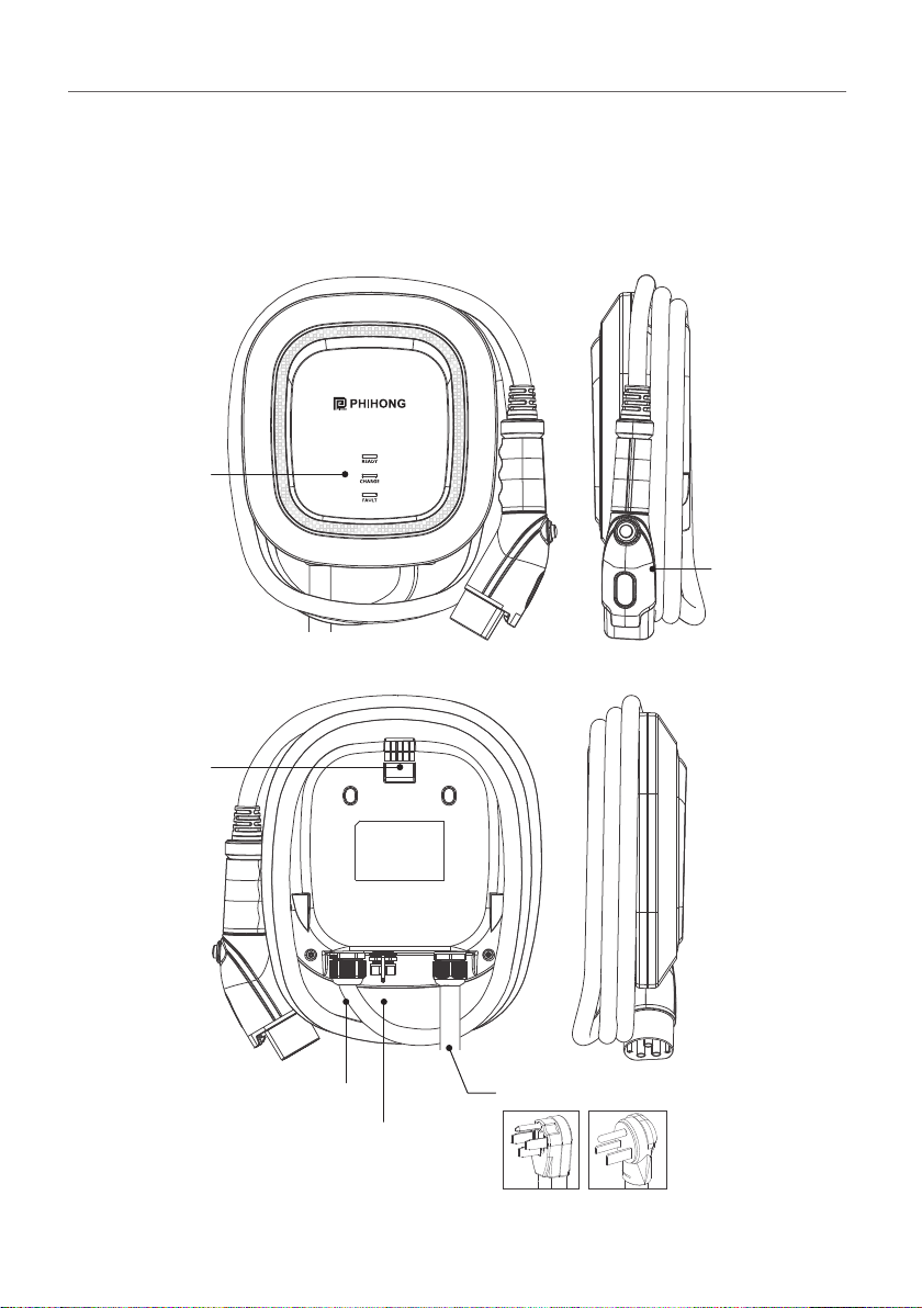
2. Interface
LED Light
Indication
SAE J1772
AC Charging
Connector
2.1 Non-Networking Edition
Rear Notch
Charging Cable Inlet
USB Cable Inlet
AC power cord
14-50 6-50
AW Series - User Manual
3

2.2 Networking Edition
LED Light
Indication
SAE J1772
AC Charging
Connector
Rear Notch
Charging Cable Inlet
USB Cable Inlet
AC power cord
14-50 6-50
RFID
Green Power, Green Lifestyle.
4

3. Dimensions (unit:mm)
3.1 Main Size of Charger
260
280
100
300+50
AW Series - User Manual
5
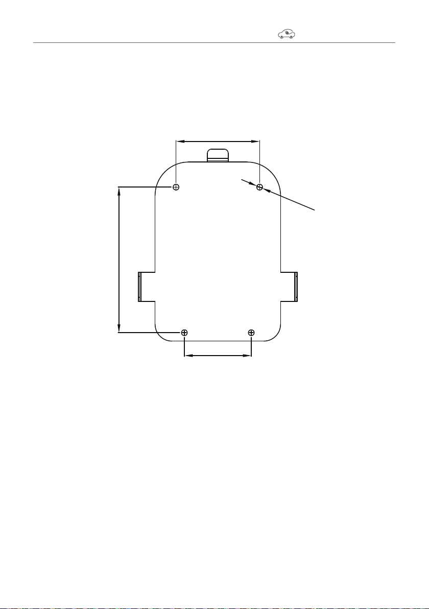
3.2 Wall-Mount Bracket
100
80
174
Ø7x4
Green Power, Green Lifestyle.
6
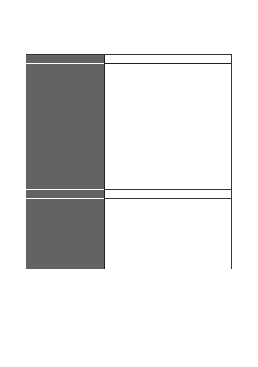
Model Name AW32 UL Version
Rated Input Voltage 200-240 VAC / Single Phase
Rated Output Current Single Phase / 32A
AC Power Frequency 50/60 Hz
Input Protection UVP,OVP,RCD,SPD,Ground Fault Protection
Output Protection OCP,OTP,Control Pilot Fault Protection
Output Interface SAE J1772 AC Charging Connector
Storage Temperature -40°C to + 70°C
Operation Temperature -30°C to +50°C
Relative Operation Humidity 95%RH Maximum
Relative Storage Humidity 95%RH Maximum
RFID Authorization Networking Version or Wi-Fi Version
or 4G Version
RJ45 Cable Inlet*1 10M/100M Base-T
Wi-Fi Function*2 802.11 b/g/n
2G/3G/4G Finction*3 LTE, UMTS/HSPA(+), GSM/GPRS/EDGE
Cable Length 5M (From charger’s body to lower edge of
charging connector)
Protection Level NEMA TYPE 3R
Installation Type Wall-Mounted
Altitude ≤ 2000 m
Weight 4±0.5kg
Dimensions 260mm x 280mm x 100mm
Status Indication Red, Green, Blue LED
4. Specication
*1 Networking Version or Wi-Fi Version or 4G Version
*2 Wi-Fi Version
*3 4G Version
AW Series - User Manual
7

5. Design Standard
Safety standards
UL2594: Electric Vehicle Supply Equipment
UL 2231-1: Personnel Protection Systems for Electric Vehicle (EV) Supply
Circuits: General Requirements
UL 2231-2: Personnel Protection Systems for Electric Vehicle (EV) Supply
Circuits: Particular Requirements for Protection Devices for Use in Charging
Systems
UL 2251: Plugs, Receptacles and Couplers for Electric Vehicles
UL 62: Flexible Cords and Cables
UL 991: Tests for Safety-Related Controls Employing Solid-State Devices
UL 1998: Software in Programmable Components
NFPA 70 Article 625: National Electrical Code, Electric Vehicle Charging System
UL840 (Clearance and Creepage)
Green Power, Green Lifestyle.
8
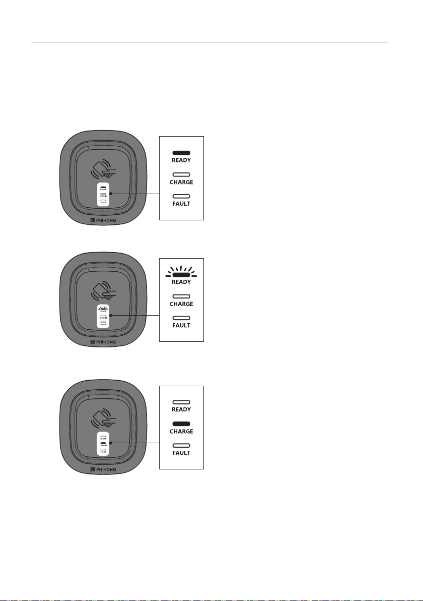
6. Status Description of the Charger
Indication Lights
Standby - Green Light
The READY light stays lit during standby
mode.
RFID Authorization (Internet
Edition)- Green Light Flashing
The Green light is flashing after the RFID
is authorized.
Waiting for Charging - Blue Light
After the vehicle connector is connected
to the vehicle inlet, the CHARGE light is
constantly lit.
AW Series - User Manual
9

Fault - Red Light
The red light is lit during fault. Please
refer to "8.4 Error and Warning
Messages" for detailed information.
Green Power, Green Lifestyle.
10
Charging - Blue Light Flashing
The CHARGE light flashes while
charging.

Safety Requirements
• Read this user manual thoroughly and make sure to review all local
building and electrical codes are reviewed before installing the AC
charger.
• A qualied technician should install the AC charger according to the user
manual and local safety regulations.
• Use appropriate protection when connecting to the main power
distribution cable.
• Type B, C or D breaker with the a rating current of 40Amp should be
installed in the upstream AC distribution box.
• Disconnect switch for each ungrounded conductor of AC input shall be
provided by others in accordance with the National Electric Code, ANSI/
NFPA 70.
7. Installation Instructions
Warning
• Do not use an extension cord, a multi-outlet adapter, a multi-plug, a
conversion plug, or a power strip to plug in the AC charger.
• Do not disconnect the AC charger from the wall outlet when the vehicle is
charging.
• Do not plug the AC charger into a damaged, lose or worn power outlet.
Ensure that the plug on the AC charger t snugly into the wall outlet.
• Do not connect the AC charger into a power outlet that is not properly
grounded.
• If rain falls during charging, do not allow rain water to run along the length
of charge cable, causing the electrical outlet or charging port to become
wet.
• Do not plug the AC charger into an electrical outlet that is submerged in
water or covered in snow. If, in this situation, the AC charger is already
plugged in and needs to be unplugged, turn off the breaker before
unplugging the AC charger.
• Please use a dedicated receptacle with a single socket.
• Verify that the Wall Connector is properly grounded. The Ground
connection must be bonded in the upstream power supply for proper
operation. Check all physical connections, including the wirebox
terminals, electrical panel(s), and junction boxes. In residential power
supplies, check the bond between Ground and neutral at the main panel.
If connected to a step- down transformer, contact the transformer's
manufacturer for direction on how to bond the ground connection.
AW Series - User Manual
11

7.1 Packing List
No. Product Name Quantity Note
1AC Charger (With Charging Cable) 1
2Wall-Mount Bracket 1
3User Manual 1
4Product Certication 1
5Expansion Screw 4
6M6 Self-Tapping Screws 4
7M4 Screw 2
8RFID Card (RFID Version Only) 2
Product Certification
Dateof inspection
Inspector
12345
678
RFID
RFID Version
Green Power, Green Lifestyle.
12

Tools required before installing the charger onto the Wall-Mount
Bracket are:
• Phillips screwdriver for M4 ~ M6
• Voltmeter or digital multimeter (for measuring AC voltage at the
installation site)
• Level ruler
• Pencil or marker
• Machine drill
7.2 Tools and Materials Required
Before installing the wall-mount bracket, you should confirm that
the loading capacity of the wall can reach a weight of 36 kg. When
installing on a cement wall, you can use the included expansion
screw to install the bracket and use a cement drill to drill holes on the
cement wall (Ø8mm)following the spacing in accordance with 3.2.
When installing on a wooden wall, you can directly use the included
M6 self-tapping screws to install the wall-mount bracket and use the
back-mounted backplane to lock and install on the wall directly.
7.3 Wall-Mount Bracket Installation Requirements
7.4 AW Installation Requirements
To select the best location and position to install the wall-mount
unit, you should rst determine the parking position of the vehicle to
ensure the charging connector can be easily inserted into the vehicle
charging inlet.
The Wall-mount unit should be located:
• In a well-ventilated area. Avoid installing in closed boxes or near
the exothermic chargers.
• 1.2 meters or 4 feet above the floor.
• 250mm (10inches) from any obstacles to allow cables to loop
around the wires and related maintenance.
• If in an enclosed garage, on the side of vehicle charging inlet.
AW Series - User Manual
13
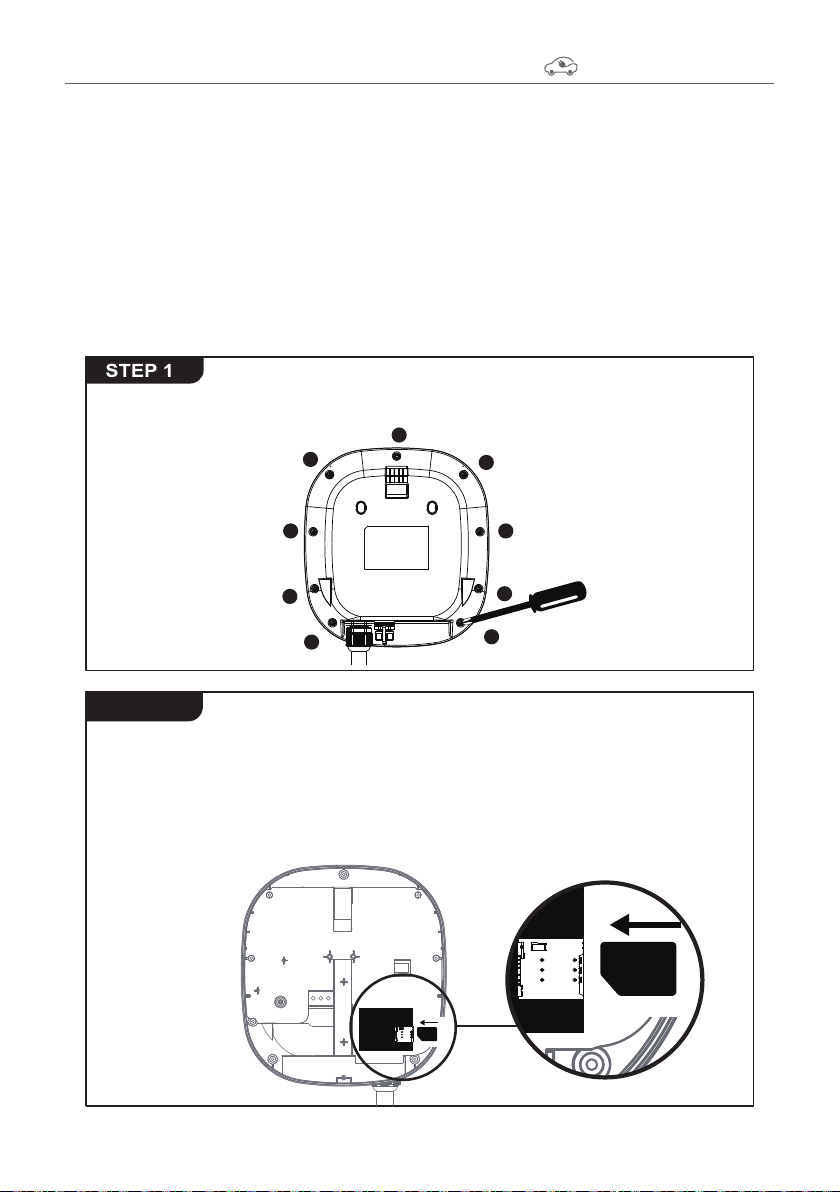
(For Internet Edition model with 4G function)
The SIM card slot is located on the right side. Insert the SIM
card according to the image below.
Important Note: Before installing the SIM card to the charger,
it is necessary to conrm that the SIM card has been activated
and the password has been cancelled.
7.5 4G Installation Steps (4G version)
Use screwdriver to loosen the 9 xed screws on the rear of
charger, then remove the front cover.
�� 1.000
1
2
3
4
5
6
7
8
9
Warning for Wi-Fi and 4G versions:
Due to different congenital environments, it is recommended to first
conduct Wi-Fi and 4G module network signal tests before finalizing
your settings. It is recommended that the RSSI (Received Signal
Strength Indication) value should be higher than-65dBm. If it is lower
than this value,it may result in a weak Wi-Fi or 4G connection or
disconnection due to external interference in the area
STEP 2
Green Power, Green Lifestyle.
14
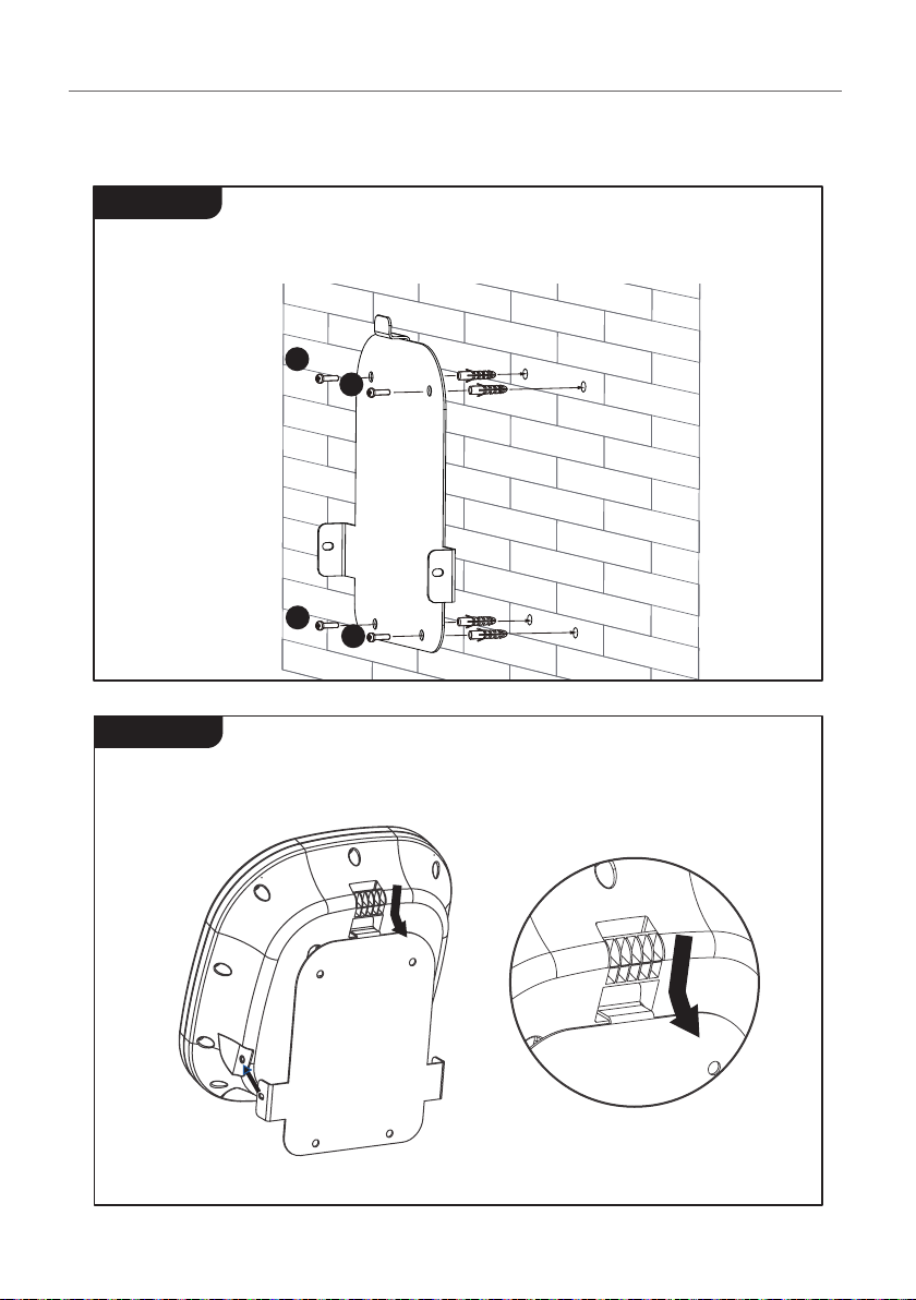
Align the rear notch of charger into the wall-mount bracket and
align the screw holes of the right and left sides.
7.6 Installation Steps
Use the 4 sets of expansion and M6 screws to attach the wall-
mount bracket on the wall.
1
2
34
STEP 2
STEP 1
AW Series - User Manual
15

Attach with the M4 screws to complete the installation.
1
2
Plug the AC Power cord into the power outlet. The AC Power
cord should be inserted completely into the power outlet.
STEP 4
STEP 3
Green Power, Green Lifestyle.
16

Overall outlook picture after installation:
• Wall-mount cable winding • With Optional Cable Hook
(optional accessory)
AW Series - User Manual
17
Other manuals for AW Series
3
This manual suits for next models
1
Table of contents
Other Phihong Batteries Charger manuals


