Phihong EVSE User manual
COPY RIGHT©2018。Phihong Technology reserves the right to make changes to this product without further notice.
EVSE User Manual
P/N: 84A99900078-HE1

1. Important Safety Instructions
2. Basic Interface
3. Main Size of Charger
4. Electrical Specifications
5. Status Description Of The Charger Indicating Light
6. Installation Instructions
6.1 Service Wiring
6.2 Wall-Mounted Installation Requirements
6.3 EVSE Installation Requirements
6.4 Packing list
6.5 Tools and Materials Required
6.6 Installation Steps
7. Operating Instructions
7.1 Operation Procedure
7.2 Operation Steps Description
7.3 Error and Warning Message
7.4 Troubleshooting
8. Maintenance and Repair
8.1 Daily Maintenance
8.2 Maintenance Spares
8.3 Warranty and Maintenance
8.4 Maintenance History
1
3
3
4
5
5
5
6
6
7
8
9
11
11
11
11
11
12
12
12
13
14
Table of Contents

1. Important Safety Instructions
Please read these Important Safety Instructions and the charging instructions in your
vehicle owner’s manual before charging your electric vehicle. Failure to do so can result
in death or serious injury. Save this user guide for future reference. There are many
safety features built into the charger. Read all the safety information and warnings in
this guide to be aware of any hazards and risks associated with using this device.
When using electric products, basic precautions should always be followed, including
the following. This manual contains important instructions that shall be followed
during installation, operation and maintenance of the unit.
•Do not install or use the device near flammable, explosive, harsh, or combustible
materials, chemicals, or vapors.
•Turn off input power at the circuit breaker before cleaning the device.
•The device is designed only for vehicles that are compatible with the SAE J1772
Level 2 charging standard.
•Do not use the device if it is defective, appears cracked, frayed, broken or otherwise
damaged, or fails to operate.
•Do not attempt to open, disassemble, repair, tamper with, or modify the device. The
device is not user serviceable. Contact our Customer Service for any repairs.
•Do not use the device when either you, the vehicle, or the device is exposed to
severe rain, snow, electrical storm or other severe weather.
•When transporting the device, handle with care and do not subject it to strong
force, drag or step on the device.
•Do not touch the charger end terminals with sharp metallic objects.
•Do not forcefully pull the charge cable or damage it with sharp objects.
•Do not put fingers or insert foreign objects into any part of the charging vehicle
connector.
•Using with a worn or damaged AC outlet may cause burns or start a fire.
•Risk of explosion. This device has arcing or sparking parts that should not be
exposed to flammable vapors.
•Risk of electric shock. Do not remove cover or attempt to open the enclosure of the
device. No user serviceable parts inside. Refer servicing to qualified service
personnel.
To reduce the risk of fire, connect only to a circuit provided with 40 amperes maximum
branch circuit overcurrent protection in accordance with the National Electrical Code,
ANSI/NFPA 70, and the Canadian Electrical Code, Part I, C22.1.
1

•This device should be installed, adjusted, and serviced by qualified electrical personnel
familiar with the construction and operation of this type of device and the hazards
involved. Failure to observe this precaution could result in death or severe injury.
• Incorrect installation and testing of the charger could potentially damage either the
vehicle’s battery and/or the device itself. Any resulting damage is excluded of the
warranty for the device.
• Ensure that the EV cable is well positioned during charging, so it will not be stepped on,
tripped over, or subjected to damage or stress.
• Do not use this device with a frayed EV cable which has damaged insulation, or any other
sign of damage.
•Never leave children unattended while the vehicle is charging and never allow children
to play with the EV cable.
• Confirm with the local electrical requirements for the gauge, temperature rating, and type
of wire material used for the overcurrent rating.
• Lockout all electrical source circuit feeding the device in the open position before
beginning wiring or terminations. Failure to follow the instructions could result in severe
bodily injury or death.
Federal Communication Commission Interference Statement
This device complies with Part 15 of the FCC Rules. Operation is subject to the following
two conditions: (1) This device may not cause harmful interference, and (2) this device must
This equipment has been tested and found to comply with the limits for a Class B digital
device, pursuant to Part 15 of the FCC Rules. These limits are designed to provide reasonable
generates, uses and can radiate radio frequency energy and, if not installed and used in
accordance with the instructions, may cause harmful interference to radio communications.
However, there is no guarantee that interference will not occur in a particular installation.
If this equipment does cause harmful interference to radio or television reception, which can
be determined by turning the equipment off and on, the user is encouraged to try to correct
the interference by one of the following measures:
-Reorient or relocate the receiving antenna.
-Increase the separation between the equipment and receiver.
-Connect the equipment into an outlet on a circuit different from that to which the receiver
is connected.
-Consult the dealer or an experienced radio/TV technician for help.
FCC Caution:
Any changes or modifications not expressly approved by the party responsible
for compliance could void the user's authority to operate this equipment.
This transmitter must not be co-located or operating in conjunction with any other antenna
or transmitter.Radiation Exposure Statement:
This equipment complies with FCC radiation exposure limits set forth for an uncontrolled
environment. This equipment should be installed and operated with minimum distance
20cm between the radiator & your body.
Note: The country code selection is for non-US model only and is not available to all US
model. Per FCC regulation, all WiFi product marketed in US must fixed to US operation
channels only.
2

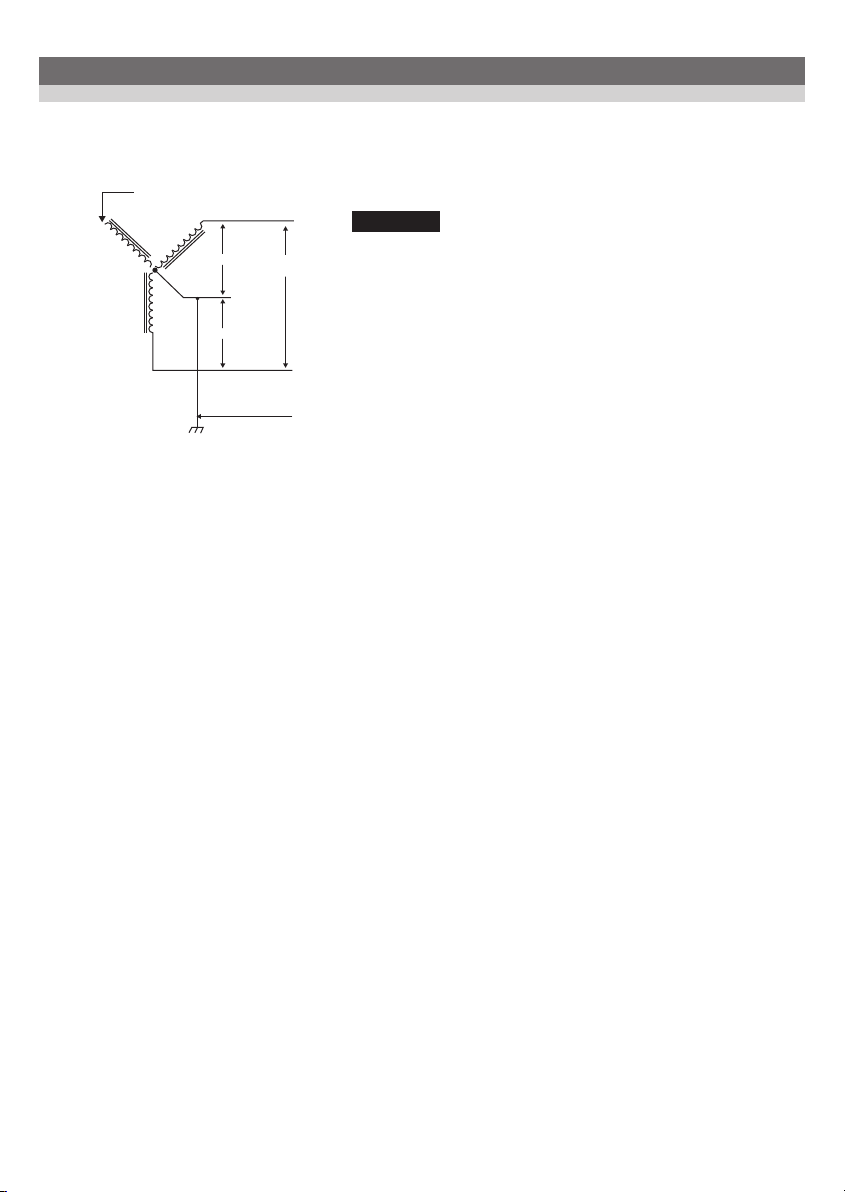
3. Main size of charger (Unit: mm)
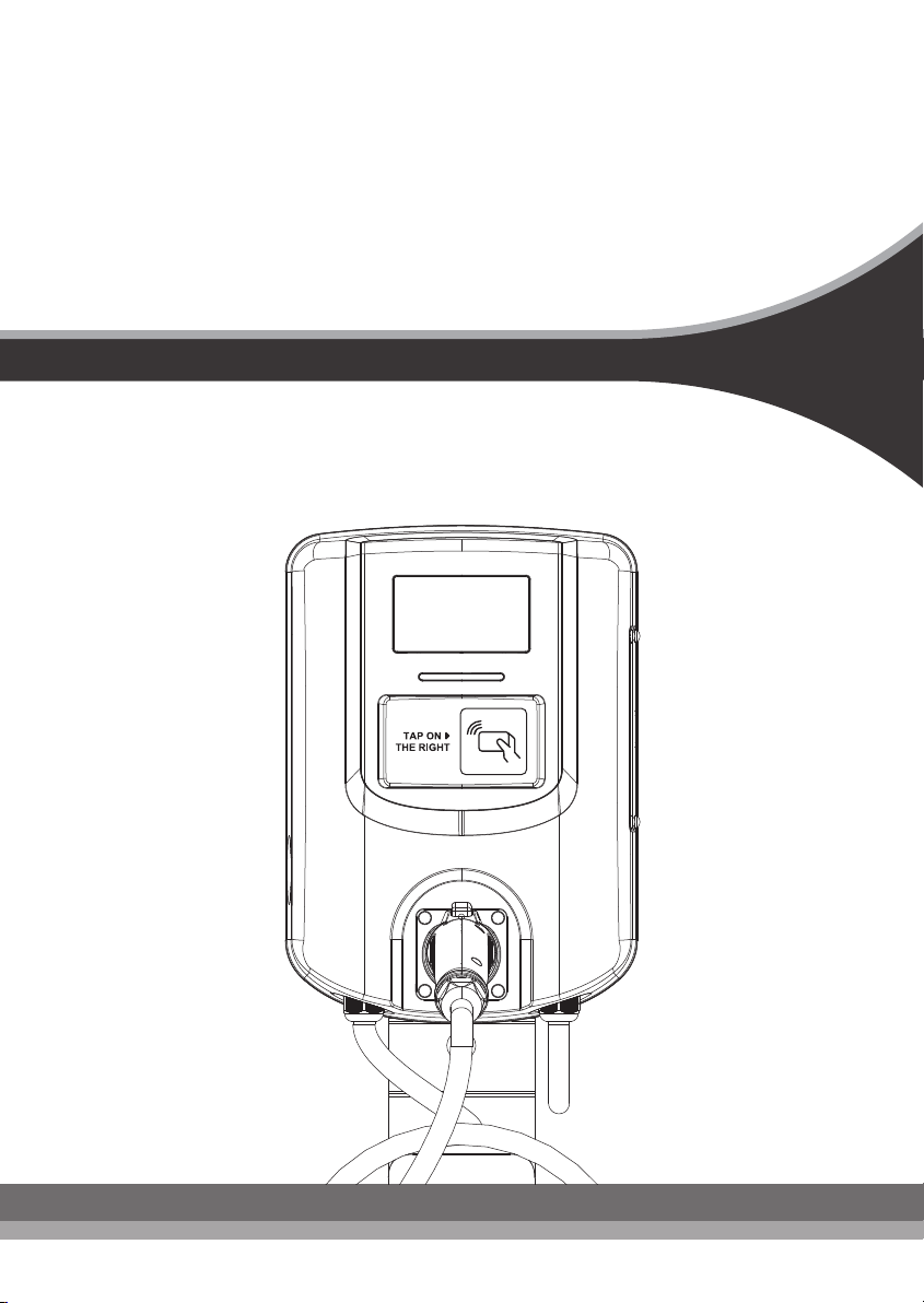
2. EV AC Charger
Emergency button
5” Color LCD
LED light
SAEJ1772
Plug
Indicator breaker
(optional)
3
289
(11.73 in)
409
(16.10 in)
119
(4.86 in)

4. Specification
Product Name
Rated Input Voltage
Rated Output Current
Power Frequency
Ground Protection Detection
Input Side
Output Side
Internal
CCID/RCD
General Charging Requirements
Charging Coupler Connector*
Storage Temperature
Operating Temperature
Relative Humidity of Operation
Relative Humidity of Storage
Communication
RFID
Cable length
Protection level
Installation form
AH32_ EV AC Charger
Model Name EA702C1U
200 - 240VAC / Single phase
32A
50/60Hz
Warning for disconnect input power grounding
UVP, OVP, Residual current detection,
Surge protection, Ground fault
OCP & Pilot fault
OTP, Relay welding detection, MCU function fault detection
CCID 20
SAE J1772
SAE J1772
-40°C to +70°C
-30°C to +50°C
90%RH Maximum
95%RH Maximum
5M
Ethernet 10M/100M(standard),
4G(optional), WiFi(optional)
ISO/IEC 14443A/B, ISO/IEC 15693, Felica™,NFC,Mifare
Mechanism specifications
Electric apparatus characteristics specifications
TYPE 3R
Wall-mounted (standard), stand type (optional)
4

5. Status Description of the Charger Indicating Light
LED Status
Red
Blue Continuous
lighting
Fading out Continuous
lighting
Continuous
lighting
Fading out
Green
Stand-by Charging Charging
Completed Warning
Ready for
Charging
6. Installation Instructions
SAFETY REQUIREMENTS
●
Be sure to preview the standard operating procedures (SOP) and ensure local
building and electrical codes are reviewed before installing the AC charger.
●
The AC charger should be installed by a qualified technician according to the
instruction manual and local safety regulations.
●
Use appropriate protection when connecting to the main power distribution cable.
●
Type B, C or D breaker in the upstream panel should be installed, and the rating
current of the breaker should be 40A.
●
Disconnect switch for each ungrounded conductor of ac input shall be provided by
others in accordance with the National Electric Code, ANSI/NFPA 70.
6.1 Service Wiring
●
240V Single-Phase
120V
120V
240V
L1
L2
GND
NEUTRAL
(NOT USED)
CAUTION!
THE EVSE is a single-phase device. Do not
connect all three phases of a three-phase feed.
The two phases used must each measure 120 V to
neutral. Earth ground must be conneced to
neutral at only one point, usually at the breaker
panel.
5
●
208V Single-Phase
120V
120V
208V
L1
L2
GND
NEUTRAL
(NOT USED)
L3 (NOT USED)
CAUTION!
THE 208V IS FED FROM Y-CONNECTION POWER
GRID, AC CHARGER CAN CONNECT TO L1 AND L2, L2
AND L3, L1 AND L3. EARTH GROUND MUST BE
CONNECTED TO NEUTRAL AT ONLY ONE POINT,
USUALLY AT THE BREAKER PANEL.
6.2 Wall-Mounted Installation Requirements
Attach the bracket using fasteners that are appropriate for the type of wall material,
drilling pilot holes if necessary. Use the supplied screws only if mounting the bracket
directly to a wooden stud. If mounting to another type of wall (hollow, masonry, etc.),
use fasteners that are long enough to securely anchor the Wall Connector and can hold
up to 36 kg.
6.3 EVSE Installation Requirements
Choose the Best Location for the Wall Connector Determine the parking location of the
vehicle to ensure that the charge cable reaches the charge port. The Wall Connector
should be located:
●
In an enclosed garage, typically on the vehicle's charge port side.
●
In a well-ventilated area. Avoid installation in an enclosed box, or adjacent to hot
appliances.
●
4 ft (1.2 m) above the floor.
●
8 in (190 mm) from any obstructions to allow for cable looping.
6

6.4 Packing list
RFID
COPYRIGHT©2018。Phihong Technology reserves the right to make changes to this product without further notice.
Electric Vehicle Service Instruction
EVSE CHARGER
WALL BRACKET
CABLE HOOK
BOTTOM CASE HOOK
BOTTOM CASE HOOK
SCREW M4
SCREW M5
EXPANSION SCREW
KEY
RFID CARD
PRODUCT CERTIFICATION
USER MANUAL
HEX WRENCH T8
No. Content Quantity Remarks
1
1
1
1
2
2
6
4
2
2
1
1
1
❶
❷
❸
❹
❺
❻
❼
❽
❾
❿
⓫
⓬
⓭
Product Certification
Dateof inspection
Inspector
7
⓭

6.5 Tools and Materials Required
Tools required before installing the wall connector, gather the following tools:
●
Pencil or marker
●
Hole punch (optional, to push through cardboard template)
●
Wire stripper
●
Voltmeter or digital multimeter (to measure AC voltage at the installation site)
●
Phillips screwdriver
●
T8 Torx driver
●
Cable Gland information:
1. The AC input cable through hole of Cable Gland is 13~18mm (0.5" ~0.7")
2. If currently cable glands is not suitable to used, please choose a suitable cable
glands.The AC input cable through hole of the EVSE is 28.5mm / 1 “
●
Ferrules (the diameter of the ferrule depends on the diameter of the power wiring
and the construction)
●
Wiring use cable 8AWG (Max diameter: 8.36 mm); Max cross-sectional area:
8.36mm² for a maximum of 15 m between Wall Connectors.
●
Level
●
Machine drill
8
1
8

6.6 Installation steps
1. Select the position of the pile, configure the power and the wall surface
to be applied. Open the back cover and install the AC power cord.
L1-L2 →(Voltage : 208Vac or 240Vac)
L1(Red)
GND (Yellow green)
L2(White)
GNDL1 L2
5-5
8AWG
AC wire
specification
Assemble the back hanger.
1. Use M4 x 2 screws which are numbered 1 to lock. (Fig. 1)
2. Use STP5-32 x 4 expansion screws which are numbered 2, and instal the wall mount
shelf to the mounting wall. (Fig. 1)
3. Fig. 2 showns the installion of the wall bracket. The surroundings around the wall bracket
need to be kept at least 100mm away from the wall bracket.
100
100
100
100
100
200
3
2
•A device employing pressure terminal connectors for field wiring connections shall be provided with
instructions specifying a range of values or a nominal value of tightening torque to be applied to the
clamping screws of the terminal connectors.
•Use No. 8 AWG , 75°C copper wire and 17.7 lb-in (2.0 N-m) Torque force when connecting to I/P Terminal
Block.
2
2
1
2
2
1
(Fig. 1) (Fig. 2)
9

1. Assemble the case hooks.
2. Screw the hooks to the EVSE using M5
x 6 screws.
1. Mount the EVSE on the bracket.
2. During cable installation the space between
the cable and the EVSE shall be more than
18cm.
18cm
1. Turn on the power from the box.
2. Wait for the EVSE to start.
3. When the blue light is on, the EVSE is ready to charge.
10

7. Operating Instructions
7.1 Operation Procedure
●
User authorization
●
Connection to the charging gun
●
Charging message
●
Charging completed
* If you need to authorization an RFID card, you need to connect to
the backend system.
7.4 Troubleshooting
●
If any error messages occur during charging, follow the instructions in the above
table to troubleshoot.
●
If the problem may not be eliminated, please contact the management unit or
contact our Customer Service.
●
During operation, if any emergency needs to be interrupted immediately, press the
emergency stop button on the charger.
7.2 Operation Steps Description (please refer to the insert)
7.3 Error and Warning Message
Item Protected Content Reset Method
Input over voltage Automatic reset.
Input under voltage Automatic reset.
Input power grid grounding
disconnect
Output leakage current self-test
fail
Automatic reset.
Power cycle of AC charger to clear
warning status.
Abnormal connection with
electric vehicle Automatic reset.
Output leakage current over
limit
If this protection function trip, AC
charger will retry charging after 15
minutes and up to 4 times, after
that will latch off. Unplug charging
gun or power cycle of AC charger to
clear warning status.
Output over current Unplug charging gun or power cycle
of AC charger to clear warning status.
1
2
3
4
5
6
7
11

8.1 Daily maintenance
●
Please keep the product clean and keep the product in a clean area with low
humidity. Do not install it in an environment near the sea, with high oil, high
humidity or high dust.
●
Avoid moisture or water in the product. If there is water or moisture in the body, it
is necessary to immediately power off to avoid immediate danger, and notify the
professional personnel to carry out maintenance before next use.
●
If there is any damage or dirt on the charging gun, charging gun cable, or charging
gun holder, please contact the maintenance personnel immediately.
●
Please use the product properly. Do not hit or press hard on the case. If the case is
damaged, please contact a professional technician.
●
Avoid placing the product near hot objects and at high temperature locations, and
away from dangerous substances such as flammable gases and corrosive materials.
●
Do not place external objects or heavy objects on the product (including the power
cord and charging gun cable) to avoid danger.
8.2 Maintenance spares
●
This product is equipped with maintenance spares for maintenance use during and
over the warranty period. All warranty services and repairs shall be and performed
by certified service technicians authorized by Phihong Technology. For details,
please contact your local Phihong Technology service partner or direct to our
Customer Service.
8. Maintenance and repair
12

8.3 Warranty and Maintenance
●
The warranty period for this product is two years parts and labour.
●
Any spare parts provided by Phihong Technology and used as replacements for repair
are covered by a five years guarantee.
●
Replacement and repair parts manufactured by alternative manufacturers to those on
the Maintenance parts are allowed if authorized by Phihong Technology
●
After the event of any repair or maintenance under the warranty period, if there is no
purchase to extend the warranty service, Phihong Technology shall provide a
three-month warranty period for any subsequent paid repair work.
●
During the warranty period for any malfunction caused by normal use according to
the User Manual and Service Instruction (to be determined by certified maintenance
technicians of the Phihong Technology), the product shall be repaired free of charge.
Except for the following situations, the charging device shall be subject to the above
warranty terms:
1. The warranty certificate cannot be provided, or the contents of the warranty
certificate are modified or inconsistent with the label indication of the repaired
product.
2. Those who are unable to provide valid proof of purchase.
3. Those who exceed the manufacturer's specified warranty period.
4. Those who damage the product due to not following the product service
instruction for use, maintenance and storage.
5. Damage or malfunction caused by foreign object entering.
6. Unauthorized repair, disassembly or modification.
7. Damage caused by force majeure (such as lightning, excessive voltage,
earthquake, fire, flood, etc.).
8. Malfunction and damage caused by other unavoidable external factors.
9. Malfunction and damage caused by improper use of equipment, such as water or
other solutions entering into the equipment
10. Malfunction and damage caused by the grid power supply and voltage which is
not specified for use with the charger equipment
●
The above guarantees shall be made solely, and no other express or implied
warranties shall be made (including the implied warranties of merchantability,
particular and applicable reasonableness and adaptability, etc.) whether in the
contract, civil negligence, or other aspects, the Company shall not be responsible
for any special, incidental or consequential damages.
●
This statement is valid only in USA.
13

8.4 Maintenance history
Product name Factory number
Product model
Factory date (month) (day) (year)
Name of Customer
Tel
Address
Maintenance content
After service Signature of Customer
1.
Maintenance content
After service Signature of Customer
2.
Maintenance content
After service Signature of Customer
3.
Maintenance content
After service Signature of Customer
4.
Maintenance content
After service Signature of Customer
5.
14
EA702C1U
Table of contents
Other Phihong Batteries Charger manuals


