Philadelphia Scientific iBOS Pro 6 Series User manual

DOC0505
Installation Manual
iBOS® Pro 6 Series
Battery Manager
Updated October 19, 2022

Philadelphia Scientific® iBOS® Pro 6 Series Installation Manual
Page ii
Table of Contents
iBOS® Pro 6 Series Battery Manager Installation Manual
1. Introduction....................................................................................................................................................1
1.1 System Overview .....................................................................................................................................1
1.2 Organization of Manual ............................................................................................................................1
1.3 Contact Information..................................................................................................................................1
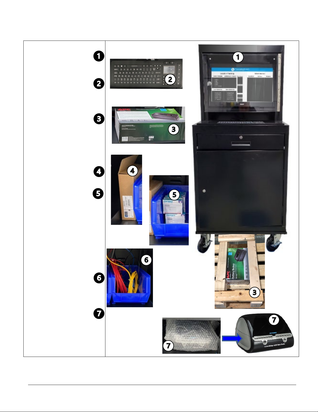
2. System Components......................................................................................................................................2
2.1 Components Received.............................................................................................................................3
3. Pre-Installation...............................................................................................................................................6
3.1 Locate Shipment Pallet ............................................................................................................................6
3.2 Update/verify Existing iBOS® Pro 6 Series System .................................................................................6
3.3 Determine Battery Manager Work Center Location ..................................................................................6
4. Primary System Installation............................................................................................................................7
4.1 Verify Cellular Modem Operation .............................................................................................................7
4.2 Unpack UPS and Set Up..........................................................................................................................7
4.3 Battery Manager & Controller Connections ..............................................................................................7
4.3.1 Black Cable.......................................................................................................................................9
4.3.2 Blue Cable ......................................................................................................................................10
4.3.3 Yellow Cable ...................................................................................................................................11
4.3.4 Red Cable .......................................................................................................................................12
4.4 Battery Manager Barcode Printer Setup.................................................................................................14
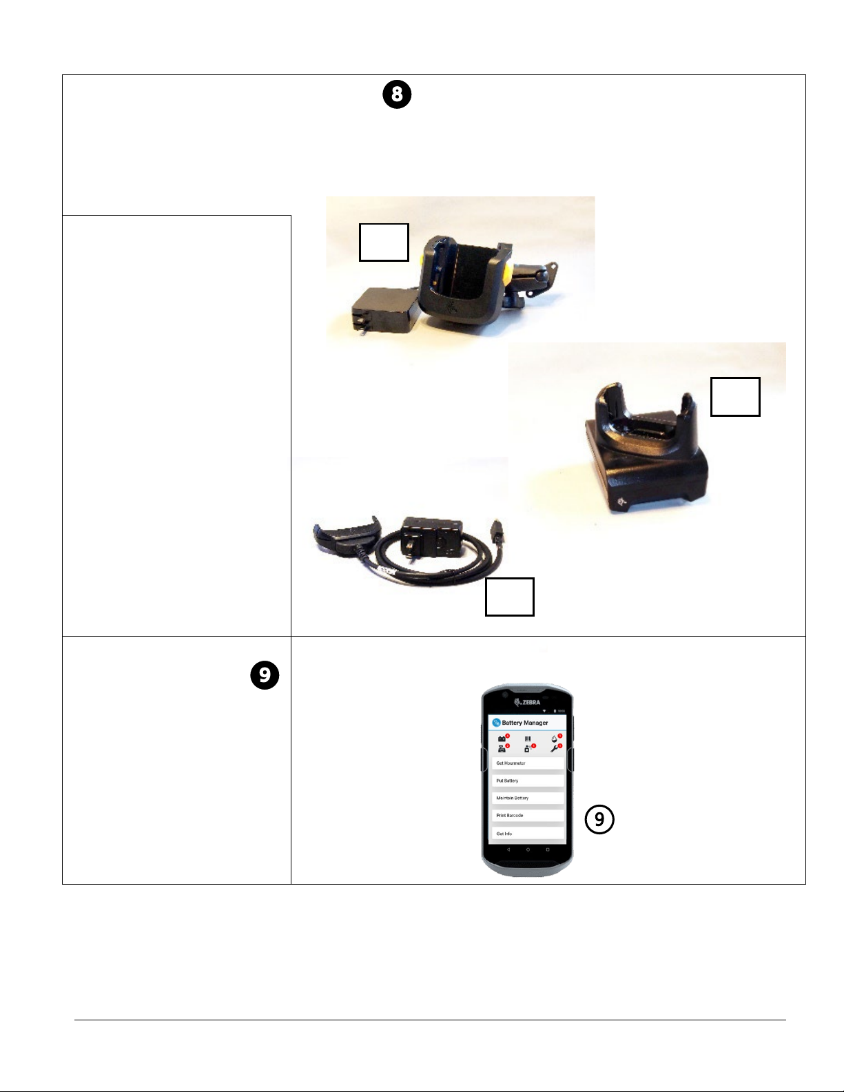
4.5 Installing Touch Computer Cradles ........................................................................................................15
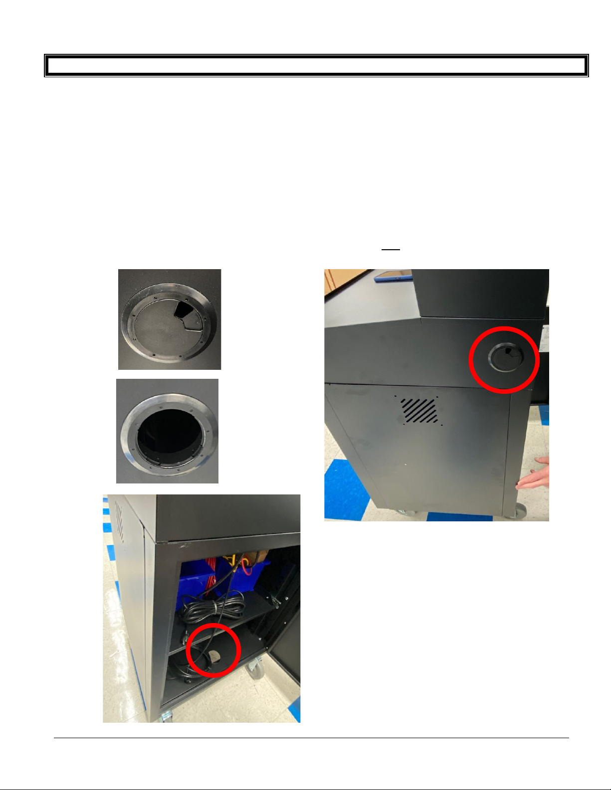
4.6 Plugging in Battery Manager Work Center .............................................................................................15
4.7 Checking Battery Manager Software Version.........................................................................................15
4.8 Starting Battery Manager Touch Computer ............................................................................................16
4.9 Printing Test Barcodes...........................................................................................................................16
5. Barcode Label Installation............................................................................................................................17
5.1 Barcode Printing from the Touchscreen Monitor ....................................................................................17
5.2 Printing and Applying Charger Barcodes................................................................................................17
5.2.1. Printing Charger Barcodes from Touchscreen Monitor: ..................................................................17
5.2.2. Printing Charger Barcodes from Touch Computer: .........................................................................18
5.2.3. Verify and Apply Charger Labels ....................................................................................................18
5.3 Printing and Applying Battery Barcodes .................................................................................................18
5.4 Printing and Applying Truck Barcodes....................................................................................................19
5.5 Printing Battery Barcodes When Assets Pre-Entered.............................................................................20
5.6 Printing Truck Barcodes When Assets Pre-Entered ...............................................................................20
5.7 Asset Registration When Assets Pre-Entered ........................................................................................21
6. Training........................................................................................................................................................25
6.1 Training on Use of Battery Manager.......................................................................................................25
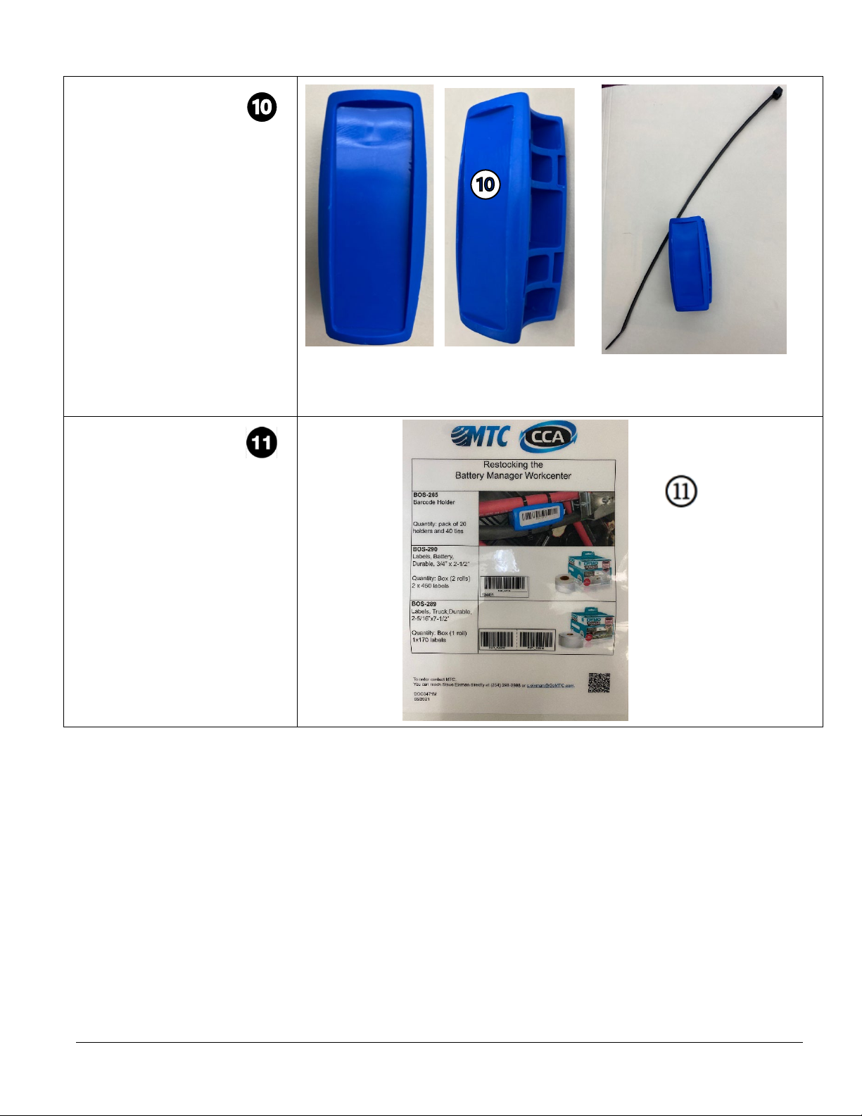
6.2 Remove/Attach Battery Barcode Holder.................................................................................................25
Appendix A. Troubleshooting ..............................................................................................................................I
A.1 Battery Manager Barcode Printer..............................................................................................................I
A.2 Confirmation of Communication on Cell Modem .......................................................................................I
A.3 Confirmation of Proper Operations after Start or Restart of System..........................................................I
A.4 Reference Diagrams and Illustrations .....................................................................................................III

Philadelphia Scientific® iBOS® Pro 6 Series Installation Manual
Page 1
1. Introduction
1.1 System Overview
This manual provides all information needed for a qualified person to install the iBOS® Pro 6 Series. The
purpose for this type of installation is to:
1) Add a Battery Manager to an operational site with an existing iBOS® Pro 6 Series only;
2) Upgrade a Battery Tracker to a Battery Manager at an operational site with an existing iBOS® Pro 6
Series;
3) Add a Battery Manager after adding a new iBOS® Pro 6 Series to an otherwise operational site that
will incorporate these systems together; or
4) Perform an installation of both the Battery Manager and immediately prior the iBOS® Pro 6 Series at
a brand-new facility (i.e., Distribution Center).
This procedure focuses on installation of the Battery Manager specifically, including adding barcodes to all
chargers on the site, and as many battery barcode holders and truck barcode labels as time permits during
installation. In cases where the iBOS® Pro 6 Series is also being installed, refer first to DOC0023 and
associated task documents.
1.2 Organization of Manual
This manual has been divided into each of the stages of an installation project found in the following
Sections:
2. System Components
3. Pre-Installation
4. Primary System Installation
5. Barcode Label Installation
6. Training
Note that pre-installation information prior to work on-site will be managed separately.
1.3 Contact Information
Philadelphia Scientific LLC
207 Progress Drive
Montgomeryville, PA 18936
USA
Phone: 215-616-0390
Fax: 215-616-0500
Email: Info@phlsci.com
Philadelphia Scientific UK Ltd.
Atlas Mill
Bolton BL14LB
United Kingdom
Phone: +44 (0) 1204-
467777
Fax: +44 (0) 1204-
493300
Email: Info@ps-europe.net
Philadelphia Scientific-
Asia/Pacific
2/17 Norman Street
NSW, 2225
Australia
Phone: +61 2 8004-
2447
Fax: +61 2 9012-
0383

Philadelphia Scientific® iBOS® Pro 6 Series Installation Manual
Page 2
2. System Components
This Battery Manager system is composed of two components which communicate with each other and the
iBOS® Pro 6 Series Controller (at left) via hardwire or Wi-Fi (using Wireless Access Point) as indicated
below:
Existing or new components from the iBOS® Pro 6 Series are described separately in DOC0023, which
focuses on that current or previous installation. The largest box contains the already assembled Battery
Manager Work Center (BMWC), and the separate boxes include barcode holders and other accessories.
Use the packing slip to verify the items received, as there may be other items included (e.g., battery
watering systems). The following items are what arrive typically boxed and wrapped onto one pallet when
shipped to the site:
Wired
Battery Manager
Touch Computer
New or Existing
Controller
Battery Manager
Work Center

Philadelphia Scientific® iBOS® Pro 6 Series Installation Manual
Page 3
2.1 Components Received
Battery Manager Work
Center (BMWC)
(shipped with all the following
items):
•Keyboard (in drawer,
nothing to install)
•UPS and Surge
Protector (boxed and
shipped underneath
cabinet on pallet)
•Wireless Access Point
(boxed in lower cabinet)
•Barcode Labels (3
boxes each of wide [2-
5/16" x 7-1/2"] and
narrow [3/4" x 2-1/2"]
barcode labels included
in lower cabinet)
•Red, Yellow, Blue and
Black Cables (attached
at other end to various
Battery Manager
interfaces)
•Barcode Printer
(bubblewrapped and
inserted in lower cabinet)

Philadelphia Scientific® iBOS® Pro 6 Series Installation Manual
Page 4
Touch Computer Cradles
Touch Computer cradles will vary based on what the end user ordered. The primary options appear below;
each cradle provided will come with its manufacturer instructions, and should be installed where the client
has indicated. (These will be packed in the additional boxes.)
Extractor Mounted
ⓐ
Charging Cradle
(typically one or two, depending
on extractors on site)
Desktop Charging Cradle
(typically this OR the Clip-on
Charger below is the additional
item included)ⓑ
Clip-on Charger Cradle ⓒ
Battery Manager Touch
Computer(s)
Handheld with protective case
and hand strap. (This will either
be shipped directly to the
installer to bring to the site; or if
not manufacturer-installed, will
be packed in the cabinet.)
Number of units depends upon
how many ordered.
8a
8b
8c

Philadelphia Scientific® iBOS® Pro 6 Series Installation Manual
Page 5
Barcode Holders
A separate box will be shipped
with the barcode holders (# of
barcode holders determined
client order, typically a
minimum of the asset list
quantity of batteries on site)
and zip ties to be used for
labeling the batteries on site
(sample barcode holder and zip
tie shown).Barcode holders
are typically blue; exceptions
will be noted.
Placards
One card is included (packaged
under the keyboard); this
outlines how to re-order
supplies for the Battery
Manager.

Philadelphia Scientific® iBOS® Pro 6 Series Installation Manual
Page 6
3. Pre-Installation
3.1 Locate Shipment Pallet
An Operations Manager (OM) may have guidance for location and can have pallet brought to Battery Room
if not already there. Verify that all the Battery Manager hardware have been shipped (see list in 2. System
Components and check actual packing list).
3.2 Update/verify Existing iBOS® Pro 6 Series System
When Installing a Battery Manager with an existing iBOS® Pro 6 Series system only:
•Prior to actively starting the Battery Manager, install a new iBOS® Pro 6 Series Controller CF card (see
DOC0252). iBOS® Pro 6 Series may take up to 60 minutes to get the status of all chargers, during
which time the installation team can perform other pre-installation steps.
•Check to ensure there are two new (4G LTE) antennas connected to the cell modem in iBOS® Pro 6
Series Controller, and that they are at least a foot apart from each other and as high above the
Controller as possible. If not, install antennas.
•Check there are no issues with assignment and communication of Sentinels on-site; fix non-reporting or
unassigned Sentinels and perform any Sentinel software upgrades needed.*
•Visually verify that the iBOS® Pro 6 Series Controller is on and running (pools and chargers show up on
iDisplay).
NOTES: If a new iBOS® Pro 6 Series and Battery Manager are being installed at the same time, this step
isn’t needed as installers will be using the DOC0023 concurrently with this manual.
Sometimes a customer with existing system may have already noted a part of the Controller (e.g., iDisplay)
that needs replacement; replacement parts may be included in the installation shipment to complete these
needs during the Battery Manager installation.
*For new systems entirely, ensure Sentinels are installed and running prior to installing Battery Manager.
3.3 Determine Battery Manager Work Center Location
Location considerations, depending on floor layout of Distribution Center, include:
•Keep Battery Room Attendant’s accessibility and safety in mind for location.
•Ensure Battery Manager Work Center (BMWC) near A/C Power (power cord is XX ft.)
•Ensure BMWC placed within 15 ft. of the iBOS® Pro 6 Series Controller.
•Overall BMWC dimensions: 24-1/2"W x 22-1/2"D x 62-3/4"H

Philadelphia Scientific® iBOS® Pro 6 Series Installation Manual
Page 7
4. Primary System Installation
4.1 Verify Cellular Modem Operation
For all sites, iBOS® Pro 6 Series and Battery Manager installations the cellular
modem may be mounted in or outside and above the iBOS® Pro 6 Series Controller.
The modem in Controller should read as follows:
Power — On
Status — Flashing
CD — On
LS — On or Flashing
Signal Strength — 2 or 3 LEDs (bars) On
Avoid mounting antennas near something that could cause
interference (e.g., conveyor with big motor). If determined that there
is not enough signal strength reaching cellular modem, set up signal
amplifier following DOC0520.
4.2 Unpack UPS and Set Up
UPS should be set up according to instructions in box and for ease of
access is most convenient placed on second shelf from bottom of the
Battery Manager Work Center (BMWC) (should be on same shelf as the
barcode printer).
The power cords for the Barcode Printer, and the Touchscreen Monitor and
main computer for system (both located in the backside of the BMWC), get
plugged into the Battery Backup side of the UPS.
4.3 Battery Manager & Controller Connections
Once power has been established as available to the Battery Manager and the cellular modem is operating
properly, connect the Battery Manager cables to the Controller.
Four colored cables with RJ-45 connectors are connected to back panel of BMWC, leading down to the bottom
of BMWC cabinet:
•One ~15 ft. Blue (Cellular Modem)
•One ~15 ft. Black (Controller ENET)
•One ~15 ft. Yellow (Controller REMOTE DISPLAY)
•One 50 ft. Red (Wireless Access Point)

Philadelphia Scientific® iBOS® Pro 6 Series Installation Manual
Page 8
Note on Pulling Cables through Battery Manager Work Center to iBOS® Pro 6 Series Controller:
Minor variations in cabinets for the Battery Manager Work Center (BMWC) do not affect performance; for
bringing the colored cables out from the BMWC to the Controller, the following holes may be observed in the
cabinets upon delivery:
ⓐWhen facing the front of the BMWC, on right side in the middle there is a hole with a removeable
plastic covering. This is typically used to pull the cables through. Sometimes due to convenience and
proximity of the Controller, it is better to have a hole on the left side of the cabinet, so an equivalent one may
be drilled in the similar location.
ⓑWhen facing the back of the BMWC, at the very bottom shelf of the cabinet is also a hole where it is
possible the cables may be pulled through. This method is typically not convenient for cable length or
Controller positioning and is not recommended.
ⓐ
ⓑ

Philadelphia Scientific® iBOS® Pro 6 Series Installation Manual
Page 9
4.3.1 Black Cable
Connecting the iBOS® Pro 6 Series Controller to Battery Manager E-NET Port
•A control box without a Battery Manager
installed yet shows the cell modem is
connected directly to the controller thru
the E-NET port by a short cable (yellow
in this image, may be another color).
Remove this short cable before
proceeding.
(2)
•Using the openings in the
bottom of the Controller
(1), connect the black
cable from the Battery
Manager Work Center (2)
to the ENET port on the
Controller (3).
(3)
(1)

Philadelphia Scientific® iBOS® Pro 6 Series Installation Manual
Page 10
4.3.2 Blue Cable
Connecting the iBOS® Pro 6 Series Controller to Battery Manager E-NET Modem Port
(2)
•Using the openings in
the bottom of the
Controller (1), connect
the blue cable from
the Battery Manager
Work Center (2) to the
E-NET port on the
Cellular Modem (3).
(1)
(3)

Philadelphia Scientific® iBOS® Pro 6 Series Installation Manual
Page 11
4.3.3 Yellow Cable
Connecting the iBOS® Pro 6 Series Controller to Battery Manager: Communications Connection
(3)
Using the openings in the
bottom of the Controller
(1), connect the yellow
cable from the Battery
Manager Work Center (2)
to the Remote Display port
on the Controller (3).
(1)
(2)

Philadelphia Scientific® iBOS® Pro 6 Series Installation Manual
Page 12
4.3.4 Red Cable
Mounting the Wireless Access Point that creates the Battery Manager Wi-Fi network, allowing use of the
Battery Manager Touch Computer.
Using the mounting bracket, mount the
Wireless Access Point in an area
central to the battery room. Mount in as
open an area as possible; if there
must be obstructions, it is better that
they are NOT metal.
Ensure that it is out of reach from trucks
and potential accidents (e.g., a catwalk
or similar area).
•Attach the mounting bracket to a wall or battery rack with appropriate
hardware. Make sure the mounting tab is pointing up.
•If not already connected, connect the RED
cable to the RJ-45 port.
•Before mounting, ensure the BLUE LIGHT is lit on the
Wireless Access Point (if the light is white there is an
issue).

Philadelphia Scientific® iBOS® Pro 6 Series Installation Manual
Page 13
•Set the Wireless Access Point on the
mounting plate as shown and twist to lock.
Depending on where placed, zip ties may
need to be added to secure it.
•Once mounted, ensure the BLUE LIGHT is still lit on the Wireless Access Point
(if the light is white there is an issue).
NOTE: actual placement of Wireless Access Point
must be with blue light part facing downward, like as
shown at right.
•On an installer’s smartphone or computer, go to Wi-Fi and look for the psbattman network. If not available,
ensure Wireless Access Point is connected and there is power to the Battery Manager Work Center
(BMWC).
STOP:
Once confirmed, ensure that
all installers’ smartphones
are now disconnected from
the
psbattman network and
won’t reconnect
automatically.

Philadelphia Scientific® iBOS® Pro 6 Series Installation Manual
Page 14
•Once all four cables are pulled through and
attached from the BMWC to the Controller, add
the slit cable tubing to cover the cables in a
single unit. Once the cable tubing is where
desired, use zip ties on both ends of the tubing to
secure in place.
4.4 Battery Manager Barcode Printer Setup
•Unpack from bubble wrap, ensure USB is set up, then plug
printer power cord into battery backup surge protected part
of UPS. Printer should sit next to UPS on second shelf
from bottom of BMWC.
•Press the form-feed button to eject the labels that protected
the printer during shipment. Open the top cover and
remove any packing material inside the label compartment.
•Remove the label spool from inside the cover and
separate the spool guide from the spindle.
•Hold the spool spindle in your left hand and place the
larger label roll on the spindle so that the labels feed
from underneath and the left edge of the label roll is
firmly against the side of the spool.
*NOTE: Remember the wide barcode labels go on the
left side of the printer and the narrow labels go on the
right side.
•Slide the spool guide onto the right side of the spool
and press the guide tightly against the side of the label
roll, leaving no gap between the roll and the spool.
•Insert the label spool into the slot in the printer cover
with the labels extending from underneath the roll.

Philadelphia Scientific® iBOS® Pro 6 Series Installation Manual
Page 15
Align the left edge of the label with the left edge of the
label feed slot and insert the label into the slot. The
printer automatically feeds the labels, stopping at the
beginning of the first label.
•Repeat this procedure for the smaller roll on the right side of the printer.
•Carefully lower top cover.
4.5 Installing Touch Computer Cradles
Depending on which type(s) and quantity of (charging) cradles were ordered by the client, they will be in
the delivered materials for installation, and should be installed according to the manufacturer’s directions
for each type. The location(s) of cradles should be where the client has indicated they would like them to
be placed. In cases where old scanners are being replaced, first remove the old hardware for any cradles,
etc. from the extractors, Controller, etc. before setting up new cradles.
While waiting for BMWC to boot up, install the Cradle for the Touch Computer on the Battery Extractor(s)
first. Do not place the Touch Computer to charge just yet.
4.6 Plugging in Battery Manager Work Center
Plug the BMWC in to 110 VAC.
4.7 Checking Battery Manager Software Version
•The Touchscreen Monitor in BMWC will start up, and the following screen will eventually
appear, ending in “This is a new install. Do you want to update the site? [Y/N]”

Philadelphia Scientific® iBOS® Pro 6 Series Installation Manual
Page 16
•Once this question appears, contact 215-616-0390 to determine if an updated version of Battery
Manager software is available for download. Do not proceed until this has been done.
4.8 Starting Battery Manager Touch Computer
•Power on the Battery Manager Touch Computer
(button top right).
•If the Touch Computer doesn’t power up, place it in
the cradle.
•The Touch Computer should automatically connect to
the psbattman network and go to the home screen.
Contact Support located in the first section of this manual
if the Battery Manager does not power up.
4.9 Printing Test Barcodes
•On Touch Computer, from home screen select Print Barcode.
•Select one charger barcode, one battery barcode and one truck
barcode to print.
•If unable to print, contact support in first section*.
*See also Battery Manager Printer in Appendix A. Troubleshooting

Philadelphia Scientific® iBOS® Pro 6 Series Installation Manual
Page 17
5. Barcode Label Installation
The Battery Manager system depends on applying unique barcodes to each charger, battery and truck
asset. The first step to set up a site for Battery Manager once the primary system is installed, is to attach
barcode labels. A primary goal of the installation team is to affix barcode labels for all chargers, and as
many battery barcode holders and truck barcode labels that are needed as possible.
For non-upgrade sites only: The preprinted barcoding process enables the Battery Manager system to
quickly begin collecting valuable battery location and charge cycle data, which is needed for tracking
battery maintenance activities such as watering, washing and performing preventative maintenance.
5.1 Barcode Printing from the Touchscreen Monitor
Printing of barcode labels can be
performed here. The following label
types can be printed:
• Charger
• Truck
• Battery
• Area
5.2 Printing and Applying Charger Barcodes
When Battery Manager installation is complete, the site’s charger barcode labels should be all printed then
applied before leaving the site. When the barcode printer was installed during the primary installation
process, single test labels for charger, battery and truck should have already been run.
Charger labels get printed first; Battery Manager uses the chargers that were configured into iBOS® Pro 6
Series. If using the Battery Manager Work Center (BMWC) Touchscreen Monitor, all* charger labels may be
selected to print at once. Note that while barcode labels may be printed from the BMWC Touchscreen
Monitor during the installation process, it can be – and during actual system use it will almost always be –
from the Touch Computer.
*This feature is not available for other labels or from the Touch Computer.
5.2.1. Printing Charger Barcodes from Touchscreen Monitor:
•From home screen at bottom select Print Barcode.
•On next screen select Charger, then the appropriate Pool. A list of chargers in that pool will show.
•Scroll to the bottom of the list of chargers to the option Print all* and select.
•Repeat this step for all Pools.

Philadelphia Scientific® iBOS® Pro 6 Series Installation Manual
Page 18
5.2.2. Printing Charger Barcodes from Touch Computer:
NOTE: The majority of the time, barcodes will be printed from the Touch Computer.
•Power on one Touch Computer and give it 10 minutes to fully receive all asset lists.
•From home screen, select Print Barcode.
•On next screen select Charger, and a list of chargers will show.
•Tap on all the chargers that need labels, then select Print.
5.2.3. Verify and Apply Charger Labels
•Verify barcodes are being printed properly. Note that printing a charger label may take ~18 seconds
each, so that time may be factored when printing an initial set of hundreds of chargers.
•Remove the barcode labels from the
Barcode Printer.
•The installer applies the charger
barcode labels to the rack as shown
here:
5.3 Printing and Applying Battery Barcodes
•To print battery barcodes from either the Touchscreen Monitor or Touch Computer, follow the same
directions as above in 5.2 Printing and Applying Charger Barcodes but select Battery, and
remember there will be no option to Select All for printing.
NOTE: Barcodes default to print two labels for batteries (for each side of the barcode holder if
using), and selecting +or –will increase or decrease the number of barcodes printed.
•Apply battery barcodes on both sides of barcode holders, and/or wherever on batteries it is decided
to place them for best access by the Battery Attendants. More labels may be printed for better
access if desired.
Other manuals for iBOS Pro 6 Series
2
Table of contents