Product Manual
© Philips Ledalite 2011 Page 5
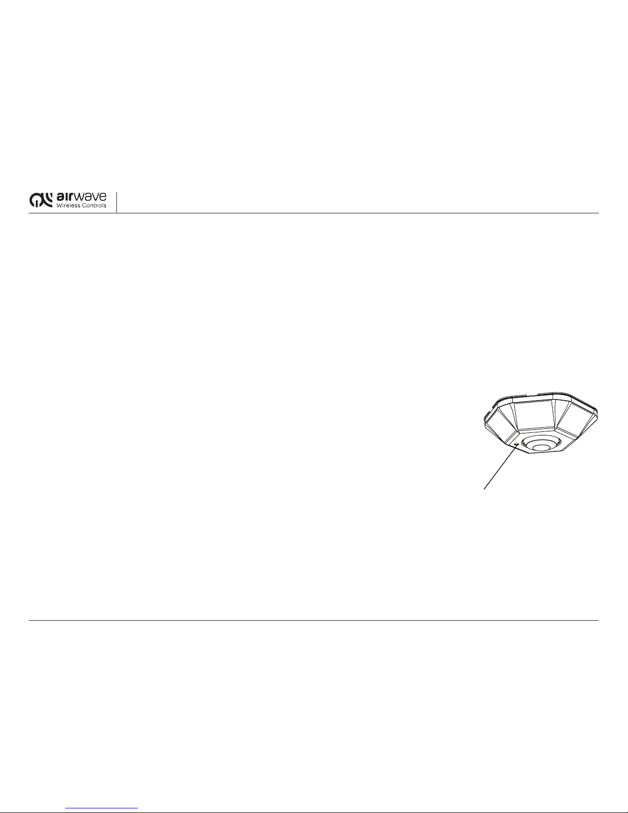
3.0 Solar Powered Wireless Photosensor
TheAirwavephotosensorisabattery-freedevicewhichoperatesonsolarenergyharvestedfromintegralminiaturephotovoltaiccells.Thephotosensoralsotransmitssignalswirelessly.Thisenablesthe
device to be placed anywhere in the space and moved at any time after the initial installation.
ThephotosensormonitorstheambientlightpresentinaspaceandwirelesslytransmitslightlevelstotheAirwavetransceiver.Thetransceiverthenusesthedatatoautomaticallydim,brightenorswitchON/
OFFtheassociatedlights.Forproperclosedloopcontrol,thephotosensorsshouldbelinkedtoonlyonetransceiver,andshouldbelocatedoverthesameareathattheluminairesaremeanttoilluminatewith
aeldofviewthatrepresentsatypicalworksurfaceinthespace(notnecessarilynexttowindows).
Twodifferentsetpointsarestoredinthetransceivermemory;onesetpointfor0-10Vdimmingballasts,andanothersetpointforstandardnon-dimmingballasts.Setpointscanbeeasilychangedbytheuser
andstoredinthetransceivermemory(seeProgrammingGuide).
3.1 0-10V Dimming Ballast Systems
Forluminairesequippedwith0-10Vdimmingballaststhetransceiverreceivessignalsfromthephotosensorandthendims/brightensluminaire(s)inordertomaintainafactorypresetlightlevelof
approximately50fcattheworksurface.LuminairesequippedwithdimmingballastsarenotswitchedOFFbythephotosensorsignal.ThelightingcanbemanuallyloweredusingtheAirwaveSwitch,but
thePhotosensorsetstheupperlightinglevellimitandcannotbeoverridden.Thisensuresthatenergysavingscannotbedisabled.IfthelightlevelisloweredmanuallywiththeSwitch,thelampswillremain
atthatlevelunlessa)thePhotosensorcontrolloopcommandsanevenlowerarticiallightlevel,b)thelamplevelismanuallyraisedbytheSwitchuntilitreachesthePhotosensorcontrolloopsetting,orc)
thelightsareturnedoffandthenbackonagain.
3.2 Standard Non-Dimming Ballast Systems
Photosensor/transceiversystemscontrollingstandardnon-dimmingballastsswitchluminaire(s)ON/OFFbasedonafactorypresetthresholdlightlevelofapproximately
100fcattheworksurface.Thereisafactory-set20%thresholdbetweentheONandOFFtrippointsaswellasatwominuteminimumdelaybetweenON/OFFswitchingtominimizeoccasionswherethe
luminaire would turn on and off in succession as a result of unusual changes in light levels.
Aswithdimmingballasts,theenergysavingscannotbedisabledwithawallswitch.IfthePhotosensorhasturnedthenon-dimmingluminaire(s)off,itcannot
beswitchedbackonmanuallywiththewallswitch.
3.3 Specifications
PowerSource Solarcells-nobatteriesrequired
Measurablelightrange 0-47footcandles(0-510lux)
Minimumlighttocharge 4.6footcandles(50lux)at100secondtransmission(lightlevelnotchanging)
23footcandles(250lux)at10secondtransmission(lightlevelconstantlychanging)
Viewangle Approximately140°
Dimensions 3.9”diameter(100mm),0.9”height(23mm)
Mounting Surfacemountviascrews,tape,glue,etc
OperatingTemperature -25°to+65°C
Wireless Frequency 315 MHz
TransmissionPower Max.10mWEIRP
TransmissionRange 100ftindoor(30.5m)
TransmissionInterval 10secondswhenlightlevelischanging,100secondsotherwise
WirelessTechnology EnOcean
RegulatoryRadio FCC,IC
LinkButton