manuals.online logo
Brands
  1. Home
  2. •
  3. Brands
  4. •
  5. Philips
  6. •
  7. Car Receiver
  8. •
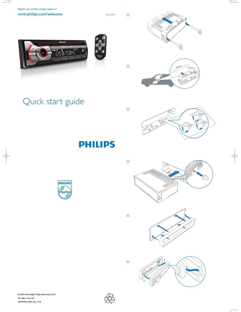
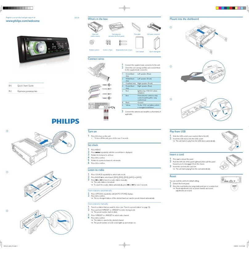
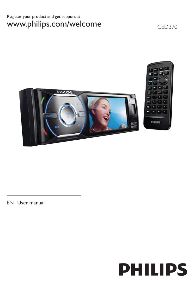
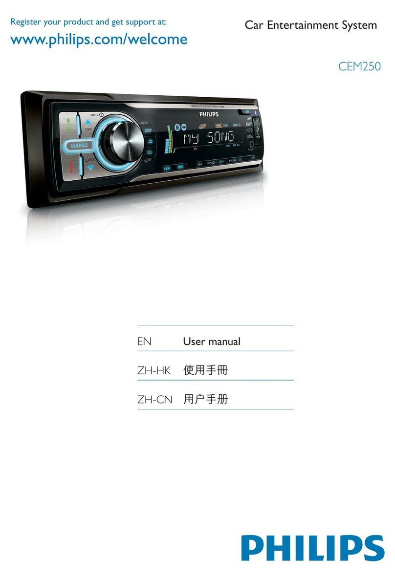
  9. Philips CEM220/51 User manual

Philips CEM220/51 User manual

CEM220/51/55/98
©Copyright 2009 Philips Consumer Electronics B.V. Eindhoven, The Netherlands
All rights reserved. No part of this publication may be reproduced, stored in a retrieval system or
transmitted, in any form or by any means, electronic, mechanical, photocopying, or otherwise without
the prior permission of Philips.
Published by JZ-SL 0948 Service Audio Printed in The Netherlands Subject to modification
Car Entertainment System
Version 1.3
CLASS 1
LASER PRODUCT
3141 785 33213
TABLE OF CONTENTS Page
PCBs Location......................................................................1-1
Specifications .......................................................................1-2
Measurement Setup.............................................................1-3
Service Aids, Safety Instruction, etc.....................................1-4
Instructures on CD Playability ....................................1-5 to 1-6
Disassembly Diagrams...............................................2-1 to 2-2
Software Version Check & Upgrade.....................................3-1
Malfunction Check Chart......................................................3-2
Set Block Diagram................................................................4-1
Set Wiring Diagram ..............................................................5-1
Main Board..............................................................................6
Servo Board.............................................................................7
FB/USB Board.........................................................................8
SD Board.................................................................................9
Key Board..............................................................................10
Set Mechanical Exploded View & Parts List.......................... 11
CEM220X/78
Revision List.......................................................................... 12
2
2
C C
C C
CC
/98
/98
C
C
C/M
C
C/M
/51
FRONT
KEY
CONNECTION (CB BOARD) C/M
C/M
C/M
C/M
C/M
C/M
C/M
C/M
C/M
C/M
FRONT KEY
SPECIFICATIONS
1-2
Components
Note: Specifications and design are subject to change
without notice for product improvements.
Car audio system
Remote control
Rubber cushion
Disassembly tool
Front panel
Carrying case for front panel
Trim plate
Screw
User manual
Quick start guide
1
1
1
2
1
1
2
4
1
1
General
Radio
Power supply:
Fuse:
Suitable speaker impedance:
Maximum power output:
Continuous power output:
Pre-Amp output voltage:
Subwoofer output voltage:
Aux-in level:
Dimensions(W×H×D):
Wight:
12V DC(11V-16-),
negative ground
15V
4-8Ω
45W×4channels
22W×4channels(4Ω10%
T.H.D)
2.0V(USB play mode;
1kHz,0dB,10kΩ load)
2.0V(USB play mode;
61kHz,0dB,10kΩ load)
≥500mV
188×58×128MM
1.0kg
Frequency range
-FM
Frequency range
-AM(MW)
Usable sensitivity
-FM
Usable sensitivity
-AM(MW)(S/N=20dB)
Frequency response
Stereo separation
Signal/noise ratio
87.5-108.0MHz(Eur)
87.5-107.9MHz(Ame)
522-1620kHz(Eur)
530-1710MHz(Ame)
8uV
30uV
30Hz-15kHz
30db(1kHz)
>55dB
MEASUREMENT SETUP
Tuner FM
DUT
RF Generator
Bandpass
LF Voltmeter
e.g. PM5326
250Hz-15kHz
e.g. 7122 707 48001 e.g. PM2534
S/N and distortion meter
e.g. Sound Technology ST1700B
Ri=50Ω
Use a bandpass filter to eliminate hum(50Hz,100Hz) and disturbance from the pilottone(19kHz,38kHz).
Tuner AM (MW,LW)
DUT
RF Generator
Bandpass
LF Voltmeter
e.g. PM5326
250Hz-15kHz
e.g. 7122 707 48001 e.g. PM2534
S/N and distortion meter
e.g. Sound Technology ST1700B
Ri=50Ω
Frame aerial
e.g. 7122 707 89001
To avoid atmospheric interference all AM-measurements have to be carried out in a Faraday s cage.
Use a bandpass filter ( or at least a high pass filter with 250Hz) to eliminate hum ( 50Hz,100Hz ).
'
DUT DUT
L
R
LF Generator
e.g. PM5110
LEVEL METER
e.g. Sennheiser UPM550
with FF-filter
S/N and distortion meter
e.g. Sound Technology ST1700B
L
R
LEVEL METER
e.g. Sennheiser UPM550
with FF-filter
S/N and distortion meter
e.g. Sound Technology ST1700B
Use Audio Signal Disc SBC429 4822 397 30184
(replaces test disc 3)
Cassette
Use Universal Test Cassette CrO2 SBC419 4822 397 30069
or Universal Test Cassette Fe SBC420 4822 397 30071
CD
1-3
1-4
SERVICE AIDS
GB
GB
WARNING
All ICs and many other semi-conductors are
susceptible to electrostatic discharges (ESD).
Careless handling during repair can reduce life
drastically.
When repairing, make sure that you are
connected with the same potential as the mass
of the set via a wrist wrap with resistance.
Keep components and tools also at this
potential.
ESD
CLASS 1
LASER PRODUCT
Safety regulations require that the set be restored to its original
condition and that parts which are identical with those specified,
be used
Safety components are marked by the symbol !.
Lead free
1-5
INSTRUCTIONS ON CD PLAYABILITY
Set remains closed!
check playability
N
N
N
Y
Y
Y
check playability
Exchange CDM
"fast" lens cleaning
playability
ok?
playability
ok?
playability
ok?
①
Customer complaint
"CD related problem"
Check playability
Play a CD
for at least 10 minutes
ann lnfo for customer
"SET OK"②
return set
①-④For description-see following pages
③
For flap loaders(=access to CD drive possible)
clesning method④is recommended
1-6
2-1 2-1
Disassembly Diagram
1
2
3
4
567
1. Remove the mounting sleeve with the removal keys.
Press key and remove the front panel.
2. Remove the two screws on the back side of
the unit with a screw driver.
4. Remove the screw 3 as shown. 5. Remove the bottom cover with a tool.
3. Remove the upper cover with a tool.
6. Remove the screws 4 with a screw driver.
7. Remove the screw 5 with a screw driver. 8. Remove the connectors 6, and then remove
the mechanism core.
9. Remove the adhesive tapes 7.
12
11
10
2-2 2-2
Disassembly Diagram
8
9
10. Remove the screw 8 . 11. Remove the screw 9 . 12. Remove the screw 10 .
13. Remove the connectors 11, and then remove
the bracket with a tool.
14. Remove the screws 12.
3-1 3-1
Software version check & upgrade Upgrade software
VS-104
1、Check Servo software version
2、Check MCU software version
3、Check BT software version
VM-103
VBT-177
In USB/SD/Disc mode, press DISP + 6 simutaliously
for 2 sec, LCD display is as below:
In tuner mode, press DISP + 6 simutaliously for 2 sec,
LCD display is as below:
In tuner mode, press DISP + 5 simutaliously for 2 sec,
LCD display is as below:
102 is the servo software version
101 is the MCU software version
177 is the MCU software version
1、Copy servo software "BOOT.ALI" and "nemo.bin" into USB memory,
plug the USB memory into USB socket.Device upgrade servo software
automatically,Don't power off or disconnect power during the upgrade,
LCD show:
SERVO UPGRADING,,,DON'T PWR OFF
Around 1 minute,servo software upgrade completed and device change
to radio mode automatically
2、Delete the servo software in the USB and copy the MCU software
"CEM250MCU" (for CEM250) into USB memory, plug the USB memory
into USB socket.Device upgrade MB software software automatically
Don't power off or disconnect power during the upgrade, LCD show:
Around 1 minute,MB software upgrade completed and device power
off automatically,disconnect the USB memory.
MCU UPG
3-2 3-2
Malfunction check chart
Check power wirt,
speaker wire is
fasten or not
Fix the wire
TDA7386 of AMP
Change the r
components
Powe
CD display
Check 5673 ALI
circuit and its
conjoint part
Check CD output
Components
Check tuner circuit
and is conjoin part
is good or bad
Change the tuner
Check cd whether rand
disc,and its functions
whether connect to USB
CD no
sound
Check CD control
circuit is good or bad Change components
of CD circuit
CD
Check the related
components of CD signal
channel,cable,socket is
good or bad
4-1 4-1
SET BLOCK DIAGRAM
5-1 5-1
WIRING DIAGRAM
DO NOT connect any speaker wires
to the metal body or chassis of the
vehicle. DO NOT connect the speaker
common (-) wires to each other. Conn-
ect each speaker wire directly to each
speaker terminal. All speaker common
(-) wires must remain floating.
Connector
1 3 5 7
2 4 6 8
1 3 5 7
2 4 6 8
A
B
FUSE
B
A
Black
Yellow
Red
Blue
Brown
Ground Lead
Ignition key+12V DC When ON/ACC
To car battery(+) Continuous +12V DC
Motor/Electric Antenna relay control Lead
Amplifier relay control Lead
Illumination/brown
White/
Black
Stripe
White
Gray/
Black
Stripe
Green/
Black
Stripe
Gray Green
Purple/
Black
Stripe
Purple
Left Speaker
(Front)
Left Speaker
(Rear)
Right Speaker
(Front)
Right Speaker
(Rear)
A1 A2 A3 A4 A5 A6 A7 A8
B1 B2 B3 B4 B5 B6 B7 B8
15 A
Rear line Out L
Rear line Out R
SUB OUT
ANTENNA
MIC(CEM250 only)
6-1 6-1
MAIN BOARD-CIRCUIT DIAGRAM
6-2 6-2
MAIN BOARD-PCB LAYOUT TOP/BOTTOM VIEW
7-1 7-1
SERVO BOARD-CIRCUIT DIAGRAM
7-2 7-2
SERVO BOARD-LAYOUT DIAGRAM TOP/BOTTOM VIEW
8-1 8-1
CB/FB/USB BOARD-CIRCUIT DIAGRAM
8-2 8-2
CB BOARD-PCB LAYOUT TOP/BOTTOM VIEW
8-3 8-3
FB BOARD-PCB LAYOUT TOP/BOTTOM VIEW

Other manuals for CEM220/51

2

This manual suits for next models

3

Other Philips Car Receiver manuals

Philips CED780 User manual

Philips

Philips CED780 User manual

Philips CEM2101/10 User manual

Philips

Philips CEM2101/10 User manual

Philips CE152/10 User manual

Philips

Philips CE152/10 User manual

Philips CE120 User manual

Philips

Philips CE120 User manual

Philips CEM5100/00 User manual

Philips

Philips CEM5100/00 User manual

Philips CEM3000X/78 User manual

Philips

Philips CEM3000X/78 User manual

Philips CEM2250/51 User manual

Philips

Philips CEM2250/51 User manual

Philips CED1900BT User manual

Philips

Philips CED1900BT User manual

Philips CEM200/98 User manual

Philips

Philips CEM200/98 User manual

Philips CMD310 User manual

Philips

Philips CMD310 User manual

Philips CEM2000/51 User manual

Philips

Philips CEM2000/51 User manual

Philips CED230/51 User manual

Philips

Philips CED230/51 User manual

Philips CED1700 User manual

Philips

Philips CED1700 User manual

Philips CarStudio CEM2101R/51 User manual

Philips

Philips CarStudio CEM2101R/51 User manual

Philips CEM2090 User manual

Philips

Philips CEM2090 User manual

Philips CEM220 User manual

Philips

Philips CEM220 User manual

Philips CED1700/00 User manual

Philips

Philips CED1700/00 User manual

Philips CEM2100 User manual

Philips

Philips CEM2100 User manual

Philips CE152 User manual

Philips

Philips CE152 User manual

Philips CEM2101R User manual

Philips

Philips CEM2101R User manual

Philips CEM3000B User manual

Philips

Philips CEM3000B User manual

Philips CED229/56 User manual

Philips

Philips CED229/56 User manual

Philips CED780/51 User manual

Philips

Philips CED780/51 User manual

Philips CEM3000 User manual

Philips

Philips CEM3000 User manual

Popular Car Receiver manuals by other brands

Panasonic CQ-5800U - Double DIN Heavy Duty MP3 Service manual

Panasonic

Panasonic CQ-5800U - Double DIN Heavy Duty MP3 Service manual

Clarion DUZ388RMP owner's manual

Clarion

Clarion DUZ388RMP owner's manual

Eclipse E-iSERV CD3200 Handy Reference Guide

Eclipse

Eclipse E-iSERV CD3200 Handy Reference Guide

Kenwood KDC-348U instruction manual

Kenwood

Kenwood KDC-348U instruction manual

Aiwa CT-R411 Service manual

Aiwa

Aiwa CT-R411 Service manual

JVC KD-HDR20 instructions

JVC

JVC KD-HDR20 instructions

JVC KD-SX740J Installation & connection manual

JVC

JVC KD-SX740J Installation & connection manual

Sound Storm ML44USA user manual

Sound Storm

Sound Storm ML44USA user manual

Blaupunkt 7 647 482 310 operating instructions

Blaupunkt

Blaupunkt 7 647 482 310 operating instructions

Akai ACR-127MMC Service manual

Akai

Akai ACR-127MMC Service manual

Pioneer DEH-X8550BT owner's manual

Pioneer

Pioneer DEH-X8550BT owner's manual

LG LAC6700RP owner's manual

LG

LG LAC6700RP owner's manual

Jensen Audio DV-7780 Service manual

Jensen Audio

Jensen Audio DV-7780 Service manual

Pioneer XDV-P6 - DVD Changer - in-dash installation manual

Pioneer

Pioneer XDV-P6 - DVD Changer - in-dash installation manual

Pyle PLCD82MP instruction manual

Pyle

Pyle PLCD82MP instruction manual

Audiovox XMCommander XM-RVR-FM-001C user manual

Audiovox

Audiovox XMCommander XM-RVR-FM-001C user manual

JVC EXAD KW-AVX810 Installation & connection manual

JVC

JVC EXAD KW-AVX810 Installation & connection manual

Aiwa CDC-R707M Service manual

Aiwa

Aiwa CDC-R707M Service manual

manuals.online logo
manuals.online logoBrands
  • About & Mission
  • Contact us
  • Privacy Policy
  • Terms and Conditions

Copyright 2025 Manuals.Online. All Rights Reserved.