Philips Showline MCP9350I User manual

MediaCenter PC Model
©
Copyright 2005 Philips Consumer Electronics B.V. Eindhoven, The Netherlands.
All rights reserved. No part of this publication may be reproduced, stored in a
retrieval system or transmitted, in any form or by any means, electronic,
mechanical, photocopying, or otherwise without prior permission of Philips.
Published by Philips Applied Technologies Printed in the Netherlands
Subject to modification EN 0000 000 00000
MCP9350i
Service Manual
Contents Page Contents Page
1. About this Manual 2
2. Safety Instructions, Warnings and Notes 3
3. System Overview 4
4. Technical Reference 5
5. Required Equipment List 10
6. Diagnosis and Repair Flowchart 11
7. Installation and Initial Checks 12
8. Troubleshooting - Start-up Failure 15
9. Software Update and Repair 16
10. PC Doctor Diagnostic Tool 20
11. Hardware Tests 22
12. Hardware Repair 38
13. Software Re-installation 64
14. End Test 65
15. Parts Information 66

EN 2 1. MCP9350i About this Manual
1. About this Manual
1.1. Content of this Manual
Note: The MCP9350i will be serviced on a modular level only. Faulty modules will be identified and replaced. Detailed circuit
diagrams and technical information on a component level are therefore not provided in this document.
1.1.1. What is included in this Manual
• Safety Information
• System Overview
• Basic System Block Diagrams
• Parts / Module Identification
• Module Functional Descriptions
• Basic Module Technical Descriptions
• Basic Measuring Point Information
• Basic Fault Finding Strategy
• Module Removal & Replacement Procedures
• Functionality Testing Procedures
• End Test Sequence / Checklist
• Parts List / 12NC Numbers
1.2. Additional Documentation
The following documentation is supplied by Philips and can be used for further reference.
• MCP9350i Quick Install Guide
• MCP9350i Use Cases
• RC4370 Remote Control User Manual

Safety Instructions, Warnings and Notes MCP9350i 2. EN 3
2. Safety Instructions, Warnings and Notes
2.1. Safety Instructions
2.1.1. ESD Protection
All ICs and many other semi-conductors are susceptible to electrostatic discharges (ESD). Careless handling during
repair can reduce life drastically. When repairing, make sure that you are connected with the same potential as the
mass of the set via a wrist wrap with resistance. Keep components and tools also at this potential.

EN 4 3. MCP9350i System Overview
3. System Overview
3.1. Technical Specification
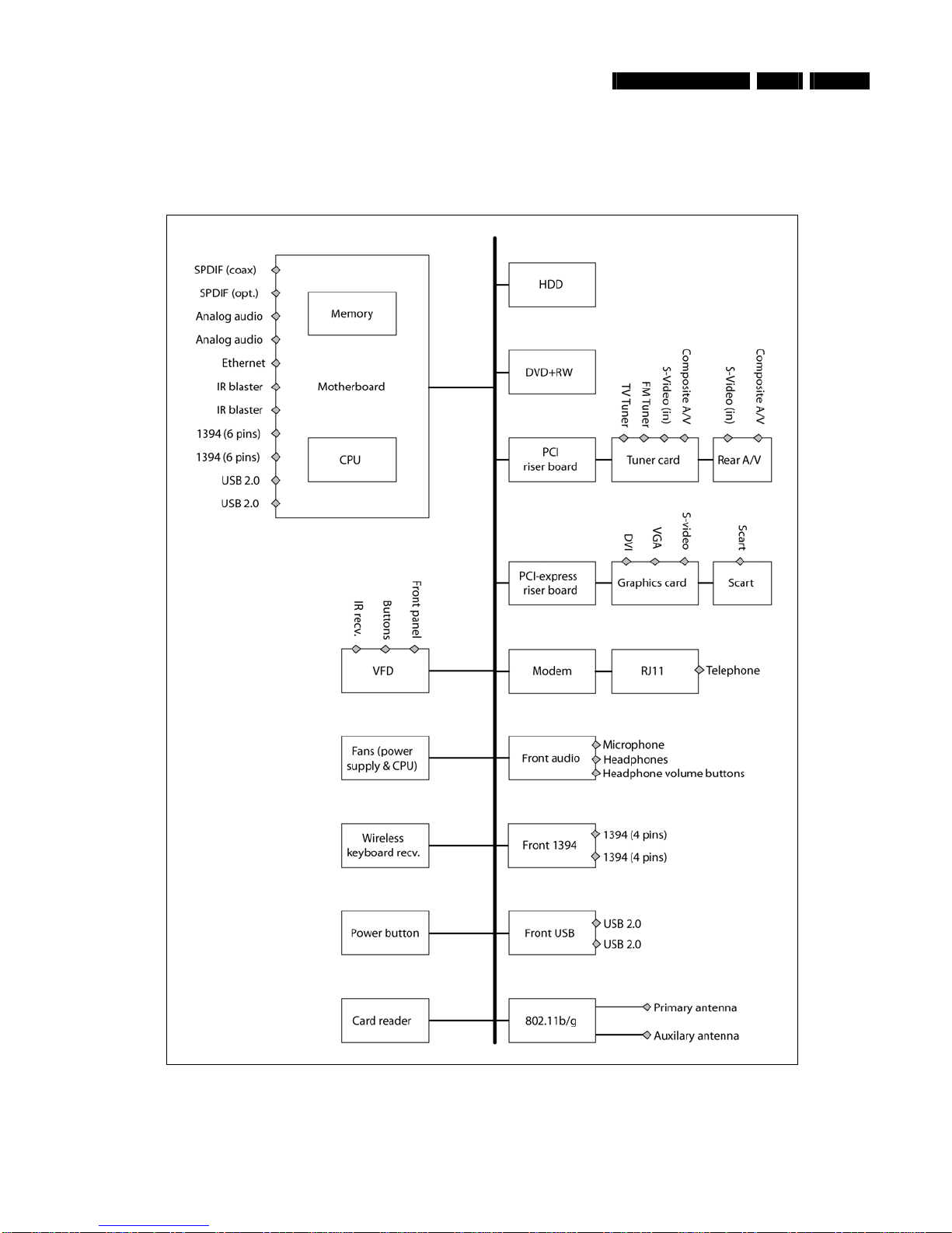
System - General Connection rear
CPU: 3.0 GHz P4 (630) Video outputs: DVI-D single link
Memory: 512 MB VGA
HDD: 250 GB SATA S-video (Y/C)
SCART (CVBS + RGB)
Optical disc recording:
DVD: +RW, +R, -R, -RW, +R DL Video Inputs: 2 x S-video (Y/C)
CD: -R, -RW 2 x CVBS
Wireless LAN: IEEE802.11 b/g Audio outputs: 2x stereo Chinch L/R
Optical digital out
Software installed: Coax digital out
Windows® XP Media Center Edition
LikeMusic Audio inputs: 2x stereo Chinch L/R
Norton Internet Suite Ethernet: 1x (100 Mb)
Cyberlink: Make DVD, CaptureDV, PowerDVD Modem (built in): 1x RJ45
Picture improvement: Trimension MCE USB: 2x USB 2.0
Philips Media Manager IEEE1394: 2x 6 pins
IR blaster: 2x to support up to 3 IR blaster eyes
Picture Improvement algorithms: Others: TV in
Digital Natural Motion FM radio in
Motion adaptive de-interlacing Film mode detector
Tuner card: NVIDIA
TV system: PAL/SECAM Accessories
DVI to DVI cable
DVI to HDMI cable
Connection front SCART cable
Card reader: MS/MS pro (Memory Stick) Digital audio coax cable
CF I/II Microdrive (Compact Flash) Power cable
Smart Media FM antenna cable
MMC/SD (Multi Media Card/Secure Digital) S-video (Y/C)
USB 2x USB 2.0 Stereo audio cable
IEEE1394 1x 4 pins (i.LINK) Ethernet cable
Microphone 6.3 mm jack Telephone cable
Headphone 6.3 mm jack 2x IR blaster with 1 IR transmitter
TV antenna splitter
Antenna cable 10 cm
Antenna cable 1 m
SCART adapter (SCART to CVBS/S-video (Y/C))
Audio L/R Chinch
Universal remote control with batteries
Wireless keyboard with batteries

Technical Reference MCP9350i 4. EN 5
4. Technical Reference
4.1. System Block Diagram
Figure 4.1-1

EN 6 4. MCP9350i Technical Reference
4.2. System Cable Definition
4.2.1. System Cable Schematic
J8H1
FP_AUDIO
J5A2 J8A2
JAUDIO1
FP_1394
FP_USB
Cable 1
Cable 2
Cable 3
FP I/O Board
PCI Riser TV Tuner Card
PCI Bus
PCI Bus
TV Daughter Card
JFP1 JJFP2
VFD Board
JUSB1 J2
J9H1 J6A1 J9C2 J7A2 SATA EIDE
-
A
V2
PCI-E Riser Graphics Card
PCI-E Bus
PCI-E Bus
Cable 12
SCART Daughter Card
-
-
Cable 11
SW Board
Card Reader
JRF1
Cable 4
Cable 5
JFP1
-
JRF2
Cable 6
MD RJ-11 Board
RF Board
Cable 7
MD Card
MDC
-
-
HDD
SATA
ODD
EIDE
Cable 8
Cable 9
Cable 10
MOTHERBOARD
Front panel
Front panel
Front panel
Rear panel Rear panel
Rear panelRear panel
Rear panel
Figure 4.2-1

Technical Reference MCP9350i 4. EN 7
4.2.2. System Cable Definition Table
Cable
Number Cable Name Start End(s)
1 FP_AUDIO_CABLE MB J8H1 FP BOARD JAUDIO1
2 FP_1394_CABLE MB J5A2 FP BOARD JFP1
3 FP_USB_CABLE MB J8A2 FP BOARD JFP2
4 VFD_USB_CABLE MB J6A1 VFD Board JUSB1
5 IR_BLASTER_INTERNAL_CABLE MB J9C2 VFD BOARD J2
6 SW_RF_CABLE VFD Board JRF1 SW BOARD JRF2
7 V-TYPE_CABLE MB J7A2 (1) SW BOARD JFP1
(2) CARD READER
8 SATA_HDD_CABLE MB J7F1 HDD
9 ATA33_ODD_CABLE MB EIDE ODD
10 MD_CABLE MB MD CARD MD RJ-11 CONNECTOR BOARD
11 ADD2_SCART_CABLE MB J9H1 (1) ADD2 SCART DAUGHTER CARD
(2) GRAPHICS CARD (ADD2 BOARD)
12 A/V_1x10_CABLE TV tuner AV2 TV daughter card

EN 8 4. MCP9350i Technical Reference
4.3. PSU Cables and Connectors Definition
4.3.1. PSU Cable Schematic
HDD
ODD
2x12-
p
in Main 2x2-
p
in
~
100-240 VAC
50/60 Hz
4-pinSATA
MOTHERBOARD
PSU
Figure 4.3-1

Technical Reference MCP9350i 4. EN 9
4.3.2. PSU Connector Pin Definition
Main Power Connector, 2x12-pin
Figure 4.3-2
+12V Power Connector, 2x2-pin
Figure 4.3-3
Peripheral Power Connector, 4-pin
Figure 4.3-4
Serial ATA (SATA) Power Connector
Figure 4.3-5

EN 10 5. MCP9350i Required Equipment List
5. Required Equipment List
Equipment & Facilities
• Repair kit
- Working samples of all modules of the MCP9350i
- Wireless keyboard with integrated trackball
- Remote control (MediaCenter version)
• PC Monitor with VGA and DVI input
• TV with SCART and S-Video input
• USB keyboard
• Stereo Headphones (with 6.3 mm Jack Plug)
• Microphone (with 6.3 mm Jack Plug)
• IEEE 1394 4-pin device (example: digital video camcorder)
• IEEE 1394 6-pin device (example: external hard disk)
• USB device (examples: USB memory stick; USB mouse)
• External audio amplifier with the following connections:
- audio L/R cinch inputs (x2)
- coaxial SPDIF input
- optical SPDIF input
• Wireless (IEEE 802.11 b/g) access point and router with Ethernet LAN ports
• S-video signal source (examples: DVD player; video camcorder)
• Composite video signal source (examples: DVD player; video camcorder)
• RF TV signal source (examples: external TV antenna; cable TV connection; VCR)
• RF Radio signal source (examples: external radio antenna; cable connection)
• Analogue telephone line
Cables
• VGA cable
• DVI cable
• SCART cable
• S-Video cable
• IEEE 1394 4-pin cable
• IEEE 1394 6-pin cable
• 2x Audio L/R Chinch cables
• Digital audio coax cable
• Digital audio optical cable
• Ethernet cable (RJ45, CAT5)
• Telephone cable (RJ11)
• TV and Radio RF coax cable
Software Tools
• Recovery DVD
• PC Doctor – Service Edition (CD and USB license)
• Test CD with latest BIOS, drivers, applications and PC Doctor test scripts
Memory Cards / Media
• Compact Flash (CF)
• Smart Media (SM)
• Secure Digital (SD)
• MultiMedia Card (MMC)
• Memory stick (MS)
• Audio CD
• Video DVD
• CD R / RW
• DVD+R / RW

Diagnosis and Repair Flowchart MCP9350i 6. EN 11
6. Diagnosis and Repair Flowchart
Figure 6-1

EN 12 7. MCP9350i Installation and Initial Checks
7. Installation and Initial Checks
7.1. Installation
1. Connect the MCP9350i to a monitor, using either the DVI or the VGA connector.
2. Insert the power cord (both 110V or 230V are supported). The LED on the Standby-On button should light-up yellow.
3. Connect a USB keyboard to one of the front USB ports.
7.2. BIOS Check
7.2.1. Test Procedure
1. Install the MCP9350i. See paragraph 7.1.
2. Press the Standby-On button. The LED on the Standby-On button will turn-off and the MCP9350i should begin to start up.
3. During the early part of the start-up process press the ‘F2’ key on the keyboard to enter the BIOS setup.
4. On the BIOS setup main screen check the installed memory size. See table below.
Total memory size 512 MB
5. Check the system manufacturer information. (BIOS menu select: Main >Additional system information). See table below.
System information > manufacturer “Tatung co.”
Desktop board information > manufacturer Intel Corporation
Chassis Information > Manufacturer Philips MCPC1001
6. Check the BIOS version. (BIOS menu select: Main >BIOS version). See table below.
Software module Release version
System BIOS SU94510J.86A.0048
7. Check that the HDD and the optical drive have been detected by the BIOS. (BIOS menu select: Advanced > Drive
Configuration). See table below.
Drive Type
HDD (primary supplier) Western Digital WD????JS-55M-250.0GB
Optical Drive Philips DVDR1628 – ATAPI
8. Check the function of the temperature sensors. Confirm that the temperatures have reasonable values, between 0 C and 128 C.
(BIOS menu select: Advanced > Hardware Monitoring). See table below.
Temperature Sensor Possible value (allow for a wide variation)
Processor 1 63 C
Front internal 31 C
Rear internal 25 C
Remote 1 23 C
Remote 2 21 C
9. Check the fan speeds. (BIOS menu select: Advanced > Hardware Monitoring). See table below.
Fan Speed (allow for a wide variation)
Processor 1 fan 900 – 1400 RPM
Rear fan 1000 RPM

Installation and Initial Checks MCP9350i 7. EN 13
10. Check the power values. (BIOS menu select: Advanced > Hardware Monitoring). See table below.
Power Center value (allow for a ± 5% variation)
V 12.0 +12.0 V (± 0.6 V)
V 5.0 +5.0 V (± 0.25 V)
V 3.3 + 3.3 V (± 0.165 V)
V 1.5 +1.5 V (± 0.075 V)
V ccp + 1.28 V (± 0.064 V)
11. Exit the BIOS setup screen without saving changes. (BIOS menu select: Exit > Exit discarding changes).
The MCP9350i will now continue to start-up. Perform the start-up sequence check, see paragraph 7.3.
7.2.2. Fail Procedure
Perform Troubleshooting procedure. See paragraph 8.

EN 14 7. MCP9350i Installation and Initial Checks
7.3. Start-up Sequence Check
7.3.1. Test Procedure
1. Power on the MCP9350i.
2. Watch the boot-up sequence for error messages.
3. After a short time the Windows Media Center main window, or the Windows XP desktop (possibly adapted by the user), will be
shown on-screen.
Figure 7.3-1: Media Center main window (English version)
Figure 7.3-2: Windows XP desktop (English version)
7.3.2. Fail Procedure
Perform Troubleshooting procedure. See paragraph 8.

Troubleshooting - Start-up Failure MCP9350i 8. EN 15
8. Troubleshooting - Start-up Failure
8.1. Problems in BIOS
This section lists potential BIOS problems together with recommended corrective actions.
• Incorrect BIOS version
- Update the BIOS. See paragraph 9.2.
• Drive(s) not detected
- Replace the drive cable(s).
- Replace the drive(s). See paragraph 12.3 or 12.4.
Note: Any service to non-standard drives must be treated as an out-of-warranty service call.
• Incorrect temperature
- Check that the thermistor plugs on the motherboard are correctly inserted. See paragraph 12.16.9.
- Replace the motherboard. See paragraph 12.16.9.
• Incorrect fan speeds (with correct temperature)
- Re-insert fan cables.
- Replace fan. See paragraph 12.15.5.
- Replace motherboard. See paragraph 12.16.9.
• Incorrect power
- See paragraph 8.2.
• No or insufficient memory (512 MB expected)
- Re-insert the memory modules. See paragraph 12.16.7.
- Remove the memory modules and insert in the other connector bank (black DIMM connectors on the motherboard).
- Replace the memory modules. See paragraph 12.16.7.
- Replace the motherboard. See paragraph 12.16.9.
• Chassis manufacturer is not ‘Philips MCPC1001’
- Update the BIOS. See paragraph 9.2.
8.2. No or Incorrect Power
1. Re-insert the PSU cables.
2. Disconnect the PSU cables and measure the voltages. See paragraph 4.3.2.
- If the values are incorrect replace the PSU. See paragraph 12.14.1.
3. Replace the SW Board. See paragraph 12.10.
4. Reinsert CPU or replace the CPU. See paragraph 12.16.5.
5. Replace the motherboard. See paragraph 12.16.9.
8.3. No Video
1. Make sure that a working monitor is connected and in the correct mode (VGA or DVI).
2. Remove the memory from the motherboard, (see paragraph 12.16.7), and reboot. If there is a beeping sound, replace the memory.
3. Re-insert the memory. See paragraph 12.16.7.
4. If there is still no video, replace the graphics card. See paragraph 12.6.
5. Replace the motherboard. See paragraph 12.16.9.
8.4. Operating System Not Found
1. Reboot the MCP9350i and enter the BIOS menu by pressing ‘F2’. Confirm that the HDD is detected.
2. Replace the SATA cable.
3. Replace the HDD. See paragraph 12.3.
4. Re-insert the memory modules. See paragraph 12.16.7.
5. Remove the memory modules and insert in the other connector bank (black DIMM connectors on the motherboard).
6. Replace the memory modules. See paragraph 12.16.7.
7. Replace the motherboard. See paragraph 12.16.9.
8.5. No Repair
If none of the above recommendations have solved the problem and the set cannot be repaired, it must be sent for further analysis to
Philips. If the incident happened within the warranty period, the customer shall be provided with a new set. Please initiate a ‘non-policy
replacement’ procedure with Euroservice.

EN 16 9. MCP9350i Software Update and Repair
9. Software Update and Repair
This section describes how to update and ‘repair’ the software on the MCP9350i without affecting the customer’s data.
9.1. Software Update and Repair Flowchart

Software Update and Repair MCP9350i 9. EN 17
9.2. Update BIOS
Update the BIOS after installing a new motherboard, or when the MCP9350i is programmed with an older version of the BIOS.
1. Insert the bootable disc with the latest BIOS version.
2. Restart the MCP9350i.
3. Follow the on-screen instructions.
9.3. Update Drivers and Software
The table below lists the drivers and software applications that are installed on the MPC9350i and that could theoretically have been
altered by the customer in such a way that the system stopped performing correctly.
Software module Release version
Microsoft MediaCenter Edition MCE Version 2005 SP2, v.2161
Intel chipset software installation utility 7.0.0.1025
Intel 945G Graphics PV14.17.1.4399 (ver. 6.14.10.4399)
Intel 82562EZ or 82562EX (10/100) LAN controller 8.0.19.0
Sigmatel Audio Drivers v012_4641_EPC_W
C-com / Smartlink Azalia modem 7.23.00.00
Lite-On Atheros WLAN 4.1.2.57
Tatung Front Panel Manager
VFD w/ button board 1.1_PV
Tatung VFD Firmware 1.10_PV
ODD FW P1.0
Nvidia (TV Tuner) Nvidia_5.9.4.86
LikeMusic Like Music GM
CyberLink AP (Power DVD, Make DVD, Capture DV) Cyberlink GM 3.0
Philips Media Manager Program PMM_windows_3_2_1_0004
In case of a problem with the software, the normal procedure is to recover the system with the latest disc image (as provided by Philips).
Repair or upgrade of the software is on the repair technician’s own risk.
9.4. System Restore
1. In Windows XP select: Start > All programs > Accessories > System Tools > System Restore.
Figure 9.4-1

EN 18 9. MCP9350i Software Update and Repair
2. Select the ‘restore my system to an earlier time’ option.
Figure 9.4-2
3. Select a date in time before the problems were first seen.
Figure 9.4-3
4. Carefully read the instruction and continue.
Figure 9.4-4

Software Update and Repair MCP9350i 9. EN 19
9.5. System Recovery
A system restore is used to return the set to its original software configuration. If a later software built is available, this built should be
installed on the system instead (see Chapter 13 – Software Re-installation)
1. In Windows XP select: Start > All programs > System Recovery > System Recovery. (Alternatively, press the F11 key during
boot sequence).
Figure 9.5-1
2. Follow the on-screen instructions to perform a system recovery without performing a format, (operations from this point are carried
out in DOS mode).
Figure 9.5-2

EN 20 10. MCP9350i PC Doctor Diagnostic Tool
10. PC Doctor Diagnostic Tool
10.1. PC Doctor Introduction
PC Doctor is a software based test tool that is used to verify the correct functioning of different modules.
10.2. Running PC Doctor
1. Insert the ‘PC Doctor’ USB dongle in one of the USB slots on the back of the MCP9350i.
2. Insert the PC Doctor disc.
3. If this is the first time that the dongle is used, install the driver for the USB dongle from the PC Doctor disc.
4. Start PC Doctor in the ‘Quick Install and Run’ mode (otherwise certain tests will not be enabled). See Figure 10.2-1.
Figure 10.2-1
5. PC Doctor will now run. Select the ‘diagnostics’ option. You are now ready to run one of the tests by selecting one of the icons.
See Figure 10.2-2.
Figure 10.2-2
Note: It is recommended that test sequences be run using the PC Doctor batch files provided by Philips. See paragraph 10.3.
Note: More information on the type and sequence of tests can be found in paragraph 11.2.
Other manuals for Showline MCP9350I
3
Table of contents
Other Philips Desktop manuals
Popular Desktop manuals by other brands

Lenovo
Lenovo ThinkCentre Edge 91z user guide

Compaq
Compaq Professional Workstation AP200 Maintenance and service guide

IEI Technology
IEI Technology WAFER-BT-i1 Quick installation guide

IBM
IBM Personal System/2 60 Technical reference

Acer
Acer AcerPower 2100 user guide

Lenovo
Lenovo ThinkCentre A62 user guide