Philips PAB90 1 Series User manual

PAB90x-1
Programming and Evaluation Board
for LPC901, LPC902, LPC903
Getting Started Guide
2003 July 28
PAB90x-1 Getting Started V1.0 Page 1

Revision History
Version Date Notes
1.0 07/28/03 First release
Table of Contents
1. Overview
2. PAB90x-1 Programming Board Setup
3. Programming the P89LPC90x using PAB90x-1
4. Running User code on the LPC90x using PAB90x-1
5. Evaluating the P89LPC90x using PAB90x-1
6. Code Generation for LPC900 using Code Architect
PAB90x-1 Getting Started V1.0 Page 2

1. Overview
PAB90x-1 (V1.1 and up) is a Programming and Evaluation Adapter Board for the
Philips 8-bit microcontrollers LPC901, LPC902, LPC903 in an 8-pin package.
(Whenever “LPC90x” is mentioned in this document, it refers to LPC901/902/903.
To program other LPC90x devices, e.g. LPC906/907/908, you need a different
programming adapter board called PAB90x-2.)
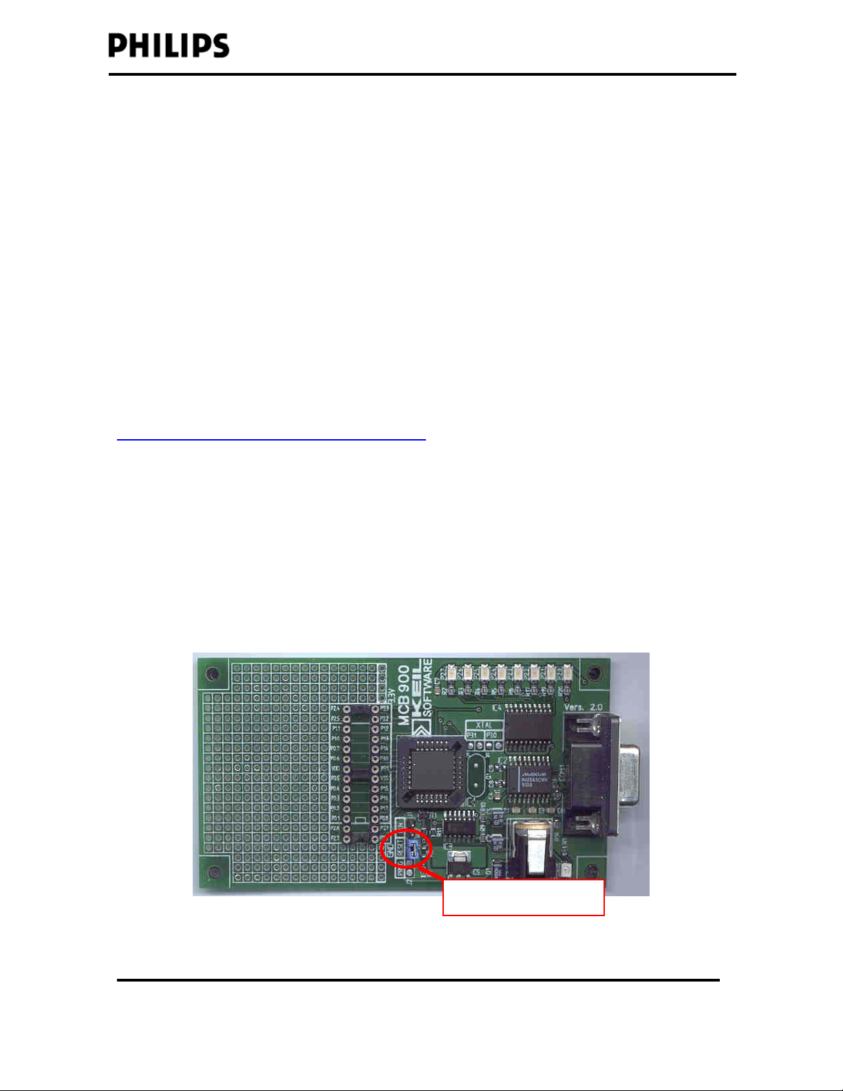
The PAB90x-1 board is designed as an add-on board to the MCB900 board from
Keil Software. (More information: http://www.keil.com/mcb900)
PAB90x-1 Programming functionality:
To program the 1K of on-chip Flash memory of LPC901/902/903 devices with
PAB90x-1, an MCB900 board from Keil Software is necessary. Before any devices
can be programmed, the P89LPC932 on the Keil MCB900 board needs to be
programmed with the ISP-to-ICP bridge code using the ISP software FlashMagic
(included on the CD). FlashMagic then also supports the programming of LPC90x
devices, however only in combination with the ISP-to-ICP bridge code on the
MCB900 as noted above. See sections 2 and 3 for details.
PAB90x-1 Evaluation Board functionality:
After the user code has been programmed using PAB90x-1 + MCB900 as
described above, PAB90x-1 can be used as a small stand-alone board to evaluate
the user software. The following elements are available for evaluation:
• LED:
PAB90x-1 provides one low-active green LED (D1) that can be hooked up to
any port pin of the LPC90x using the LED header pin.
• Potentiometer:
PAB90x-1 provides a potentiometer, which delivers 0V to 3.3V to the V_AN
(“analog voltage”) header pin.
PAB90x-1 Getting Started V1.0 Page 3

• Push Button:
A push button (PB) is provided as an external trigger in an application or to
wake up the LPC90x from Power-Down mode.
• Crystal Oscillator socket
Different Crystal oscillator values can be tested in socket Y1.
A 12 MHz crystal is provided.
• Access to LPC90x port pins:
The header rows J3 and J4 provide access to the 8 port pins of the LPC90x.
For details see section 5, ”Evaluating the LPC90x using PAB90x-1”
PAB90x-1 Getting Started V1.0 Page 4

2. PAB90x-1 Programming Board Setup
Introduction
The LPC90x devices are programmed using a programming method called “ICP”
(In-Circuit Programming). In contrast to some of the larger LPC900 family
members, the LPC90x devices do not offer other programming methods like
Parallel Programming, In-System Programming (ISP) or complete In-Application
Programming (IAP). Details on the ICP specification can be found on the included
CD (folder “ICP Programming Specification”)
FlashMagic is the preferred software used to perform ISP on the Philips Flash
Microcontrollers that support this programming method. To provide the same
programming Interface but still do the ICP programming method that the LPC90x
devices require, Philips Semiconductors developed ISP-to-ICP bridge software
that can translate between ISP and ICP. In other words, if this ISP-to-ICP bridge
code is downloaded to a microcontroller (e.g. LPC932), FlashMagic can be used to
program the LPC90x devices (see figure below).
The ISP-ICP bridge application
PAB90x-1 Getting Started V1.0 Page 5

As already mentioned in the overview, the PAB90x-1 programming board is
designed as an add-on board to the MCB900 board from Keil Software. Before any
P89LPC90x devices can be programmed, the LPC932 microcontroller on the Keil
MCB900 board needs to be programmed with the ISP-ICP bridge code using the
ISP software FlashMagic (included on the CD). FlashMagic then also supports the
programming of P89LPC90x devices, however only in combination with the
ISP-ICP bridge code on the MCB900 as noted above.
Step 1) Install FlashMagic from the included CD
Go to folder “FlashMagic” on the included CD ROM and execute “FlashMagic.exe”.
Follow the instructions to install FlashMagic.
(The latest version of FlashMagic can always be found at
www.esacademy.com/software/flashmagic)
Step 2) Program the LPC932 device on the MCB900 board with the ISP-ICP
bridge code using the FlashMagic software you installed in step 1
The ISP-ICP bridge code is included on the CD (folder “ISP ICP bridge source
code”).
• Set the jumper on the MCB900 board to the RESET position:
Reset mode LPC932
PAB90x-1 Getting Started V1.0 Page 6

• Connect the MCB900 to your PC COM port using a serial cable.
• Power up the MCB900 board.
• Start FlashMagic (Start | Programs | FlashMagic | FlashMagic)
• Go to “Options | Advanced Options | Hardware Config” and make sure
the box “Use DTR and RTS to enter ISP mode” is clicked:
• Go to “Options | Advanced Options | Security” and make sure the
“Protect ISP code” option is selected:
• Select the COM port you will be using to program the LPC932.
• Select the P89LPC932 as the device to be programmed
• Select baud rate 9600
• Browse to the prog90x.hex file that is on the CD in the “ISP ICP bridge
source code” folder
PAB90x-1 Getting Started V1.0 Page 7
• Check the “erase all” Flash box.

• Click start program the ISP-ICP bridge code into the P89LPC932:
PAB90x-1 Getting Started V1.0 Page 8

Step 3) Attach the PAB90x-1 board to the MCB900 board
• Disconnect the power cable from the MCB900 board
• Set the jumper on the MCB900 board from “Reset” to “RUN”
• Plug the PAB90x-1 programming board onto the MCB900. Make sure all
28 pins align correctly. Be aware of the locations for pin position 1 for
when you insert a device later on (see image below).
PIN 1
Set Jumpers to ICP
RUN mode for LPC932
NOTE: If you have an MCB900 board without a 28-pin DIP socket, please use the
included 28-pin DIP socket and solder it into the MCB900 board.
NOTE: There are 3 jumpers on the PAB90x-1 board, these have to be all set to the
position “ICP_xxx” closest to the edge of the board in order for the LPC90x to enter
ICP mode.
Your MCB900 / PAB90x-1 programming hardware is now set up.
To program a device, continue with the following section.
PAB90x-1 Getting Started V1.0 Page 9

3. Programming the LPC90x using PAB90x-1
Once all setups from the previous chapter have been made, using FlashMagic the
LPC90x devices can be programmed in 5 steps corresponding to the numbered
steps on the FlashMagic User Interface.
Step 0.
• Disconnect the power cable from the MCB900 board
• Insert an LPC90x device in EITHER the SO8 socket OR the DIP8 socket of
the PAB90x-1 board. Make sure PIN 1 is aligned correctly.
• Make sure all jumpers are set to “ICP_….”.
• Disconnect any cables from J3 and J4 as connected hardware might
interfere with the programming signals.
• Plug the power cable back in to enter ICP mode on the LPC90x (the ICP
mode is only entered on power-up of the MCB900). LED P2.3 on the
MCB900 board should light up.
• Start FlashMagic (Start | Programs | FlashMagic | FlashMagic).
Step 1.
• Select the COM port (make sure it is not already taken by another
application, e.g. some PDA software)
• Select a baud rate of 19200 baud (the ISP-ICP bridge application has a
fixed baud rate of 19200 baud)
• Select the LPC90x device you would like to program (the PAB90x-1 board
can program LPC901, LPC902, and LPC903. (For programming of LPC906
/ LPC907 / LPC908, you need the PAB90x-2 board due to the differences in
pinout.)
PAB90x-1 Getting Started V1.0 Page 10

• At this point you can do a quick read of the device signature bytes to make
sure you’re connected to the LPC90x:
If FlashMagic cannot read the Device Signature or you get all FF’s, please
check your setup. The correct signature bytes are:
LPC901: 15h DDh 0Dh; LPC902: 15h DDh 0Fh; LPC903: 15h DDh 10h
Step 2.
Select which Flash blocks should be erased before the programming operation.
Step 3.
Select the hex file to be programmed.
Step 4.
Can be used to set security bits and fill unused Flash (optional)
Step 5.
Start programming!
“Hello World” Example
Provided on the CD provided is some example code for the LPC903, which uses
the UART to send out the string “Hello World : )”. (Only the LPC903 has a UART.)
The example code can be programmed using the 5 steps described above.
To run the user code after you programmed it, please refer to section 4.
PAB90x-1 Getting Started V1.0 Page 11

4. Running User code on the LPC90x using PAB90x-1
When a device has been successfully programmed, use the following steps to run
the programmed code:
Step1: Disconnect the power cable from the MCB900 board
Step 2: Put the 3 jumpers on the PAB90x-1 board to RUN mode
Step 3: Reconnect power – your user code is now running.
Jumpers to RUN mode
To see the UART sending the string from the “Hello World” example you can open
a terminal program, e.g. HyperTerminal:
- To have access to the COM port of the PC, start the program
'HyperTerminal'. (START | PROGRAMS | ACCESSORIES |
COMMUNICATIONS | HYPERTERMINAL)
- Click on 'Properties' and check the following settings: 9600 baud, 8 data bits,
1 stop bit and no flow control.
- The P89LPC903 will send "Hello World : )" through the UART with 1 sec
delays, which is displayed on the screen.
PAB90x-1 Getting Started V1.0 Page 12

PAB90x-1 Getting Started V1.0 Page 13

PAB90x-1 Getting Started V1.0 Page 14

Other functions can be found in the ISP menu:
PAB90x-1 Getting Started V1.0 Page 15

5. Evaluating the P89LPC90x using PAB90x-1
As described in section 4, the user code that has been programmed using
PAB90x-1 + MCB900 can be run and PAB90x-1 can now be used as a small
stand-alone board to evaluate the user software. The following elements are
available for evaluation:
• LED:
PAB90x-1 provides one low-active green LED (D1) that can be hooked up to
any port pin of the LPC90x. A LOW level at the LED header pin turns the
LED on, a HIGH level turns it off.
• Potentiometer:
PAB90x-1 provides a potentiometer, which delivers 0V to 3.3V to the V_AN
(“analog voltage”) header pin. This analog voltage can directly be fed to the
on-chip comparator on the LCP90x or the header pins V_C and
RC_CHARGE can be used to do a slope conversion Analog-to-Digital
Converter (together with resistor R2 and capacitor C4). This slope
conversion ADC is described in detail in Application Note AN10187,
“Low-cost A/D-Conversion with Philips LPC Microcontrollers”. This
Application Note (among others) is included on the CD.
• Push Button:
A push button (PB) is provided as an external trigger in an application or to
wake up the LPC90x from Power-Down mode using the keyboard interrupt
feature. If header pin KBI is hooked up to a port pin in quasi-bidirectional
mode (providing an internal pull-up resistor), the level at the port pin will be
HIGH if the button is not pressed. It will go LOW when the button is pressed.
Please note that the button might “bounce”, so you might get several
transitions at the port pin.
PAB90x-1 Getting Started V1.0 Page 16

• Crystal Oscillator socket
Different Crystal oscillator values can be tested for the LPC901 in socket Y1.
To use an external crystal, FlashMagic offers you to reprogram UCFG1, the
User-Configuration Register of the LPC90x devices
(ISP | Device Configuration):
Please note: Only LPC901 features external crystal pin inputs. LPC902 and
LPC903 can only be run from the internal RC oscillator or the internal
Watchdog oscillator.
Please note: The capacitors C2 and C3 are the capacitors belonging to the
crystal oscillator circuit. These capacitors are just recommendations. Since
many factors play a role in oscillator circuits (board design, board layout,
tolerances of components etc.), it is HIGHLY RECOMMENDED to do
extensive testing of the oscillator circuit in your own hardware to make sure
your oscillator circuitry works reliably under different conditions like
temperature and voltage.
• Access to LPC90x port pins:
The header rows J3 and J4 provide access to the 8 port pins of the LPC90x
(see next page).
PAB90x-1 Getting Started V1.0 Page 17

PAB90x-1 Getting Started V1.0 Page 18

Using the LED, the Potentiometer and the Push-Button in a pre-programmed
example
There is an example program preprogrammed into the device sample that came
with your PAB90x-1 board. The source code is included on the CD, in folder
“LPC901_2_3 LED blinker and SD ADC”.
The software blinks the LED with a frequency that depends on the position of the
potentiometer. While the push button is pressed, the device is held in Reset.
To run the software, do the following:
(please also see “1_minute_demo_setup.pdf” on the included CD):
• If you already erased the sample that came with the PAB90x-1 board:
Program the “D:\LPC901_2_3 LED blinker and SD ADC\blinky2.hex” file
into the LPC90x as described in section 3.
• Connect the KBI, LED, RC_CHARGE, V_C and V_AN header pins to the
LPC90x as described in the image below:
PAB90x-1 Getting Started V1.0 Page 19

• Make sure all three jumpers are set to “RUN” (left position)
• Attach the provided battery pack to J6 (red cable = “+”) an turn it ON
• The LPC90x demo runs.
o The LED will blink according to analog voltage selected with
potentiometer (turn potentiometer to adjust frequency)
o Push Button will reset the application
The Demo code makes use of the on-chip analog comparator on the LPC90x.
Together with resistor R2 and capacitor C4, the software uses the on-chip analog
comparator as a Sigma-Delta Analog to Digital Converter. This method is
described in detail in AN10187, “Low-cost A/D-Conversion with Philips LPC
Microcontrollers”. This Application Note (among others) is included on the CD.
The digital representation of the analog voltage provided by the potentiometer
controls the frequency with which the LED is turned on and off.
While the push button is pressed, it holds the application in Reset via a LOW signal
on the Reset pin. Please note that the LPC90x is equipped with an on-chip
Power-On Reset (POR) circuit that automatically provides a clean reset signal to
the device on power-up. The external Reset pin is ONLY needed if the chip needs
to be reset manually or by another device in the application. Most of the time, the
internal power-on reset is sufficient and this pin (P1.5) becomes a valuable
general-purpose input pin.
PAB90x-1 Getting Started V1.0 Page 20
Table of contents
Other Philips Motherboard manuals
Popular Motherboard manuals by other brands

DFI
DFI P2XBL DE+ user manual

Linear Technology
Linear Technology DC2007A-A Demo Manual

Fujitsu Siemens Computers
Fujitsu Siemens Computers D1387 Technical manual

SOYO
SOYO 82430 TX Users guide and technical reference

VIA Technologies
VIA Technologies EPIA N-Series operating guide

Texas Instruments
Texas Instruments ADS1672EVM user guide