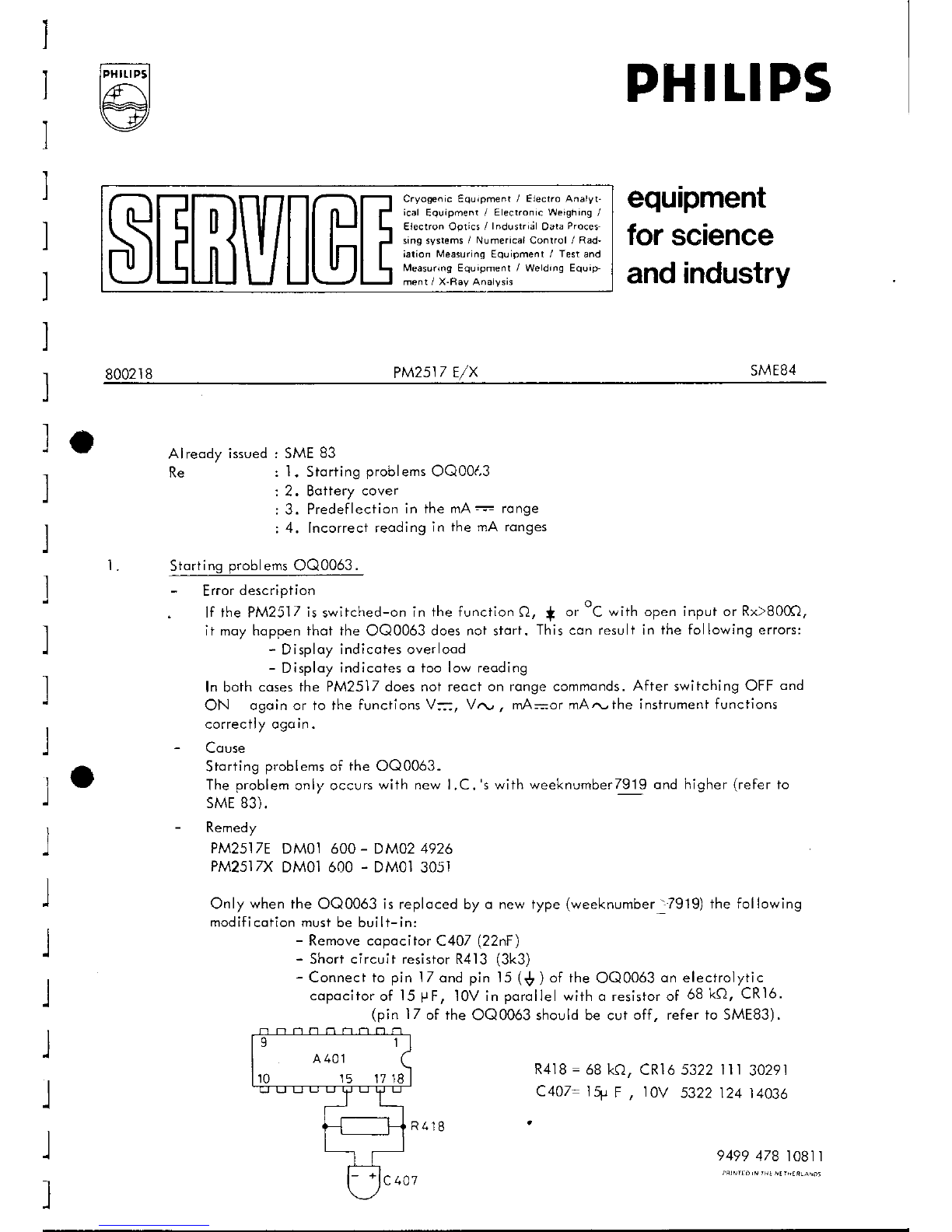
PHITIPS
equipment
forscience
andindustry
SMEB4
$EHUIGE****m
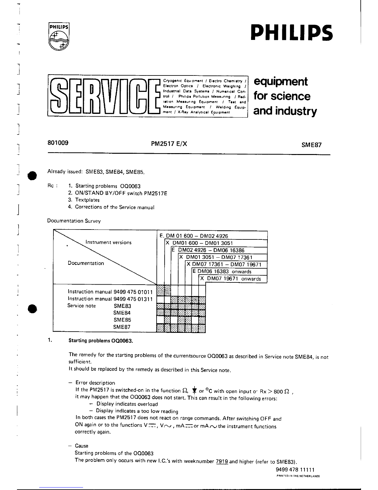
800218 PM2s17
E/X
le
l
l
L
Alreody issuedr SME
83
Re : 1. Storiing
problems
OQ00l,3
: 2. Botiery
cover
: 3. Predeflecfion
in the mA
=':=
ronge
: 4. lncorrectreoding
in the mA ronges
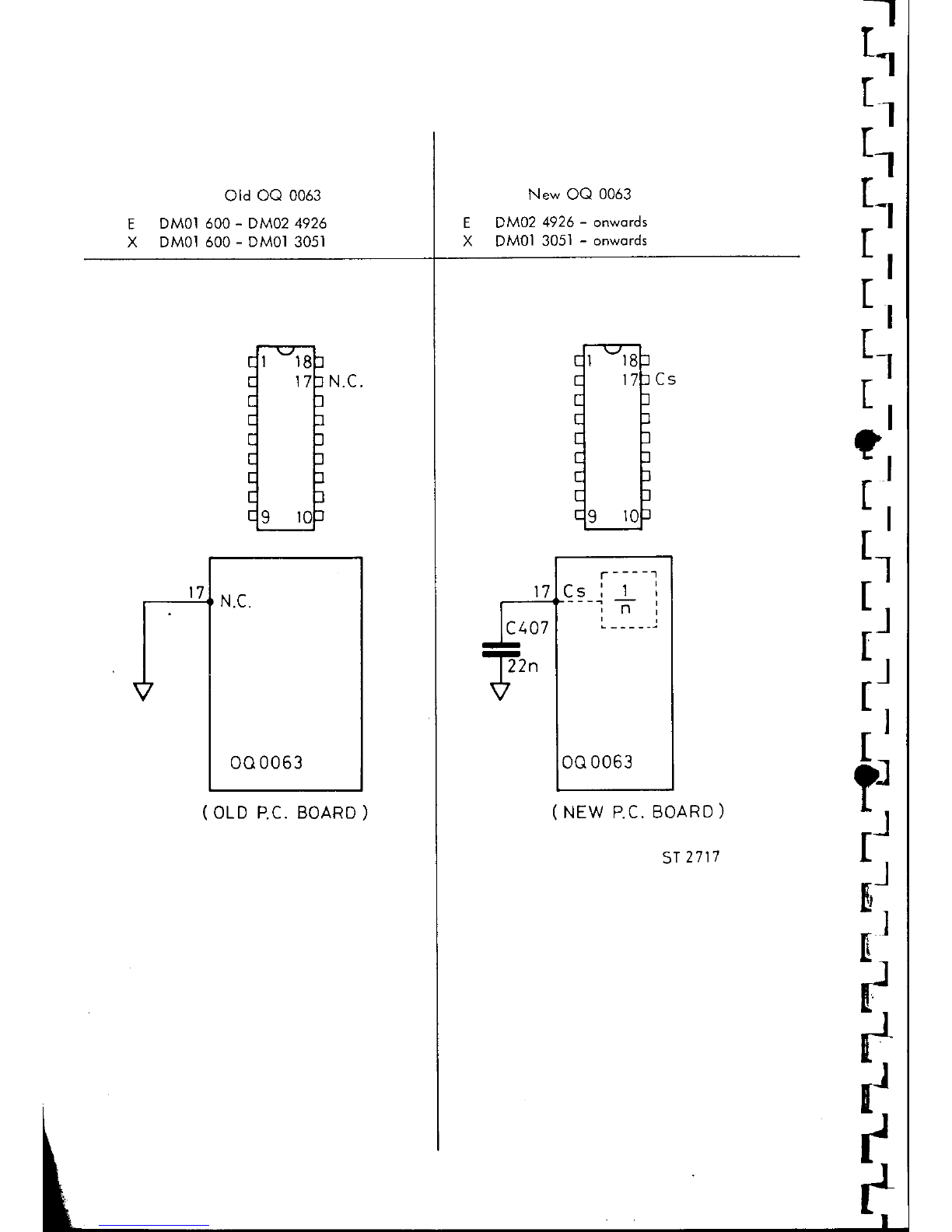
Storting
problems
OQ0063
.
- Error
description
. lf the PM251/ isswitched-on
in the function
Q, d or oC *ith op.n input or Rx 8000,
it moyhoppenthot the OQ0063 doesnot storf. Thiscon resultin the following errors:
- Disploy indicotesoverlood
- Disploy indicoteso too low reoding
In both cosesfhe PM251Zdoesnot reoct
on rongecommonds.
After switching
OFF ond
ON ogoinor to the functions
V=, Vn , mA==ormArw the instrumentfunctions
correctlyogcr
in.
- Couse
Storting
problems
of the OQ0063.
The
problem
only occurs
with new LC. 's
with weeknumberT9l9ond higher (refer
to
sME83).
- Remedy
PM25I7E
DMOI600
- DM024926
PM2stTX
DM01600
- DM0l
3051
Only
when
theOQ0063isreploced
by
o newtype
(weeknumber
'-79.19)
thefollowing
modificotionmust
bebuilt-in:
- Removecopocitor
C407
(22nF
\
- ShortcircuitresistorR4l3 (3k3)
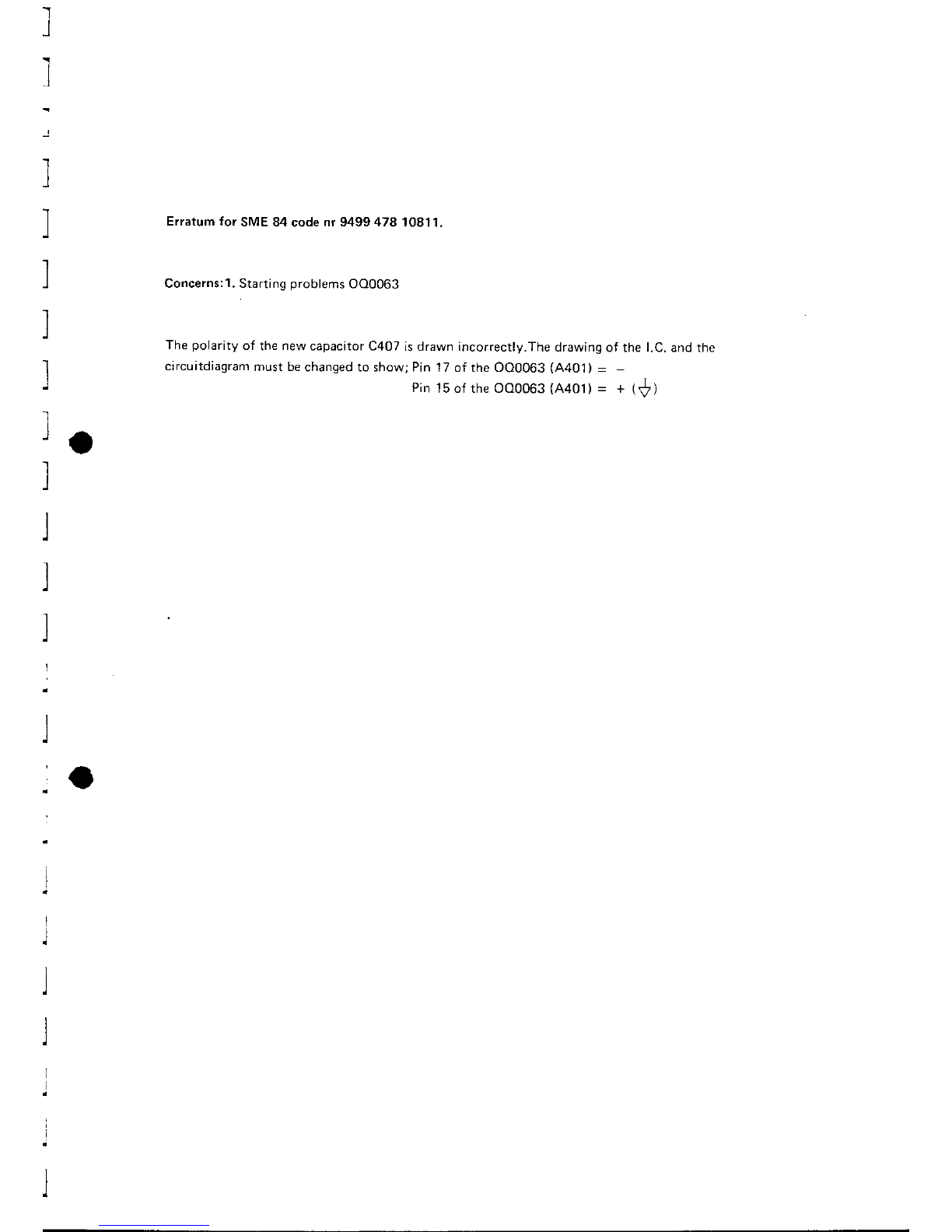
- Connectto
pinlZ ondpinl5 ($ )
ofthe
OQ0063
onelectrolytic
copocitor
of l5 PF, 10Vin
porollel
witho resistorof 68
kQ,CR16.
(pin lZ of the
OQ0063shouldbecut
off, referto SME83).
R4l8
=68kO,
CRl65322
ll r 30291
c407- 1+ F , 10V s322124
t4036
949947810811
10 15 1718