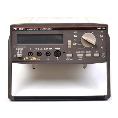
Philips pm2521 User manual

ytt4cj. . o*4r^,
(3
Automatic
Multimeter
PM2521
Operating
Manual/Gebrauchsanleitung/Notice
d'Emploi
9499470 17901
820329t02t. .
PHITIPS

AutomaticMultimeter
PM2521
Operating
Manual/Gebrauchsanleitung/Notice
d'Emploi
9499470 17901
820329to2t.
t
I
I
I
I
I
I
I
lr
I
T
I
I
I
I
lo
t
I
I
I
I
I
I
IPHI[IPS

IMPORTANT
Incorrespondence
concerning
thisinstrument,
please
quote
thetypenumber
and
serial
number
as
given
on
thetype
plate.
NOTE: Thedesign
of thisinstrument issubjectto continuous development
and improvement.
Consequently,
thisinstrument may incorporateminor changes
in detail from the information
containedin thismanual.
SAFETY INSTRUCTIONS.Thisequipmenthad been
built and testedaccordingto saÍetyspecificationsfor
electronic
measuring
equipmentlaid down by DIN 57411 part 1
/2.8O,
VDE O411 Part 112.80,IEC 348-ll,
and hasleft the factory in perfect
condition from a
saÍety
point of view. In orderto maintain
this condition
andto ensurethe safe
operation,the usermust follow the instructions
and warning
notices
containedin the
directionsfor use.
Priorto useafterstorageand transport,the equipment
should
first beexaminedfor any
mechanical
Íaults. lf thereisany doubt that the safety measures
are
no longer
adequate,their effectiveness
shouldbechecked.lf its
safetycanno longer
be
quaranteed,
the equipment
shouldbetakenout of service
andsafeguardedagainstfurther use.Before
opening,
the equipment
shouldbedisconnectedfrom all electrical
sources.Service
and repair
work should
only becarried
out by experienced
qualifiedpersonnel
and by
following the standardsafety
procedure.
This equipment
belongsto safetyclass|| @ . Only the approveo
fuses
must beused.
The use
of repairedfuses
and the shorting
of the Íuse
holderisnot permitted.
WICHTIG
Bei
Schriftwechseltiber
diesesGeràt
wird gebeten,
die
genaue
Typenbezeichnung
und dieGeràtenummer
anzugeben.
Diesebefinden
sich
aufdem Leistungsschild.
BEMERKUNG: Die Konstruktion und Schaltung dieses Geràts wird stándig weiterentwickelt und verbessert.
Deswegen kann dieses Gerát von den in dieser Anleitung stehenden Angaben abweichen.
SfCHERHEITSHINWEISE.
Dieses
Gerát
ist
gemàss
DIN 57411Ieil 1/2.8O,
VDE 0411Teit 1/2.6O,tEC348-tt.
Schutzmassnahmenfi-tr
elektronische
Messgeràte,
gebaut
und geprirÍt
und hat das
Werk insicherheitstechnisch
einwandfreiemZustand
verlassen.
Um diesemZustand
zu erhaltenund einen
gefahrlosen
Betrieb
sicherzu
stellen;muss
derAnwender
dieHinweise
undWarnmerke
beachten,diein dieser
Gebrauchsanleitung
enthalten
sind.Vor der lnbetriebnahme
nachLagerungund Transportist
daraufzu achten,dassdasGeràtkeineme-
chanischen
Schàdenaufweist.Besteht
der Verdacht,
dassdie Schutzmassnahmen
nicht mehr ausreichend
wirksam
sind,istderen
Wirksamkeit
zu pr[.ifen.
lstder
Schutznichtmehr
sichergestellt,
soistdasGerát
ausser
Betriebzu nehmenund
gegen
Inbetriebnahme
zu
sichern.DasGerát
istvor
demÓffnenvon
allenSpannungs-
quellen
zu trennen.Wartungs-
und Uberholungsarbeiten
di.rrfennur unter Beachtung
dergebotenen
Vorsichts-
massnahmen
durch eingearbeiteteFachleute
ausgefiihrt
werden.Dieses
Geràtist
ein Gerát
derSchutzklasseIl, @.
Es
dilrfen nur die vorgeschriebenen
Sicherungen
verwendet
werden.Die Verwendungreparierter
Sicherungen
unddasKurzschliessen
des
Sicherungshalters
sindnichtzulàssiq.
IMPORTANT
RECHANGE
DESPIECES
DETACHEES
(Béparation)
Dansvotre
correspondance
etdansvos
réclamations
se
rapportant
àcetappareil,veuillez
TOUJOURS
indiquer
lenumérode
typeetlenuméro
de
série
quisont
marqués
sur
la
plaquette
decaractéristiques.
REMAROUES. Cet appareil estI'objet de développements et améliorations continuels. En conséquence, certains
détails mineurs peuvent différer des informations données dans la présente notice d'emploi et
d'entretien.
REGLES
DE SECURITE.
Cetappareil
aétéconstruit
ettesté
suivant
les
normes
DIN 57411,
premièrepartie
12.8O,
VDE 0411,
premièrepartie
/2.80,
IEC348-llmesures
de
protection
pour
appareilsélectroniques
demesure,et il a
quitté l'usine
dans
un état impeccable
du point devuede latechnique
desécurité.
Pour
rnaintenircetétatet
s'assurer
d'un Íunctionnement
sansdanger,l'utilisateur
doit prender
enconsidération
lesinstructions
et tes
avertissements
qui sont contenus
dansleprésent
moded'emploi. Avant sa
mise
enserviceà la
suiteoe
l'entreposage
et du transport,il convientde veiller
àce
que l'appareil
ne
présente
aucunendommagement
mécanique.
Si l'on soupqonne
que les
rnesures
de protection ne
sontplus
suffisammentefficaces,il y à lieu
devériÍierleurefficacité.
Au cas
oÈ laprotection n'est
plus
assurée,l'appareil
doit êtremis horsservice
et
desdispositions
doiventêtre
prisespour garantir
qu'il ne
sera
pas
utilisé.
Avant d'êtreouvert,l'appareil
doit
êtreisolé
de toute sourcede tension.Les
travaux
d'entretien
et de remise
enétat nedoivent êtreexécutés
qu'en respectantles
mesures
de précaution
proposées
parun personnel
compétent.
Cetappareil
estun appareil
de
la
classe
de
protection
ll, El .Seuts,
les
fusibles
prescritspeuvent
êtreutilisés.L'utilisation
defusibles
réparés
et lecourtcircuitage
du porte-fusibles
sont interdits.
O N.v.
pHILtps'cLoErLAMpENFABRTEKEN
-
EtNDHovEN
-
THENETHERLANDS-1982
PRINT€OIN THE
NEÍHERLANDS

CONTENTS
1. INTRODUCTION
2. TECHNICAL
DATA
2.1.
2.1.1.
2.1.2.
2.1.3.
2.1.4.
2.1.5.
2.1.6.
2.1.7.
2.1.8.
2.1.9.
2.1.10.
2.1
.11
.
2.2.
2.2.1.
2.2.2.
2.2.3.
2.2.3.1.
2.2.3.2.
2.2.4.
2.2.4.1.
2.2.4.2.
2.2.4.3.
2.2.5.
2.2.6.
2.2.7.
2.2.8.
2.2.9.
3. ACCESSORTES
?1
5.2. 3.2.1.
3.2.2.
3.2.2.1.
3.2.2.2.
3.2.2.3.
3.2.2.4.
3.2.2.5.
3.2.2.6.
Page
Measuring
performance
Directvoltagemeasurements. ...14
Alternatingvoltagemeasurements ... 15
Directcurrentmeasurements
Alternatingcurrent
measurements
dB measurements
Resistancemeasurements
Diode
measurements
Temperaturemeasurements
Frequency
measurements
Timemeasurements
ïrigger level
Generaldata
Conversioncharacteristics
(ADC) .
Visual
representation
of thedisplav
Operationconditions
Climatic
conditions
Mechanical
conditions
Mainssupply
conditions
Mains
supply
voltage
Mainssupply
frequency
Powerconsumption
Inputterminalsarrangement
. . . .
Timefunction
(ADC)
Calibration
lVlechanical ........25
Safety .......25
Accessories
suppliedwith
the
PM2521
Optionalavailableaccessories ........26
Summary ......26
Specifications
of the optionalaccessories . . . 26
HighTension(HT)
probePM9246 ......26
ShuntPM9244andCurrenttransformerPM9245 ....... 26
DataHoldprobePM9263.... .......27
Pt-1OOtemperatureprobePM924g... .......27
HighfrequencyprobePM92l0andaccessorysetPM92i2
... .... 28
DimensionsoÍ 19 inchrackmountinq
set. . . . . 28
IJ
14
14
to
1l
18
19
zv
20
21
22
23
24
24
24
24
24
24
25
25
25
25
25
25
25
zo
26

4. PRINCIPLE
OF
OPERATION Page
29
4.1.
4.1.1.
4.1.2.
4.1.3.
4.1.4.
4
.1.5.
4.1.6.
4.1
.7.
4.2.
4.3.
5. INSTALLATION
5.1.
5.1
.1.
5.1.2.
5.1.3.
5.1.4.
6. OPERATION
o.t.
Analogsection
Measuringvoltages,currents,
resistances
anddiodes
Measuringtime and
Írequency
Measuringtemperatures
dB measurements
Measurements
in relative
referencemode .
Control
of theanalog
section
ADC
Control
section
Displaysection
31
Mainssupply ....31
Safetyinstructions ...31
Replacingthemainsfuse .....31
Adaption
tothe
mains
voltage . . . . 31
Adaption
tothemainsfrequency . . . . 31
29
29
29
29
29
29
29
29
30
30
32
Switching-on .....32
6.2. Controls .......32
6.2.1. Frontpanel ....32
6.2.2.
Rearpanel .......34
6.3. Zerosetting ....34
6.4. Measuring .......35
6.4.1. Standardmeasurements ....35
6.4.1
.1.
Directvoltagemeasurements(V---
) .... .......35
6.4.1.2. Alternatingvoltage
measurements
(V- rms) . . . . . . 36
6.4.1.3.Decibel
measurements(dB) .....37
6.4.1
.4.
Directcurrentmeasurements(A:) ....... 38
6.4.i.5. Alternatingcurrentmeasurements
(A
- rms) . . . . 39
6.4.1.6.Resistancemeasurements(Sl)
. ...40
6.4.1.7.
Diodemeasurements(+f-) .....41
6.4.'l
.8.
Temperaturemeasurements(oC)
. ......42
6.4.1.9.
Frequencymeasurements
(Hz) . . . 43
6.4.1.10.Time
measurements
(s) .. . . 45
6.4.1.l1.Peakvoltagemeasurements. ....48
6.4.2. Extendedcapabilities(optional) ...... 50
6.4.2.1.
Hightensionmeasurements .......50
6.4.2.2.Highcurrentmeasurements
(A: and
A- rms) . . . 51
6.4.2.3.
DataHoldmeasurements ....52
6.4.2.4.Highfrequencymeasurements. .....53

LIST
OF
FIGURES Page
126
Fis.
1.
Fis.2.
Fig.3.
Fis.4.
Fis. 5.
Fis.6.
Fis. I
.
Fis. 8.
Fis. 9.
Fis.
10.
Fig.
11.
Fig.12.
Fis.
13.
Fis.
14.
Fis.15.
r
rg.tb.
Fig,17
.
Fig.
18.
Fis.
19.
Fig.
20.
Fis.21
.
Fig.22.
Fig.23.
Fí9.24.
Fis.25.
Fig.26.
Fig.27
.
Fis.
28.
Accessories
supplied
with the PM2521
HT
probe
PM9246 126
ShuntPM9244.... 126
Current
transformer
PM9245 126
DataHoldprobePM9263.... 126
Pt-100
temperature
probe
PM9249 . . . 126
HF
probe
PM9210 130
AccessorvsetPM9212.... 130
Dimensionsfor 19 inchrack
Basicbuilt-up oÍ PM2521 .
Block diagramoÍ PM2521 134
Removing
thetop cover 138
Adaptingthe mains
transformer 138
dB measurements 37
Temperature
probe
connection . 42
Triggerlevelselection
in function Hz . . . 44
Normalmodetriggerlevel
selectionin functions 45
Special
modetriggerlevelselectionin functions . 45
Dataholdconnection 47
Triggerlevelselectionin peak
voltagemeasurement
mode 49
Peakvoltagemeasurements
. 49
Front panel 142
Rear
panel 142
Measuring
set-up
for HT probe
PM9246 146
Measuringset-up
for shunt
PM9244
mountrng
set 130
134
Measuringset'up
for current
transformerPM9245
Measuringset-up
for data
holdprobe
PM9263
Measuringset-up
for highfrequency
probe
PM9210
146
150
150
150

INHALT
1. EINLEITUNG
2. TECHNISCHE
DATEN
2.1.
2.1.1.
2.1.2.
2.1.3.
2.1.4.
2.1.5.
2.1.6.
2.1.7
.
2.1.8.
2.1.9.
2.1.10.
2.1.11.
2.2.
2.2.1.
2.2.2.
2.2.3.
2.2.3.1.
2.2.3.2.
2.2.4.
2.2.4.1.
2.2.4.2.
2.2.4.3.
2.2.5.
2.2.6.
2.2.7.
2.2.8.
2.2.9.
3. ZUBEHOREN
Seite
Messleistung ......56
Gleichspannungsmessungen .......56
Wechsefspannungsmessungen .....57
Gleichstrommessungen ......58
Wechselstrommessungen ...59
dBMessungen .......60
Widerstandsmessungen ......61
Diodenmessungen
. .......62
Temperaturmessungen .......62
Frequenzmessungen ...63
Zeitmessungen .......64
Triggerpegel ...65
AllgemeineDaten. ......66
Analog-DigitalUmsetzung(ADC) ...66
Sichtanzeige .......66
Betriebsbedingungen ......66
KlimatischeBedingungen .....66
MechanischeBedingungen .......66
BetriebsbedingungSpeisungnachlEC359 . . . 67
Netzspannung.... .......67
Netzfrequenz ......67
Leistungsaufnahme. ...67
AnordnungderEingangsklemmen ...67
Zeitfunktion(ADC) ......67
Kalibrierung ...67
MechanischeDaten. ......67
Schutz ....67
68
55
cb
3.1.
3.2.
3.2.1.
3.2.2.
3.2.2.1.
3.2.2.2.
3.2.2.3.
3.2.2.4.
3.2.2.5.
3.2.2.6.
ZubehórenimLieferumfangdesPM2S2l
enthalten ....... 68
WahlweiseerhàltlichesZubehór ....68
ZusammenÍassung. ...68
SpezifikationesdesWahlzubehórs .....68
Hochspannungs-MesskopfPMg246 ....68
Shunt
PM9244
und
Stromwandler
PM9245
. . . .
Messkopf
PM9263
mit"Data-hold"
. .
Pt-l0OTemperaturmeszÍr,ihlerPMg24g ...... 69
HF-TastkopfPM9210
undZubehórsatzPM9212 . . . 70
AbmessungenÍtir19inchGestelleinbau ......70
68
AO

4. FUNKTIONSPRINZIP
Seite
71
4.1.
4.1.1.
4.1.2.
4.1.3.
4.1.4.
4.1.5.
4.1.6.
4.1.7
.
4.2.
4.3.
Analogteil .....71
MessungvonSpannung,
Strom,Widerstandund Dioden . . . . . . 71
MessungvonZeitundFrequenz
. .......71
MessungvonTemperaturen ....... 71
dB-Messungen ...71
Messungin relativer
Referenz
Betriebsart . . . 71
SteuerungdesAnalogteils.... .......71
Anafog-DigitalUmsetzer(ADc)
. .....71
Steuerteil ....72
Anzeigeteil ...72
NetzspannunS.... ......73
Sicherheitsvorkehrungen .....73
ErsetzenderNetzsicherung. ....73
AnpassungandieNetzspannung .......73
AnpassungandieNetzfrequenz ......73
5. INBETRIEBNAHME
5.1
.c.t.t.
c- t-2.
5.1
.3.
5
.1
.4.
BETRIEB
6.1.
6.2.6.2.1.
6.2.2.
6.3.
73
6. 74
Einschalten .....74
Bedienungselemente ...-.74
Frontplatte ......74
Rr-ickwand ......76
Nullsetzen ...76
6.4. Messen .....77
6.4.1
. Standardmessungen .......77
6.4.1
.1.
Gleichspannungsmessungen(V-.
) .... .......77
6.4.1
.2.
Wechselspannungsmessungen(V-
rms) .....78
6.4.1.3.dB-Messungen(dB)
. ......79
6.4.1.4.
Gleichstrommessungen(A=
) .....80
6.4.1.5.Wechselstrommessungen(A-
rmsl ....81
6.4.l.6.Widerstandsmessungen ......82
6.4.1
.7.
Diodenmessungen(}).... ....83
6.4.l.S.Temperaturmessungen(oC) ...84
6.4.1.9.Frequenzmessungen(Hz)
.. .......85
6.4.1
.l0.Zeitmessungen(s). ..... 87
6.4.1
.ll.Spitzenspannungsmessungen
. ...90
6.4.2. ErweiterteMóglichkeiten(wahlweise)
.... ...92
6.4.2.l.MessungvonHochspannungen .....92
6.4.2.2.MessunghoherStróme(A-
undA- rms) ....... 93
6.4.2.3.
Messungenmit"Datahold". ......94
6.4.2.4.
Hochfrequenzmessungen ....95

BILDVERZEICHNIS Seite
Mit dem
PM2521
gelieÍerte
Zubehóren . . . . 126
HochspannungsMesskopfPMg246 ......126
ShuntPM9244.... ....126
StromwandlerPM924S ....126
MeszkopfPM9263mit"DataHold". ....126
Pt-l00TemperaturftihlerPM924g.... ...126
HFTastkopf
PM9210 ....130
ZubehórsatzPMg2l2 .....130
Abmessungftir19inchGestelleinbau ......130
GrundaufbaudesPM2S2l ......134
BlockschaltbilddesPM2Szl
... ....134
AbnehmenderAbdeckel.... ...138
AnpassendesNetztransÍormators ...138
dB-Messungen ...... 79
TemperaturÍr-ihlerAnscnruss 84
TriggerpegelwahlinFunktionHz ...... 86
Normale
Betriebsart
ftir
Triggerpegelwahl
in
Funktion
s. 87
SpezielleBetriebsartftir
Triggerpegelwahl
inFunktion
s
. 87
DataHoldAnschluss ...... 89
Triggerpegelwahl
bei
Messung
von
Spitzenspannungen 91
Messung
vonSpitzenspannungen 91
Frontplatte .. i42
Rtickwand . . 142
MessanordnungfurHochspannungsmesskopfPM9246.... ...... 146
MessanordnungfrirShuntPM9244 .....146
MessanordnungfÍrStromwandlerPMg24s ..... 150
Messanordnungfr,irMesskopf
PM9263
mit"Data
Hold"
. . . 150
MessanordnungfrirHochfrequenzTastkopÍPM9210 ..... 150
Abb. 1.
Abb. 2.
Abb. 3.
Abb. 4.
Abb. 5.
Abb. 6.
Abb. 7.
Abb. 8.
Abb. 9.
Abb.10.
Abb.
11.
Abb.
12.
Abb.
13.
Abb.14.
Abb.15.
Abb.16.
Abb.17.
Abb.18.
Abb.
19.
Abb.20.
Abb.21.
Abb.22.
Abb.23.
Abb.24.
Abb.25.
Abb.26.
Abb.2t
.
Abb.28.

Operatingmanual

IJ
1. INTRODUCTION
ThePM 2521is
amicrocomputercontrolleddigital
multimeter.Thetypeof microcomputerusedisa3035
with a4k external
ROM.
Thanks
to the
microcomputer
extra
measuringfunctions
areincorporated,
in
addition
to the standardmultimeter
measuringfunctions.
Theseextra
measuring
functionsmake
it possible
to measure
thestandard
multimeter
measuring
signalsin other
units.
The standardmultimeter
Alternating
voltage
(V -
Directvoltage
(V -- )
Alternating
current
(A -
functions
of thePM
2521are:
The
extrameasuring
functions
of the
PM
Temperature
Pt100
(oC)
Frequency
(Hz)
Time
(s)
Direct
current (A
- )
Diodes( )f- )
Resistance
(0)
2521
are:
Trigger
level
(+/-)
Decibels
(dB)
Relative
reference
(zero
set)
rms)
rms)
A combination
of thetriggerlevelfunction arrd
thetime or frequency
function,make
selective
measurements
possi
ble.
The triggerlevelfunction itselÍ
alsoenables
peak
voltage
measurements.
The relative
referencefunction offers
the possibility
to select
apredetermined
relativereference
point.
Each
subsequentreading
will indicate
thepositive
andnegative
deviation
oÍ the relativereference
level.
Each
measuring
function is
subdividedinto anumber
of ranges.For range
switching
a
selection
canbemade
between
manual
or automatic
range
selection.
To get
anoptimum reading
in the ac
ranges
an
accoupledrms
convertor
isbuilt in the pM 2521.
The periodical
self-calibration
of thePM 2521ensures
high
accuracy
over
a longworking period.
The PM 2521 isequipped
with a
5 digitdisplay.
As display
a liquid
crystaldisplay
isused.lt gives
avery
clearreading,
especially
under
strong
light
conditions.
Ordering
number
for the instruction
stickeris
g4g94lO 16401

14
2. TECHNICAL
DATA
This
apparatus
hasbeen
designed
andtested
in accordance
with IEC
publication
348,Safety
Requirements
for ElectronicMeasuringApparatus,and
hasbeen
supplied
in asaÍe
condition.
The present
instruction
manual
containssome
informationand
warningswhich haveto be
Íollowedby theuserto ensure
safe
operationand
to retainthe apparatus
in asafecondition.
All valuesmentionedin this
description
are
nominal
;those
given
with tolerancesarebinding
and
guaranteed
by
the manufacturer.
Manufacturer
Type number
Designation
Measuring
quantities
2,1. MEASURINGPERFORMANCE
2.1.1. Directvoltagemeasurements
Ranges
NV
PhilipsMIGS
& |
PM2521
Digitalmultimeter
V :, V -, A -, A-, S), )f , s,Hz,
oC,
V pear
mV 200
2-20-200
2000v
Maximum input voltagein range2000 V 1000
V
Resolution 10
gV in range200mV
Number
of representationunits 21000
Accuracy 1 (0,03
% of reading
+ O,O1% of range)
Temperaturecoefficient ! O,O1
o/o
of reading
/oC
lnputimpedance Range Input impedance
200
mV
2V 20 MSt//60pF
20v 11
Mf,l//85
pF
200 v
2000 v 10
M0//95 pF
Offsetcurrentat input (20 pA
Series
ModeRejectionRatio (SMRR) 86 dB for ac
signals
at50 Hzt 1Yo
60 dB for acsignalsaï6O Hzt 1o/o
MaximumSeries
Mode
signal 2x rangeend
valuewith exceptionoÍ range2000 V
(1000
v)
Common ModeReiection
Ratio 100
dB f
or dc
signals
(CMRR) 100
dB
for acsignals
of 50 Hzor
60 Hz
1 1%
Maximum Common Modevoltage 400 V, 560 V peak
Responsetime 0.7s
without ranging
1,5s
includingranging
Zero
setting Automatic zero
setting
of the
ADC
Manual
with zero
ootentiometerat
thef
ront of the
PM 2521
Zeropoint drift 5gVloC between 0 oC and35 oC
20 1tV
loC between35 oC and 45 cC
Relative
reference
setting With pushbutton
ZERO SET atthe Íront oÍ the PM2521

15
Maximuminput
voltages
2.1
.2. Alternating
voltage
measurements
In
all
ranges:
BetweenHi and Lo
Between
Hi andearth
BetweenLo ar-rd
earth
Maximum
VHz product
1000V rms
1000
V rms
400V rms
107
R
anges
Maximuminput
voltage
in range2000V
Resolution
Numberof representation
units
Accuracy
(valid
between
3 %and100
%of range)
Temperatu
re
coefÍicienl
Input impedar-rce
CommonMode
RejectionRation
(cÍvlR
R
)
AC detector
Crestfactor
Response
time
Maximuminput
voltage
mV | 20O
v | 2 20 200 2000
600
v
10
pV
in
Measured
21000
range200 mV
valuelessthan
0,5"/o
oÍ rangeisdisplayed
as
zero
=
Í
f
o.o4 o.r 05 r ro 2o
+FREQUENCY N kHz 100
sr 3354
Range2000 V
40 Hz 60 Hz I t (O,3%of
reading
+ O,1ío/oof
range)
1 (0,03
%oÍ reading
/oC + 0,01% of range
loCi
Range Input impeciance
200mV
2V 20 ÍVlO//60
pF
20v 11 M52//85
pF
200 v
2000 v 10Í\aoil95
pF
100
dB for dc
signals
80dB
for acsignais50 Hz
or6OHz
! 1o/o
RMS
convertor,
accoupled
2 at rangeend
1,5
s
withoutranging
3 sincluding
ranging
Inallranges:
BetweenHi and Lo 600 V rms
BetweenHi andearth 1000
V rms
BetweenLo and
earth 400 V rms
Maximum dc voltage 400 V
MaximumVHz product rc7
Range
200 mV up to andincluding200 V
40 Hz
-
500 Hz I t (O,SZof
reading
+
0,15%ofrange)
dt 2OkHz I t (t %of reading
+O,15oÁ
ofrange)
at 100kHz I 1(5 %of reading
+ 1 %of range)
- '/.
OF REAONG
.'' -%OF RANGE

16
2.1
.3. Direct
current
measurements
R
anges
Maximum
input
currentin range
20A
Resolution
Number
of representation
units
Accuracy
Tem
peratu
re
coef
ficient
Voltagedrop over
shunt
1tA 2 20 200
mA 2 20 200
A220
104
1nA in range
2pA
2100
! (O,2
%of reading
+O,O5
o/o
of range)
! (O,O2
%of reading
/oC
+ 0,005
o/o
of range
loCl
Range Voltagedrop
2 pA
20 1tA
200 pA
2mA (2,5 mV
20
mA
200mA (25 mV
2A
204 (250 mV
Response
time 0,7s
without ranging
1,5
s
including
ranging
Protection Range 2 pA -
20mA;250 V rms
Range200 mA - 20 A are
not protected
lmax.
= 20 A Íor 20 seconds
Maximum Common Modevoltage 400 V rms,560 V pear
Maximuminputvoltages In
all
ranges:
BetweenHi and Lo 250 V rms
BetweenHi andearth 400 V rms
BetweenLo and earth400 V rms

't7
2.1
.4. Alternating
currentmeasurements
R
an
ges pA 2 20 200
mA 2 20 200
220
104
1
nA in
range
21tA
Measuredvalue
lessthan
0,5o/o
of rangeisdisplayed
as
zero
2100
40 Hz -2OO
Hz ! lO,4y"
of reading
+O,15%
of range)
I (0,03
%oÍ reading
/oC + g,g1
of range
/oC)
Range Voltagedrop F
requency
2ltA
201tA
2OO
1t
A
2mA (2.5 mV
50
Hz
20mA
200mA <25 mV
2A
204 (250 mV
Maximum
input
currentin
range
20
A
Resolution
Numberof representation
units
Accuracy
(valid
between
3 %and 100% of range)
Temperature
coef
f
icient
Voltagedrop
over
shunt
AC detector RMS
convertor,
ac
coupled
Crest
factor 2 at range
end
Response
time 1
s
without
ranging
3 s
including
ranging
Protection Range 2
p A 20 mA; 2b0 V rms
Range
200 mA - 20 A arenot protected
lmax .= 20A for 20 seconds
Maximum
Common
Modevoltage 400V rms,
b60V peak
Maximum
inputvoltage In
all
ranges:
Between
Hi and Lo 250 V rms
BetweenHi andearth 400 V rms
Between
Lo andearth 400 V rms

18
2.1.5. dB measurements
(validin function V- rmsl
Range -57,7 dB...+57,7 dB
0 dB reference 1mW in 600 dL,0,775 V or whenselectingthe relative
reference
function
with pushbutton
ZERO SET at the
Íront of thePM 2521
Resolution 0.1
dB
Measuredvalue
lessïhan
-57,7 dB isdisplayedas
-99,9 dB
Number
of representation
units 999
Accuracy Signals Frequency Accuracy
-31,7
dB...
+47
dB 40 Hz
- 20kHz
2OkHz
- 100kHz
r 0,2dB
t1 dB
-50 dB...
-31,7
dB 40 Hz- 2OkHz !2 dB
-57.7
d8...
-50 dB 40 Hz- 2OkHz !3 dB
> +47
dB 4O Hz
-
500 Hz r 1.5dB
Tem
peratu
recoeÍficient
Input impedance
0,02
dB
/oc
Signals lmpedance
0 v- 1,8v20M0//60 pF
1,8V 18 V 11
MA//85
pF
18 V-600 10MA//95
pF
Common ModeRejectionRatio 100dB for dc signals
(CM
RR
) 80 dB ac
signals
50 Hz or 60 Hz+ 1
oÁ
AC detector RMS
convertor,accoupled
:êstfactor 2 at range
end
Response
time 3s
Relative
reference
setting With pushbutton
ZERO SET at the front of the PM 2521
Maximum inputvoltages In allranges:
Between
Hi and Lo 600 V rms
BetweenHi and
earth 1000V rms
BetweenLo and earth 400 V rms
Maximumdc voltage 400 V
MaximumVHz product rc7

19
2.1
.6. Resistance
measurements
R
anges
Resolu
tion
Number
of representation
units
Accu
racy
Temperatu
re
coefficient
Measu
ring
cu
rrent
Maximum
voltage
atthe
terminals
with open
input
Relative
reference
selection
Polarity
of theinput
terminals
Response
times
Protecti
on
Maximum
input
voltages
10
mS)
inrange
200
Í)
21000
4V
With
pushbutton
ZERO
SET
atthe
-onHi +onLo
265V rms
In
allranges:
Between
Hi and Lo 265 V rms
Between
Hi and
earth 400 V rms
Between
Lo andearth 400 V rms
front
of
the
PM
2521
s2 200
kÍ) 2 20 200
MS2 220
Range Accuracy
200 Í)
2ks]-
20 ks)
200ksl
! (0,2Y"
or reading
+0,1
%oÍ range)
2 MSt
20M5) t 11
% or reading
+O,1
o/"
or range)
Range Temperature
coefficient
200 Í)
2 kst
20ks)
200kÍ2
1 (0,02
of reading
/oC + 9,gi % of range
loCl
2 Mf,2
20
MS) t (0,05
%of reading
/oC + 6,917ooÍ range
I oCl
Range Measuring
current
200 s)
2 ks)
20ks)
200ksz
2ÍMÍ2
20MÍZ
lmA
1mA
100p4
10gA
l
gA
100
nA
Ranqe Response
time
200 Í2 200kf/ C,7
s
without ranging
2,5
s
including
ranging
2ÍVrÍZ
20MSz 2 sw
7 sw hout
ranging
hout ranging

20
2.1
.7. Diode measurements
Driving
current 1
mA
Range 2V
Resolution 100
pV
Number
of representation
units 21000
Polarityof the input terminals - on Hi 1 on Lo
Reading
Relative
reference
setting
Protection
Maximum
inputvoltages
Accuracy
(excluding
probe)
Relative
reference
setting
Forward R
eversed
qi
Ge 0.6000-0.9000v
0.1000
0.3000v OL
OL
0
H(-_€
2.1
.8. Temperature
measurements
Additional
needed
for
temperaturemeasurements OptionalPt-100
temperature
probe
PM9249
Temperaturerange -50o to +200 oC
Resolution 0.1oC
With pushbutton
ZERO SET at the front oÍ the PM 252
1
265 V rms
In
all
ranges:
BetweenHi and Lo 265 V rms
B".tweenHi and earth 400 V rms
Between
Lo and
earth 400 V rms
Range Accuracy
00c
-50 0c ,
+100
0c
,
+200
0c ! (1
oÁ
oÍ reading
+ 0,2 oC)
! (3%oÍ reading
+ 0,2oC)
With pushbutton
ZERO SET at thefront of the PM 2521

21
2.1
.9. Countermeasurements
(Hz)
Ranges kHz 10 100
MHz 110
Range
selection Range
100
kHz,
1
MHz
and10
MHz;Manualor automatic
Range
10
kHz;Manual
only
Resolution O,1
Hz in
range
10
kHz
Numberof representationunits 99999
Accuracv
for counter
measurements Range Accuracy
10 kHz
100
kHz
1MHz
t (0,005
%
of reading
+0,001
%of range)
10
MHz t (0,01
% of reading
+ 0,001
%oÍ range)
Gatetime Range Gatetime
10 kHz
100kHz
1
MHz
10MHz
10 s
ts
100
ms
10
ms
Conversionrate Range Rate
10
kHz 1conv./
10s
100
kHz
1MHz
10
MHz 1conv./s
Triggermode On positive
going
crossingsoÍ the
+ triggerlevel
On negative
going
crossings
of the - triggerlevel
Counter
sensitivity DC
to 1
MHz 150
mV peak
1
MHz
to 10
MHZ 300mV peak
Resolution; 1
mV
Triggerlevel
adjustment With thumbwheel
at the
front of thePM 2521

22
2.1
.10. Timemeasurements
(s)
Seconds
I io1 rc2 103 rc4 105
Resolution 100psinthe
10's
range
Numberof representation
units 99999
Accuracy
for time measurement5 + (0,005
%oÍ reading
+0,001
%of range)
Counting
frequency 100
kHz
Hold
off time 10ms
Start By acrossingof thetriggerlevel
Stop By a
crossing
of thetrigger
levelor by depressing
pushbutton
STOP/RESET
Reset By depressing
pushbutton
STOP/RESET
Sensitivity DC...
i pspulse : 100
mV
'l
pts
...100
ns
pulse : 200 mV
Trigger
modes (Startistop) On positive
going
crossingsoÍ the+ triggerlevel
On negative
going
crossingof the - trigger
level
With data hold probe PM 9263
On positive
andnegative
crossings
oÍ the+ triggerlevel
On negative
and
positive
crossingsof the -trigger level
Triggerlevel
adjustment With thumbwheel
at the front of thePM 252'l
R
anges
Other manuals for pm2521
2
Table of contents
Other Philips Multimeter manuals