Philips 250ML User manual

For Console Software Version 1.1.x & Up

Operation Guide 250ML Lighting Control Consoles
1
Philips Strand Lighting Offices
The material in this manual is for information purposes only and is subject to change without notice. Philips Strand
Lighting assumes no responsibility for any errors or omissions which may appear in this manual. For comments and
suggestions regarding corrections and/or updates to this manual, please contact your nearest Philips Strand Lighting
office.
El contenido de este manual es solamente para información y está sujeto a cambios sin previo aviso. Philips Strand
Lighting no asume responsabilidad por errores o omisiones que puedan aparecer. Cualquier comentario, sugerencia
o corrección con respecto a este manual, favor de dirijirlo a la oficina de Philips Strand Lighting más cercana.
Der Inhalt dieses Handbuches ist nur für Informationszwecke gedacht, Aenderungen sind vorbehalten. Philips
Strand Lighting uebernimmt keine Verantwortung für Fehler oder Irrtuemer, die in diesem Handbuch auftreten. Für
Bemerkungen und Verbesserungsvorschlaege oder Vorschlaege in Bezug auf Korrekturen und/oder
Aktualisierungen in diesem Handbuch, moechten wir Sie bitten, Kontakt mit der naechsten Philips Strand Lighting-
Niederlassung aufzunehmen.
Le matériel décrit dans ce manuel est pour information seulement et est sujet à changements sans préavis. La
compagnie Philips Strand Lighting n'assume aucune responsibilité sur toute erreur ou ommission inscrite dans ce
manuel. Pour tous commentaires ou suggestions concernant des corrections et/ou les mises à jour de ce manuel,
veuillez s'il vous plait contacter le bureau de Philips Strand Lighting le plus proche.
Note: Information contained in this document may not be duplicated in full or in part by any person without prior written
approval of Philips Strand Lighting. Its sole purpose is to provide the user with conceptual information on the equipment
mentioned. The use of this document for all other purposes is specifically prohibited.
Document Number: 2-450335-010 Rev. A2
Version as of: 03 February 2014
250ML Lighting Control Console Operation Guide
©2014 Philips Group. All rights reserved.
Philips Strand Lighting - Dallas
10911 Petal Street
Dallas, TX 75238
Tel: +1 214-647-7880
Fax: +1 214-647-8030
Philips Strand Lighting - Auckland
19-21 Kawana Street
Northcote, Auckland 0627
New Zealand
Tel: +64 9 481 0100
Fax: +64 9 481 0101
Philips Strand Lighting - Asia
Unit C, 14/F, Roxy Industrial Centre
No. 41-49 Kwai Cheong Road
Kwai Chung, N.T., Hong Kong
Tel: +852 2796 9786
Fax: +852 2798 6545
Philips Strand Lighting - Europe
Rondweg zuid 85
Winterswijk 7102 JD
The Netherlands
Tel: +31 (0) 543-542516
Website:
www.strandlighting.com

2
250ML Lighting Control Consoles Operation Guide
IMPORTANT INFORMATION
Warnings and Notices
Additional Resources for DMX512
For more information on installing DMX512 control systems, the following publication is available for purchase
from the United States Institute for Theatre Technology (USITT), "Recommended Practice for DMX512: A Guide
for Users and Installers, 2nd edition" (ISBN: 9780955703522). USITT Contact Information:
USITT
315 South Crouse Avenue, Suite 200
Syracuse, NY 13210-1844
Phone: 1.800.938.7488 or 1.315.463.6463
www.usitt.org
Philips Strand Lighting Limited Two-Year Warranty
Philips Strand Lighting offers a two-year limited warranty of its products against defects in materials or
workmanship from the date of delivery. A copy of Philips Strand Lighting two-year limited warranty containing
specific terms and conditions can be obtained by contacting your local Philips Strand Lighting office.
When using electrical equipment, basic safety precautions should always be followed including the following:
a. READ AND FOLLOW ALL SAFETY INSTRUCTIONS.
b. Do not use outdoors.
c. Keep dry. This product is not waterproof, and may malfunction if exposed to high levels of
humidity. Rusting of the internal mechanism can cause irreparable damage.
d. Do not mount near gas or electric heaters.
e. Keep away from strong magnetic fields. Do not use or place this device in vicinity of equipment that
generates strong electromagnetic radiation or magnetic fields. Strong static charges or strong
magnetic fields produced by equipment such as radio transmitters could interfere with the display or
affect the product's internal circuitry.
f. Equipment should be mounted in locations and at heights where it will not readily be subjected to
tampering by unauthorized personnel.
g. The use of accessory equipment not recommended by the manufacturer may cause an unsafe
condition.
h. Do not use this equipment for other than intended use.
i. Refer service to qualified personnel.
SAVE THESE INSTRUCTIONS.
WARNING: You must have access to a main circuit breaker or other power disconnect device
before installing any wiring. Be sure that power is disconnected by removing fuses or turning the
main circuit breaker off before installation. Installing the device with power on may expose you to
dangerous voltages and damage the device. A qualified electrician must perform this installation.
WARNING: Refer to National Electrical Code® and local codes for cable specifications. Failure to
use proper cable can result in damage to equipment or danger to personnel.
WARNING: This equipment is intended for installation in accordance with the National Electric
Code® and local regulations. It is also intended for installation in indoor applications only. Before
any electrical work is performed, disconnect power at the circuit breaker or remove the fuse to avoid
shock or damage to the control. It is recommended that a qualified electrician perform this
installation.

Operation Guide 250ML Lighting Control Consoles
3TABLE OF CONTENTS
TABLE OF CONTENTS
Philips Strand Lighting Offices .......................................................................................................................................... 1
IMPORTANT INFORMATION
Warnings and Notices......................................................................................................................................................... 2
Additional Resources for DMX512.................................................................................................................................... 2
Philips Strand Lighting Limited Two-Year Warranty........................................................................................................ 2
TABLE OF CONTENTS
PREFACE
About this Guide......................................................................................................................................................................... 5
Included Items............................................................................................................................................................................. 5
OVERVIEW
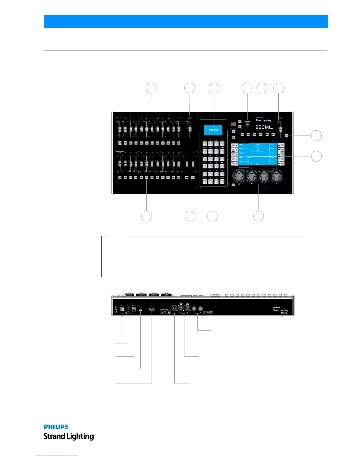
Basic Console Layout................................................................................................................................................................. 6
Console Features and Connections............................................................................................................................................. 7
Power Switch...................................................................................................................................................................... 7
Power Input......................................................................................................................................................................... 7
Ethernet Port (RJ45) ........................................................................................................................................................... 7
Faceplate USB Port (Library Storage)................................................................................................................................ 7
Rear USB Port .................................................................................................................................................................... 7
VGA Out (Monitor)............................................................................................................................................................ 7
MIDI In/Thru...................................................................................................................................................................... 7
DMX512 In (1 Connection)................................................................................................................................................ 7
DMX512 Out (2 Connections) ........................................................................................................................................... 7
Connecting Power....................................................................................................................................................................... 7
Glossary of Terms....................................................................................................................................................................... 7
Text Conventions........................................................................................................................................................................ 9
CONSOLE SETUP
Main Menu................................................................................................................................................................................ 10
Setup ................................................................................................................................................................................. 10
Record Options ................................................................................................................................................................. 10
Lock/Unlock ..................................................................................................................................................................... 11
MIDI Setup ....................................................................................................................................................................... 11
Playback Setup.................................................................................................................................................................. 12
DMX In Setup................................................................................................................................................................... 13
Display Setup.................................................................................................................................................................... 13
Patch.......................................................................................................................................................................................... 13
Patching Conventions....................................................................................................................................................... 15
Patch Screen...................................................................................................................................................................... 16
Viewing Patch................................................................................................................................................................... 16
Range Patching ................................................................................................................................................................. 17
Removing Patching Assignment....................................................................................................................................... 17
Patching Intelligent Fixtures............................................................................................................................................. 17
Patch/Unpatch Fixture to DMX Address.......................................................................................................................... 18
Fixture Pages..................................................................................................................................................................... 20
Pan/Tilt Options................................................................................................................................................................ 20
OPERATION
Console VGA Monitor Display Attributes............................................................................................................................... 22
Console 7-Inch Display Attributes ........................................................................................................................................... 23
Channels and Channel Levels................................................................................................................................................... 23
Assigning Channel Levels ................................................................................................................................................ 23
Intensity on Encoder......................................................................................................................................................... 24
Releasing Channels........................................................................................................................................................... 24
Recording A Cue ...................................................................................................................................................................... 24
Cue Options ...................................................................................................................................................................... 25
Record (Minus Subs) Cue................................................................................................................................................. 27
Running a Cue .......................................................................................................................................................................... 27
# Pausing A Cue ....................................................................................................................................................................... 27
Playback Operation................................................................................................................................................................... 27
Cue List..................................................................................................................................................................................... 28
Cue List Options............................................................................................................................................................... 29

4
250ML Lighting Control Consoles Operation Guide
Recording a Submaster............................................................................................................................................................. 30
Submaster Pages ............................................................................................................................................................... 30
Submaster Options............................................................................................................................................................ 31
Record (Minus Subs) Submaster .............................................................................................................................................. 34
Recording a Playback ............................................................................................................................................................... 35
Record Playback Options.................................................................................................................................................. 36
Recording an Effect .................................................................................................................................................................. 37
Record Effect Options ...................................................................................................................................................... 38
Cue/Submaster Preview............................................................................................................................................................ 39
Submaster List .......................................................................................................................................................................... 40
Editing a Submaster.......................................................................................................................................................... 40
Editing a Submaster Effect ............................................................................................................................................... 41
Edit a Submaster Playback ............................................................................................................................................... 42
FX List...................................................................................................................................................................................... 43
Recording a Group.................................................................................................................................................................... 43
Applying Groups....................................................................................................................................................................... 43
Basic Automated Luminaire Control........................................................................................................................................ 43
Home................................................................................................................................................................................. 44
Paging the Fixture Display ............................................................................................................................................... 45
Tagging and Untagging .................................................................................................................................................... 45
Palettes...................................................................................................................................................................................... 45
Recording a Palette........................................................................................................................................................... 46
Applying A Palette............................................................................................................................................................ 46
Accessing Fixtures using Channel Numbers.................................................................................................................... 47
Focus......................................................................................................................................................................................... 47
S9-Show List..................................................................................................................................................................... 48
Automated Luminaire Effects................................................................................................................................................... 48
Archive...................................................................................................................................................................................... 49
Save Show......................................................................................................................................................................... 49
Clear Memory / Subs........................................................................................................................................................ 50
Clear Palettes .................................................................................................................................................................... 50
Default Setup .................................................................................................................................................................... 51
Load Show........................................................................................................................................................................ 51
Effects Tutorial ......................................................................................................................................................................... 52
Creating an Intensity Effect.............................................................................................................................................. 52
MAINTENANCE
Reset Desk ................................................................................................................................................................................ 54
Update Software ....................................................................................................................................................................... 54
Update VGA Screen ................................................................................................................................................................. 55
Test Mode ................................................................................................................................................................................. 56
PRODUCT INFORMATION
Specification ............................................................................................................................................................................. 57
Console Capacities.................................................................................................................................................................... 58
Principle Features ..................................................................................................................................................................... 58

Operation Guide 250ML Lighting Control Consoles
5PREFACE
PREFACE
1. About this Guide
Congratulations on your purchase of your Philips Strand Lighting 250ML Control Console. It is a compact lighting
control console, versatile, powerful, and the perfect desk to introduce you to the world of intelligent fixture control.
Every unit has been thoroughly tested and carefully packed before shipment.
Unpack the shipping carton carefully, saving the carton and all packing materials for
possible later use. Refer to"Included Items" for a complete list of items and accessories
that are provided as part of your console.
Note: Check carefully that your product has not been damaged and that there are no
accessories missing. If your product appears to be damaged or missing any accessories,
please do not use the console and contact your Authorized Philips Strand Lighting Dealer
immediately.
Please read this manual carefully and thoroughly, as it gives important information
regarding safety, use and maintenance. Keep this manual with the console for possible
future reference.
You can use the QR code (to the right) on any QR code enabled smartphone to connect directly to the 250ML Control
Console product page and download the product manual or other product data.
Note: This version of the Operation Guide covers software version 1.1.x. Should your 250ML Control Console need
to be upgraded, go to www.strandlighting.com and click on the product downloads area in the Support section for the
latest software available.
2. Included Items
Each 250ML Lighting Control Console includes the following items:
• Lighting control console (with integrated video [VGA] card)
• Console dust cover
• Universal voltage power supply
• USB key drive
•LEDdesklamp
• 250ML Console QuickStart Guide (not this document)
Note: Monitors, cables and other accessories are not included and are sold separately. For available accessories,
please contact you local Authorized Strand Lighting Dealer. A list of Authorized Dealers is located on the Strand
Lighting web site at www.strandlighting.com.
250ML Control Console
Product Page

Basic Console Layout 6
250ML Lighting Control Consoles Operation Guide
OVERVIEW
1. Basic Console Layout
Power Switch
DMX512A (RDM) Out
(2 each)
DMX512A (RDM) In
VGA Out
(Monitor)
Power Input
Ethernet Port (RJ45)
USB Port *
MIDI In/Thru
250ML Console - Rear Panel Connections
A B C D F
G
H
I
E
JL K
A. 24 Faders / Submasters
B. Playback Master
C. Programming LCD Display
D. USB Port (showfile storage, USB key sold separately)
E. Main Console LCD Color Display
F. Grand Master
G. Black Out Button
H. Softkeys (10 each)
I. Encoders (4 each)
J. Programming Buttons
K. A / B Playback Controls (with Go and Load buttons)
L. 24 Bump Buttons
Legend
(*For USB LED desk lamp. Not for showfile storage.)
THRU
MIDI T HRU

Operation Guide 250ML Lighting Control Consoles
7OVERVIEW
2. Console Features and Connections
Power Switch
Turns console On or Off. Note, turning off this switch does not disconnect power from console.
Power Input
Power into console from universal (AC to DC) power supply. Refer to the QuickStart guide supplied with console on
how to connect power using provided power supply. The power supply shipped with your 250ML Control Console is
an auto-ranging, universal voltage supply. It operates between 90 to 240 VAC.
Ethernet Port (RJ45)
For future expansion of Ethernet protocols.
Faceplate USB Port (Library Storage)
USB connection for connection of a USB drive to load libraries, save shows, or update console software.
Rear USB Port
USB port for connection of USB LED desk lamp connection. Not for showfile storage.
VGA Out (Monitor)
VGA connection for driving a VGA video monitor. Refer to the QuickStart guide supplied with console for VGA
connections. Note, video monitor sold separately.
MIDI In/Thru
The console provides two standard 6-pin MIDI connectors. The MIDI In can connect to a MIDI generator and the
MIDI Thru can connect to another MIDI device.
DMX512 In (1 Connection)
DMX512 input connection for DMX512 signals from another console or device.
DMX512 Out (2 Connections)
The console provides two standard, female XLR 5-pin connector for connecting to, and controlling, DMX512
devices. DMX512 is for outputting to a universe of DMX devices for your primary output. This can include dimmers,
LED fixtures, and moving lights.
Note: For more information on DMX512, refer to "Additional Resources for DMX512" on page 2.
3. Connecting Power
To connect the power supply:
Step 1. Make sure unit's power switch is set to "Off"
Step 2. Connect DC connector from power supply to DC IN on console.
Step 3. Connect power supply to AC supply source.
Step 4. Turn on console at Console On / Off Switch.
Note: You must connect the console to the lighting system via DMX512 before it is capable of providing control.
Refer to the QuickStart Guide provided with the console for DMX512 connection information.
4. Glossary of Terms
This section covers some of the common terms used throughout this manual.
•Fader / Submaster / Playback - Slider hardware to control the level of stored information.
•Fader / Submaster / Playback Bump Button - button hardware that activates the stored information
on the submaster or playback.
•Playback Master - a master inhibitive slider for all playback data.

Glossary of Terms 8
250ML Lighting Control Consoles Operation Guide
•A and B Master - master inhibitive sliders for A and B playbacks. A is at 100% at the top end of its travel
while the B is at 100% at the bottom end of its travel. This allows the execution of dipless crossfades by moving
both sliders in the same direction.
•GO - advances the next available cue.
•LOAD - allows the preparation for the next cue advanced by the [GO] button.
•Programming LCD Display- this small LCD display will display pertinent information based on the active
item being programmed or played back. This screen also shows the function of the four softkeys labeled (F1) -
(F4).
•Programming Buttons - these allow for traditional Command Line operation for setting levels and storing
items like Cues and Subs.
•Record - command used to store information.
•Cue - cues are items to be played back in time and in sequential order.
•ON - level of 100%. Example: [1] [ON]
•Thru - allows a collection of a range of channels. Example: [1] [THRU] [5] [ON].
•0 thru 9 - numerical entry key for Command Line operation.
•Plus "+" - allows the addition of channels to a Command Line string. Example: [1] [+] [2] [ON]. Also if pressed
without a pre-existing channel list, it will Page Up the channel display. If the Fixture button is selected, it will Page
Up the Fixture display.
•Minus "-"- allows the subtraction of channels to a Command Line string. Example: [1] [THRU] [5] [-] [3] [ON].
This will place 1, 2, 4, and 5 at Full. Also if pressed without a pre-existing channel list, it will Page Down the chan-
nel display. If the Fixture button is selected, it will Page Down the Fixture display.
•AT "@" - command that tells the desk that the next numerical entry is a level of brightness. Example: [1] [@] [5]
[0] [ENTER].
•CLR - clears the Command Line plus releases channels. CLR will remove the last command entered into the
Command Line. In the event that there is nothing entered into the Command Line, [CLR] [CLR] will release all
Selected Channels (in the Red Box) a third [CLR] shall release all Adjusted Channels (Red Text).
•Decimal "." - allows the entry of DMX values rather than percentage values. Example: [1] [@] [.] [2] [5] [5]
[ENTER].
•ENTER - allows the completion of any command entered into the Command Line. Example: [1] [@] [5] [0]
[ENTER], [RECORD] [CUE] [1] [ENTER].
•Arrow Up and Arrow Down (adjacent to the small LCD screen) - Allows the ability to change pages.
•Untag - This button has multiple functions. It can untag (deselect) fixtures, attribute families or individual
attributes. See Tagging and Untagging for details. Selecting SHIFT + UNTAG allows the user entry in the Setup
pages for system configuration settings.
•Home - sets the channel or fixture back to its default position.
•Fixture- fixture is the term for attributed luminaires (LEDs and Moving Lights). This button allows access to the
patched attributed luminaires.
•Position - allows access to programming for position attributes on an attributed luminaire.
•Color - allows access to programming for color attributes on an attributed luminaire.
•Beam - allows access to programming for beam parameters on an attributed luminaire.
•Effect - allows access to programming for effect parameters on an attributed luminaire.
•Group - Allows access to programming a collection of channels or fixtures.
•Grand Master - an inhibitive master for all outputting intensity levels.
•Blackout Button - single button access that will set all outputting intensity levels to zero.

Operation Guide 250ML Lighting Control Consoles
9OVERVIEW
•Main Console LCD Display - primary programming display. This 7-inch color display will display the
Command Line, recording commands, all configuration information, 10 softkey labels and 4 encoder's informa-
tion.
•Shift - used to gain access to the Setup environment as well as access to additional advanced commands.
•Shift + UNTAG = Setup
•Shift + ENTER= Encoder Intensity control on selected channels.
•Shift + Encoders = can gain access to advanced features on some items. For example, on Fade Up /
Fade Down this will allow for time adjustment in 1/10th second.
5. Text Conventions
When a key is referred to in the manual it will be in hard brackets. For instance [RECORD] would refer to the record
button. A softkey command on the LCD screen will be written inside ( ). So for instance the (S9-Enter) would refer to
a softkey option available on the LCD screen. For operational information, refer to "OPERATION" on page 22.
The example in Figure 1 represents any command button like Record used in teaching examples.
Figure 1: Command Button Example
The example in Figure 2 represents any bump button or softkey used in teaching examples.
Figure 2: Bump Button Example

Main Menu 10
250ML Lighting Control Consoles Operation Guide
CONSOLE SETUP
1. Main Menu
Holding down the [SHIFT] + [UNTAG] for 3 seconds will launch into the Setup portion of the 250ML Console.
Figure 3: Main Menu
The following options are available for the 250ML Control Console:
Setup
(S1 - Setup): Setup allows the user to adjust the console to work the way that's most comfortable for the user. Any
options within the main screen on the Setup Menu can be navigated to using Encoder D to scroll Up/Down the list of
setup options.
Figure 4: Setup Menu
Within Setup, there are options that determine how the console functions. The setup options are…
Record Options
Record Options determine how the record action works. By default the Mode (which refers to the Record Mode is set
to Full. That means that everything that is being outputted from the console will be stored. By pressing S1 the Mode
can be changed. If the Mode is set to Partial, then the other softkeys shall control how Brightness (Intensity), Color,
Beamshape and Position parameters shall be stored.
Figure 5: Record Options

Operation Guide 250ML Lighting Control Consoles
11 CONSOLE SETUP
When the attribute family (Position, Color or Beam) option is set to ALL, then when one parameter is adjusted, all
parameters for that family will be highlighted to be stored. For example, if programming color on a 3 color LED and
the Red is adjusted, the Green and Blue will be highlighted as well.
When the attribute family option is set to CHANNEL, then when one parameter is adjusted, only that parameter will
be highlighted to be stored. For example, if programming color on a 3 color LED and the Red is adjusted, the Green
and Blue will not be highlighted.
Lock/Unlock
This features allows the locking and unlocking of the console from any accidental use.
Use Encoder D to scroll down to <Lock/Unlock>, press down on Encoder D and the Lock/Unlock option will appear.
This is password protected and the password must be entered to engage/disengage this feature.
Note: The password is 168168.
Figure 6: Lock Console Screen
MIDI Setup
This feature allows the console to communicate with other consoles using the MIDI interface. MIDI In and Thru are
available. Just connect a standard MIDI cable from a third party console to the 250ML console's MIDI In port. If you
need to communicate to a third console, a MIDI cable can be connected from the 250ML console's MIDI Thru port to
another third party console.
Figure 7: MIDI Setup Screen
• From the MIDI Setup screen, S1 will Enable MIDI while S2 will disable MIDI.
• Encoder A will configure the Channel (0 - 15) and Encoder D will configure the Note (0 - 127).
Note: There are different types of MIDI messages. The only one that the 250ML supports is Channel Voice. The
Channel setting allows the console to listen to any channel from 0 to 15. The Note variable allows the console to
listen to individual Voice Channels 0 to 127. This will control channels but not cues or submasters.
As shown in Table 1, “MIDI Messages - Available Notes,” on page 12, there are a variety of notes available.

Main Menu 12
250ML Lighting Control Consoles Operation Guide
Table 1: MIDI Messages - Available Notes
Playback Setup
This setting determines how the last cue in the playback responds when run sequentially.
Figure 8: Playback Setup Screen
The options are:
• (S1-PB Cue Release) whereby the last cue will be released from the playback.
• (S2-PB Cue Last Hold) whereby the playback will hold the last outputted value.
Notes DMX Channel Notes DMX Channel Notes DMX Channel Notes DMX Channel
Note 0 C-2 Channel 1 Note 32 G#0 Channel 33 Note 64 E3 Channel 65 Note 96 C6 Channel 97
Note 1 C#-2 Channel 2 Note 33 A 0 Channel 34 Note 65 F3 Channel 66 Note 97 C#6 Channel 98
Note 2 D-2 Channel 3 Note 34 A#0 Channel 35 Note 66 F#3 Channel 67 Note 98 D6 Channel 99
Note 3 D#-2 Channel 4 Note 35 B0 Channel 36 Note 67 G3 Channel 68 Note 99 D#6 Channel 100
Note 4 E-2 Channel 5 Note 36 C1 Channel 37 Note 68 G#3 Channel 69 Note 100 E6 Channel 101
Note 5 F-2 Channel 6 Note 37 C#1 Channel 38 Note 69 A3 Channel 70 Note 101 F6 Channel 102
Note 6 F#-2 Channel 7 Note 38 D1 Channel 39 Note 70 A#3 Channel 71 Note 102 F#6 Channel 103
Note 7 G-2 Channel 8 Note 39 D#1 Channel 40 Note 71 B3 Channel 72 Note 103 G6 Channel 104
Note 8 G#-2 Channel 9 Note 40 E1 Channel 41 Note 72 C4 Channel 73 Note 104 G#6 Channel 105
Note 9 A-2 Channel 10 Note 41 F1 Channel 42 Note 73 C#4 Channel 74 Note 105 A6 Channel 106
Note 10 A#-2 Channel 11 Note 42 F# 1 Channel 43 Note 74 D4 Channel 75 Note 106 A#6 Channel 107
Note 11 B-2 Channel 12 Note 43 G1 Channel 44 Note 75 D#4 Channel 76 Note 107 B6 Channel 108
Note 12 C-1 Channel 13 Note 44 G#1 Channel 45 Note 76 E4 Channel 77 Note 108 C7 Channel 109
Note 13 C#-1 Channel 14 Note 45 A1 Channel 46 Note 77 F4 Channel 78 Note 109 C#7 Channel 110
Note 14 D-1 Channel 15 Note 46 A#1 Channel 47 Note 78 F#4 Channel 79 Note 110 D7 Channel 111
Note 15 D#-1 Channel 16 Note 47 B1 Channel 48 Note 79 G4 Channel 80 Note 111 D#7 Channel 112
Note 16 E-1 Channel 17 Note 48 C2 Channel 49 Note 80 G#4 Channel 81 Note 112 E7 Channel 113
Note 17 F-1 Channel 18 Note 49 C#2 Channel 50 Note 81 A4 Channel 82 Note 113 F7 Channel 114
Note 18 F#-1 Channel 19 Note 50 D2 Channel 51 Note 82 A#4 Channel 83 Note 114 F#7 Channel 115
Note 19 G-1 Channel 20 Note 51 D#2 Channel 52 Note 83 B4 Channel 84 Note 115 G7 Channel 116
Note 20 G#-1 Channel 21 Note 52 E2 Channel 53 Note 84 C5 Channel 85 Note 116 G#7 Channel 117
Note 21 A-1 Channel 22 Note 53 F2 Channel 54 Note 85 C#5 Channel 86 Note 117 A7 Channel 118
Note 22 A#-1 Channel 23 Note 54 F#2 Channel 55 Note 86 D5 Channel 87 Note 118 A#7 Channel 119
Note 23 B-1 Channel 24 Note 55 G2 Channel 56 Note 87 D#5 Channel 88 Note 119 B7 Channel 120
Note 24 C 0 Channel 25 Note 56 G#2 Channel 57 Note 88 E5 Channel 89 Note 120 C8 Channel 121
Note 25 C# 0 Channel 26 Note 57 A2 Channel 58 Note 89 F5 Channel 90 Note 121C#8 Channel 122
Note 26 D0 Channel 27 Note 58 A#2 Channel 59 Note 90 F#5 Channel 91 Note 122 D8 Channel 123
Note 27 D#0 Channel 28 Note 59 B2 Channel 60 Note 91 G5 Channel 92 Note 123 D#8 Channel 124
Note 28 E0 Channel 29 Note 60 C3 Channel 61 Note 92 G#5 Channel 93 Note 124 E8 Channel 125
Note 29 F0 Channel 30 Note 61 C#3 Channel 62 Note 93 A5 Channel 94 Note 125 F8 Channel 126
Note 30 F# 0 Channel 31 Note 62 D3 Channel 63 Note 94 A#5 Channel 95 Note 126 F#8 Channel 127
Note 31 G0 Channel 32 Note 63 D#3 Channel 64 Note 95 B5 Channel 96 Note 127 G8 Channel 128

Operation Guide 250ML Lighting Control Consoles
13 CONSOLE SETUP
DMX In Setup
This option turns on the DMX In port on the back of the console to allow another DMX control device (like a
console) to affect changes on the 250ML Control Console.
Figure 9: DMX In Setup Screen
The options are:
• (S1-DMX In Enable) - enable DMX input signals from another DMX control source.
• (S2-DMX In Disable) - disables DMX input signals from another DMX control source.
Once DMX In is enabled and a DMX512 cable has been connected from the DMX512 Out port on the external
console to the DMX In port of the 250ML console, the external console will control the first 96 channels in a 1 to 1
fashion. For example, Channel 1 on the external console will control Channel 1 on the 250ML console and continue
in numerical sequence up to a capacity of 96 channels.
Display Setup
Allows the adjustment of the backlight level settings for the color display screen on the console.
Figure 10: Display Setup Screen
The options are:
• (S1-Backlight High) - sets console display to highest brightness level.
• (S2-Backlight Medium) - sets console display to the medium brightness level.
• (S3-Backlight Low) - sets console display to lowest brightness level.
2. Patch
Patch allows the operator to determine the channel and fixture numbers that control each DMX channel whether they
are a dimmer or an automated luminaire such as an LED or moving light.
The 250ML Control Console starts out with a one-to-one default patch for the capacity of the console and no
automated luminaires patched. That's 250 channels. A one-to-one patch means that each dimmer will be patched and
controlled by a channel that is the same number. Example: Dimmer 1 is controlled by Channel 1, Dimmer 2 by
Channel 2 and so on up to Dimmer 250 being controlled by Channel 250.
Patching conventional channels on the 250ML Control Console is accomplished with Setup. Press [SHIFT] +
[UNTAG] to go into the Setup menu.

Patch 14
250ML Lighting Control Consoles Operation Guide
Press S2- Patch to go into the Patch menu.
Figure 11: Patch Menu

Operation Guide 250ML Lighting Control Consoles
15 CONSOLE SETUP
Patching Conventions
Use Encoder D to roll the selector up/down to DMX Patch (the active option will be in a white background) and click
on Encoder D to select DMX Patch. The monitor will now display the patch screen to show what the current channel
assignments are. As shown in Figure 12, the DMX output number is the top line in white and the second line is the
control channel in yellow.
Figure 12: VGA Patch Screen
Note: After 250 you only see the DMX output numbers displayed. Remember that the console has a limit of 250
control channels.

Patch 16
250ML Lighting Control Consoles Operation Guide
Patch Screen
The Patch screen is the point of information for all DMX output assignments. Pressing [F3 – Patch] will open the
patch screen on the VGA monitor. From the Patch Screen, [+] and [–] will page the patch screen to view all DMX
outputs from 1 to 1024 and their patch assignment. DMX512 Port A will output 1 thru 512. The first universe of
DMX. DMX512 Port B will output 513 to 1024. The second universe of DMX.
Figure 13: Patch Screen
This is for display only. Any patch adjustment shall be done thru Setup and instructions can be found in "Setup" on
page 10.
Viewing Patch
Patch can be viewed at anytime, whether in the Setup screen for patching activities or not. In many screens, the F
keys will give you a Patch option. When the F key for Patch is pressed, the patch screen above will be displayed. The
[+] and [-] keys will advance the patch screens to show you all 1024 patch outputs. Pressing the F key for Patch will
return the console to the previous screen.
While in the Patch Menu, the F keys will access paging the patch screen with [PATCH +] and [PATCH -].
In order to change the default patch, direct your attention to the color screen on the console as illustrated in Figure
14.
Figure 14: Console LCD Patch Menu
The second option (and the examples) focus on using Command Line to patch. The syntax will be [DIMMER] [@]
[CHANNEL] so if you need dimmer 2 to be controlled by channel 1, type [2] [@] [1] [ENTER]. Once that is done,
the channel number (yellow) will have changed under dimmer 2 to reflect its assignment to channel 1. Any patching
done will appear in the Command Line section of the color screen. Just repeat this process for any non-default
patching that is required. Notice that you can use THRU, + and - to speed up the patching process.

Operation Guide 250ML Lighting Control Consoles
17 CONSOLE SETUP
Range Patching
Range patching allows the patching of multiple dimmers and multiple channels using a single command. Below are
some examples of range patching.
Should you need multiple dimmers controlled by the same channel, [DIMMER] [THRU] [DIMMER] [@]
[CHANNEL] [ENTER]. Example: [1] [THRU] [5] [@] [1] [ENTER] will patch dimmers 1 thru 5 to channel 1.
Should you need a consecutive dimmer range to be patched to a consecutive channel range, [DIMMER] [THRU]
[DIMMER] [@] [CHANNEL] [THRU] [CHANNEL] [ENTER]. Example: [1] [THRU] [5] [@] [11] [THRU] [15]
[ENTER] will patch dimmer 1 to channel 11, dimmer 2 to channel 12 and so on for the range limit that was entered.
Removing Patching Assignment
To remove any patch assignment to any dimmer, just type [DIMMER] [@] [ENTER]. This will remove any channel
assignment to the selected dimmer and any previous channel number (yellow) will be removed. Notice that [THRU],
[+] and [-] will help you speed up the patching process.
Note: Refer to "Range Patching" (above) on how to use [THRU], [+] and [-].
Patching Intelligent Fixtures
Intelligent fixtures such as LEDs and Moving Lights require a more sophisticated control system and the 250ML
Control Console has everything you need to get started with intelligent fixture control.
Note: There is a limit of 30 intelligent fixtures and 40 parameter capacity on the 250ML Control Console.
From the Setup menu (hold [SHIFT] + [UNTAG] for 3 seconds), press (S2 - Patch) and roll Encoder D clockwise to
move the cursor (white background) down to "Assign Fixture" and press the Encoder D to select.
Figure 15: Patching Intelligent Fixtures - Fixture Screen
From the fixture screen, select Encode D to Add a fixture.
Figure 16: Patching Intelligent Fixtures - Fixture Screen (Adding a Fixture)

Patch 18
250ML Lighting Control Consoles Operation Guide
Fixtures are added from the 250ML Fixture Library via a USB key. The fixture library can be downloaded from
www.strandlighting.com in the Support section. Select (S8 - Open) USB Library.
Figure 17: Patching Intelligent Fixtures - Fixture Library
The manufacturers shall appear on the S keys. Philips companies are on the left and other manufacturers are on the
right. If you don't see the manufacturer on the existing softkeys, just roll Encoder D to advance the non-Philips
manufacturer on the right and press the appropriate softkey. Once a manufacturer is selected, the manufacturer's
models will appear in the center of the color screen. Rolling Encoder D up / down shall highlight each fixture type.
Press Encoder D to select the appropriate fixture model.
Figure 18: Patching Intelligent Fixtures - Selecting a Fixture from Fixture Library
Now a location must be selected for the fixture. These will be accessed by the softkeys. It is recommended that you
start with S1, but you can select any softkey. When the appropriate softkey is selected (it will be lit red) select
Encoder D to "assign" the fixture. Once that is complete, the name will appear for the softkey.
Now that particular fixture is assigned to a softkey, patching subsequent fixtures shall appear in "My Favorites" and
the USB key with the fixture library shall only be needed to add a different model fixture.
Patch/Unpatch Fixture to DMX Address
Now that the appropriate fixture has been assigned, it must still be assigned a DMX address in order for it to function.
Select Encoder A to restore to the Setup screen.
Select (S2 - Patch) and then the first option of DMX Patch with rolling Encoder D to the correct option and pressing
Encoder D to select.
Figure 19: Patch/Unpatch Fixture to DMX Address

Operation Guide 250ML Lighting Control Consoles
19 CONSOLE SETUP
You will see the Patch menu but the newly assigned intelligent fixture shall be available on the appropriate softkey. In
this case, (S1). Select (S1).
Figure 20: Patch Menu - Patching Fixtures Screen
Select (S6 - Add).
Note: If you are clearing out the DMX assignment of a particular fixture, pressing (S7 - Delete) will accomplish this.
Figure 21: Patch Menu - Assigning Fixtures
Select (S1 - Line 1) for the first universe of DMX512. This will be 1 thru 512.
Select (S2 - Line 2) for the second universe of DMX512. This will be 513 thru 1024.
Notice that the first available DMX512 address is automatically populated on the command line. That's 251 for DMX
universe 1 and 513 for DMX universe 2.
To accept the default press [ENTER].
Table of contents
Other Philips Music Mixer manuals

Philips
Philips D 6560 User manual

Philips
Philips Strand Lighting User manual

Philips
Philips SOPHO SuperVisor 25 Quick start guide

Philips
Philips D 6560 User manual

Philips
Philips CD 6660 User manual

Philips
Philips Strand Lighting 100 plus series Installation manual

Philips
Philips 200 series User manual

Philips
Philips Palette VL64 Assembly instructions

Philips
Philips 64331 User manual