Philips Strand Lighting 100 plus series Installation manual


Strand Lighting Locations
The material in this manual is for information purposes only and is subject to change without notice. Philips Strand
Lighting assumes no responsibility for any errors or omissions which may appear in this manual. For comments and
suggestions regarding corrections and/or updates to this manual, please visit the Philips Strand Lighting web site at
www.strandlighting.com or contact your nearest Philips Strand Lighting office.
El contenido de este manual es solamente para información y está sujeto a cambios sin previo aviso. Philips Strand
Lighting no asume responsabilidad por errores o omisiones que puedan aparecer. Cualquier comentario, sugerencia
o corrección con respecto a este manual, favor de dirijirlo a la oficina de Philips Strand Lighting más cercana.
Der Inhalt dieses Handbuches ist nur für Informationszwecke gedacht, Aenderungen sind vorbehalten. Philips
Strand Lighting uebernimmt keine Verantwortung für Fehler oder Irrtuemer, die in diesem Handbuch auftreten. Für
Bemerkungen und Verbesserungsvorschlaege oder Vorschlaege in Bezug auf Korrekturen und/oder
Aktualisierungen in diesem Handbuch, moechten wir Sie bitten, Kontakt mit der naechsten Philips Strand Lighting
Niederlassung aufzunehmen.
Le matériel décrit dans ce manuel est pour information seulement et est sujet à changements sans préavis. La
compagnie Philips Strand Lighting n'assume aucune responsibilité sur toute erreur ou ommission inscrite dans ce
manuel. Pour tous commentaires ou suggestions concernant des corrections et/ou les mises à jour de ce manuel,
veuillez s'il vous plait contacter le bureau de Philips Strand Lighting le plus proche.
Note: Information contained in this document may not be duplicated in full or in part by any person without prior written
approval of Philips Strand Lighting. Its sole purpose is to provide the user with conceptual information on the equipment
mentioned. The use of this document for all other purposes is specifically prohibited.
Document Number: STR-61318
Version as of: 02 November 2010
100 Plus Series Console Operations Manual
©2010 Philips Group. All rights reserved.
Philips Strand Lighting - Dallas
10911 Petal Street
Dallas, TX 75238
Tel: 214-647-7880
Fax: 214-647-8031
Philips Strand Lighting - Auckland
19-21 Kawana Street
Northcote, Auckland 0627
New Zealand
Tel: +64 9 481 0100
Fax: +64 9 481 0101
Philips Strand Lighting - New York
267 5th Ave, 4th Floor
New York, NY 10016
Tel: 212-213-8219
Fax: 212-532-2593
Philips Strand Lighting - Europe
Marssteden 152
Enschede 7547 TD
The Netherlands
Tel: +31 53 4500424
Fax: +31 53 4500425
Philips Strand Lighting - Asia Limited
Room 6-10, 20/F Delta House 3 On Yiu Street
Shatin, N.T. Hong Kong
Tel: + 852 2757 3033
Fax: + 852 2757 1767
Website:
www.strandlighting.com

1
100 Plus Series Console
IMPORTANT INFORMATION
Warnings and Notices
Additional Resources for DMX512
For more information on installing DMX512 control systems, the following publication is available for purchase
from the United States Institute for Theatre Technology (USITT), "Recommended Practice for DMX512: A Guide
for Users and Installers, 2nd edition" (ISBN: 9780955703522). USITT Contact Information:
USITT
6443 Ridings Road
Syracuse, NY 13206-1111 USA
1-800-93USITT
www.usitt.org
Philips Strand Lighting Limited Two-Year Warranty
Philips Strand Lighting offers a two-year limited warranty of its products against defects in materials or
workmanship from the date of delivery. A copy of Philips Strand Lighting two-year limited warranty containing
specific terms and conditions can be obtained from the Philips Strand Lighting web site at www.strandlighting.com
or by contacting your local Philips Strand Lighting office.
When using electrical equipment, basic safety precautions should always be followed including the following:
a. READ AND FOLLOW ALL SAFETY INSTRUCTIONS.
b. Do not use outdoors.
c. Do not use near gas or electric heaters.
d. The use of accessory equipment not recommended by the manufacturer may cause an unsafe
condition.
e. Do not use this equipment for other than intended use.
f. Refer service to qualified personnel.
SAVE THESE INSTRUCTIONS.
WARNING: You must have access to a main circuit breaker or other power disconnect device
before installing any wiring. Be sure that power is disconnected by removing fuses or turning the
main circuit breaker off before installation. Installing the device with power on may expose you to
dangerous voltages and damage the device. A qualified electrician must perform this installation.
WARNING: Do not open the console. There are no user serviceable parts inside. This equipment is
designed to operate from the mains electrical supply and contains voltages, which, if touched, may
cause death or injury. It should only be operated in accordance with the instructions provided and for
the purpose of a lighting control system.
WARNING: Avoid spilling liquid on the equipment If this should happen, switch the equipment off
immediately at the mains. To reduce the risk of fire or electric shock, do not expose the equipment to
rain or moisture. For indoor use only.
WARNING: Refer to National Electrical Code® and local codes for proper use specifications.
WARNING: This equipment is intended for use in accordance with the National Electric Code® and
local regulations. It is also intended for installation in indoor applications only. Before any electrical
work is performed, disconnect power at the circuit breaker or remove the fuse to avoid shock or
damage to the control. It is recommended that a qualified electrician perform this installation.

Operations Manual
2TABLE OF CONTENTS
TABLE OF CONTENTS
Strand Lighting Locations................................................................................................... Inside Front Cover
IMPORTANT INFORMATION
Warnings and Notices...................................................................................................................................... 1
Additional Resources for DMX512................................................................................................................. 1
Philips Strand Lighting Limited Two-Year Warranty..................................................................................... 1
TABLE OF CONTENTS
PREFACE
About this Guide..................................................................................................................................................... 3
Product Description................................................................................................................................................ 3
Compliance Information......................................................................................................................................... 3
Included Items ........................................................................................................................................................ 3
INTRODUCTION
100 Plus Series Console Layout............................................................................................................................. 4
Glossary of Terms................................................................................................................................................... 4
Getting Started........................................................................................................................................................ 6
Site Requirements............................................................................................................................................ 6
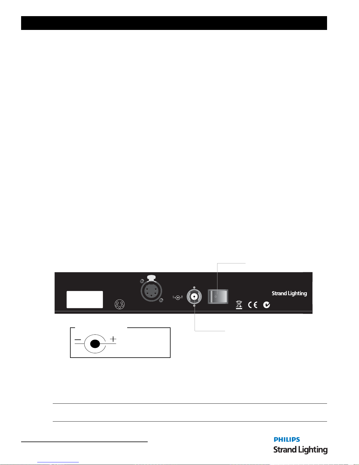
Connecting Power ........................................................................................................................................... 6
Connecting DMX512 ...................................................................................................................................... 7
Rack Mounting ....................................................................................................................................................... 7
Product Care ........................................................................................................................................................... 8
Customer Service and Support ............................................................................................................................... 8
CONSOLE OPERATION
Two Scene Operation.............................................................................................................................................. 9
Manual Crossfades.................................................................................................................................................. 9
Timed Crossfades ................................................................................................................................................. 10
Single Scene Operation......................................................................................................................................... 10
Hold ...................................................................................................................................................................... 11
Effect - Single Scene Mode.................................................................................................................................. 11
Effect - Two Scene Mode ..................................................................................................................................... 12
Memory Operation................................................................................................................................................ 13
Record Mode................................................................................................................................................. 13
Playback Mode.............................................................................................................................................. 14
Go Button Playback....................................................................................................................................... 14
Timed Playback............................................................................................................................................. 14
Preset Playback of Memories........................................................................................................................ 14
Timed Playback............................................................................................................................................. 14
Deleting Memories ............................................................................................................................................... 14
Single Memory Deletion ............................................................................................................................... 14
All Memory Deletion .................................................................................................................................... 15
Preview Recorded Memories................................................................................................................................ 15
TECHNICAL SPECIFICATIONS
Electrical............................................................................................................................................................... 16
Mechanical............................................................................................................................................................ 16

About this Guide 3
100 Plus Series Console
PREFACE
1. About this Guide
The document provides installation and operation instructions for the following product:
• 100 Plus Series Console
Please read all instructions before using this product. Retain this manual for future reference. Additional information
for Strand Lighting control consoles including product descriptions may be downloaded at www.strandlighting.com
2. Product Description
The Strand 100 series console is a small, simple to use, preset lighting desk. It can either control 24 channels in 1
scene or 12 channels in 2 scenes with the ability to expand scenes with the Hold feature. The console also has the
ability to run a single effect. It is also possible to program a single theatrical cue stack of 99 memories and play these
back. This console can be rack mounted. For complete technical specifications, see "TECHNICAL
SPECIFICATIONS" on page 16.
Figure 1: 100 Plus Series Console
3. Compliance Information
This equipment is designed and manufactured to comply with international safety standards 1EC950, UL1950,
CS950 and is intended for use as part of a lighting control system. It must not be used for other purposes where there
is a risk of safety to persons. The equipment contains power voltages, socket outlets shall be installed near to the
equipment and be easily accessible. All units are CE marked and include UL, cUL listed power supplies.
4. Included Items
Unpack the console from the packaging and check that the following components are contained within. If any parts
are missing, or damaged, please contact the carrier and your nearest Strand Lighting office.
• 100 Plus Series Console
• Universal Power Supply (90 to 240 VAC, auto-ranging)
• Dust cover
• Operation’s Manual (this document)
Working Voltage (Current) 100 - 120 VAC (2A) / 220 - 240 VAC (1A)
Frequency 50 / 60 Hz
Maximum Ambient Temperature 40oC (104oF) - Do not restrict ventilation

Operations Manual
4INTRODUCTION
INTRODUCTION
1. 100 Plus Series Console Layout
Figure 2 illustrates the layout of the control features of the 100 Plus Series Console.
Figure 2: 100 Plus Series Console Control Features
2. Glossary of Terms
This section covers some of the common terms used throughout this manual.
Grand Master
An inhibitive fader that proportionately controls all other faders. This determines maximum output of all faders at all
times. The grand master is always active.
Playback A
An inhibitive fader that proportionately controls all faders for the A scene.
Playback B / Effect Master
When not running the effect, an inhibitive fader that proportionately controls all faders for the B scene. When running
the effect, the fader is a inhibitive master for the effect.
0.1s
0.2s
0.5s
1s
1.5s
2s 2.5s
3s
3.5s
4s
4.5s
5s
SPEED
10
9
8
7
6
5
4
3
2
1
0
E FFECT
FORWARD REVERSE RANDOM BOUNCE
MEMO RY
RECORD PREVIEW
DE L
13 14 15 16 17 18 19 20 21 22 23 24
10
9
8
7
6
5
4
3
2
1
0
123456789101112
10
9
8
7
6
5
4
3
2
1
0
10
9
8
7
6
5
4
3
2
1
0
10
9
8
7
6
5
4
3
2
1
010
9
8
7
6
5
4
3
2
1
0
10
9
8
7
6
5
4
3
2
1
0
10
9
8
7
6
5
4
3
2
1
0
A
B
AB
GO
G RAND
MASTER
PRESET
Manual
2
5
10
15
30
45
1min.
2min.
3min.
4min.
5min.
FADE TIME
BLACKOUT
HOLD
OFF
CH 1-12
CH 13-24
TWO SCENE
SINGLE SCENE
MODE FLASH
Channel Fader
Channel LED Fade Time /
LED Display Blackout Button
Fader Flash Button Scene Master "A"
Scene Master "B"
Go Button
Grand Master
Effect Forward /
Hold or Delete
Scene or
FX Speed Rotary Effect Reverse /
Effect Random /
Effect Bounce /
Flash Mode
Memory Record
Memory Advance 1
Memory Back 1
Memory Preview
Memory Mode
Button
Button

Glossary of Terms 5
100 Plus Series Console
Channel Faders
A fader that controls the output of the corresponding dimmer number.
Fader Flash Button
A momentary button that flashes the level of the corresponding fader to full. Which fader is corresponding depends
on the setting of the FLASH BUTTON. See below.
Mode Button
A button that toggles between the three modes of operation of the console. 1 Scene 24 channel mode, 2 Scene 12
channel mode or Memory allows recording and playback of all 24 channels. (In memory Mode all buttons labeled in
blue text will perform the functions noted in blue.)
Hold Button
The Hold button will freeze the output of the faders so that the operator can reset the channel faders for a different
look. This is only available in single scene mode.
Flash Button Mode Button
There are only 12 fader flash buttons and this button toggles the fader flash buttons between OFF, faders 1 - 12 and
faders 13 - 24.
Fade Time / Effect Speed Dial
When not running the effect, this will allow the operator to set the fade time of the scene masters. When running the
effect, this will allow the operator to set the rate at which the effect is running. See the LED display for time / speed
readout.
Effect Options Buttons
These will allow the operator to change the stepping options of the effect. These buttons are only available in Two
Scene or Single Scene operation. Refer to Table 1 for more information.
Memory Options Buttons
These buttons will allow for programming and deletion of memories and for access specific numbers in the cue stack.
These buttons are only available in Memory Mode. Refer to Table 2 for more information.
Button Name Operation / Meaning
Forward Forward allows the faders that have a level to step
through their appropriate levels from the lowest
number fader number to the highest.
Reverse Reverse allows the faders that have a level to step
through their appropriate levels from the highest
number fader number to the lowest.
Random Random allows the faders that have a level to step
through their appropriate levels in a randomly
generated order.
Bounce
Bounce allows the faders that have a level to step
through their appropriate levels from the lowest
number fader number to the highest then back to the
lowest number fader.
Table 1: Effect Buttons
Button Name Operation / Meaning
Record Record allows the current output of the console to be
stored into a memory within the cue stack.
+ "+" (plus) will step the memory number forward by one
- "-" (minus) will step the memory number back by one
Preview Preview allows for a specific memory to be previewed.
Delete Delete allows for a memory or the whole cue stack to
be deleted.
Table 2: Memory Buttons

Operations Manual
6INTRODUCTION
LED Display
This will show alpha / numeric information about the console. Such as fade time, effect step rate, memory number
and whether the black out button is active.
LED Lights
All channel faders have LEDs that mimic the output level of each fader. LEDs also are indicators of the channel mode
as well as when all features are activated. All LEDs are green.
Black Out Button
This will allow the operator to instantly stop all fader output. Press again to restore fader output.
3. Getting Started
After unpacking the console and checking that you have all the included items shipped with your console (refer to
"Included Items" on page 3 for details), you may begin connecting your 100 Plus Series Console to power and
lighting system.
Site Requirements
The 100 Plus Series Console requires a sturdy, flat surface for installation (unless the unit is to be rack mounted - see
"Rack Mounting" on page 7 for information). The surface should be able to support the weight of the console and
should provide suitable ventilation. Also, the site should be clean (i.e. absent of any construction dust or debris) and
dry. Before setting up, ensure that the installation site meets these requirements. For operational and space
requirements, refer to "TECHNICAL SPECIFICATIONS" on page 16.
Connecting Power
The power supply shipped with your 100 Plus Series Console is an auto-ranging, universal voltage supply. It operates
between 90 to 240 VAC.
To connect the power supply:
Step 1. As shown in Figure 3, make sure unit’s power switch is set to "Off"
Step 2. Connect DC connector from power supply to DC IN on console.
Figure 3: 100 Plus Series Control Console Power Connection
Step 3. When DC connector is plugged in, twist it to lock in place.
Step 4. Connect power supply to AC supply source.
Step 5. Turn on console at Console On / Off Switch.
Note: You must connect the console to the lighting system via DMX512 before it is capable of providing control. See
"Connecting DMX512" on page 7 for more information.
PUSH
PUSH
PUSH
1
2
3
4
51
2
3
4
51
2
3
4
5
ON / OFF
DMX
OUTPUT
1 - Ground
2 - Data -
3 - Data +
4,5-NC
1
2
3
4
5
POWER
9-12VDC,
0.5A min.
RoHS
Made in P.R.C.
DC Input (from power supply)
Console On / Off Switch
100 Plus Series Console Rear Panel
9 to 12 Volts DC
0.5 Amps (min.)
DC Input
Connector Pinout

Rack Mounting 7
100 Plus Series Console
Connecting DMX512
The console provides one standard, female XLR 5-pin connector for connecting to DMX512 devices. This connector
supports one DMX512 universe of the first 24 channels.
Figure 4: 100 Plus Series Control Console DMX512 Connection
Note: For more information on DMX512, refer to "Additional Resources for DMX512" on page 1.
4. Rack Mounting
If you wish to mount the 100 Plus Series Console in a rack, using a Philips screwdriver, remove the hardware
securing the four side pieces around the console. Use the eight mounting holes (as shown in Figure 5) to secure the
console in a rack. Note, rack screws are not provided (by others).
Figure 5: 100 Plus Series Console Rack Mounting
Note: The 100 Plus Series Console should be rack mounted before power or DMX512 cables are connected.
PUSH
PUSH
PUSH
1
2
3
4
51
2
3
4
51
2
3
4
5
ON / OFF
DMX
OUTPUT
1 - Ground
2 - Data -
3 - Data +
4,5-NC
1
2
3
4
5
POWER
9-12VDC,
0.5A min.
RoHS
Made in P.R.C.
DMX512 Output Connector
100 Plus Series Console Rear Panel
DMX512 Output
Connector Pinout
1
2
4
5
3
Pin Signal
1 Ground
2 Data -
3 Data +
4 No Connection
5 No Connection
0.1s
0.2s
0.5s
1s
1.5s
2s 2.5s
3s
3.5s
4s
4.5s
5s
SPEED
10
9
8
7
6
5
4
3
2
1
0
E FFECT
FORWARD REVERSE RANDOM BOUNCE
MEMO RY
RECORD PREVIEW
DE L
13 14 15 16 17 18 19 20 21 22 23 24
10
9
8
7
6
5
4
3
2
1
0
123456789101112
10
9
8
7
6
5
4
3
2
1
0
10
9
8
7
6
5
4
3
2
1
0
10
9
8
7
6
5
4
3
2
1
010
9
8
7
6
5
4
3
2
1
0
10
9
8
7
6
5
4
3
2
1
0
10
9
8
7
6
5
4
3
2
1
0
A
B
AB
GO
G RAND
MASTER
PRESET
Manual
2
5
10
15
30
45
1min.
2min.
3min.
4min.
5min.
FADE TIME
BLACKOUT
HOLD
OFF
CH 1-12
CH 13-24
TWO SCENE
SINGLE SCENE
MODE FLASH
Rack Mount Mounting Hole (x8)

Operations Manual
8INTRODUCTION
5. Product Care
The 100 Plus Series Console requires very little care and does not have any user-serviceable parts. Avoid spilling
liquid on the equipment If this should happen, switch the equipment off immediately at the mains. To reduce the risk
of fire or electric shock, do not expose the equipment to rain or moisture.
In the event the console needs to be cleaned, remove all power from unit and use only a very mild soap on a damp
cloth. Never saturate the console with any cleaning solution. Dry immediately with a soft lint-free cloth after
cleaning.
WARNING! Never use harsh chemicals or solvents such as window cleaners, paint removers, etc.
6. Customer Service and Support
At Strand Lighting, we are committed to providing you the highest quality in customer service and product support.
Whether your needs are telephone troubleshooting assistance or technical service, our full-time staff of experienced
professionals are on-hand to provide support. We also have a world-wide network of Authorized Strand Lighting
Service Centers. For a complete list of Authorized Strand Lighting Service Centers, please visit our web site at
www.strandlighting.com and click on the Support section.
For your nearest Strand Lighting office, please see "Strand Lighting Locations" on the inside front cover of this
manual.

Two Scene Operation 9
100 Plus Series Console
CONSOLE OPERATION
1. Two Scene Operation
When the console is powered up, check the Mode LED indicators to determine the operating mode it is in. Press the
Mode button as necessary to place the console in Two Scene Mode. The "Two Scene" LED will illuminate to confirm
that the console is in two scene mode as shown in Figure 6.
Figure 6: Mode Button LED Indicator - Two Scene
Now, Preset A Master will be the scene master for the top bank of channel faders and Preset B Master will be the
scene master for the bottom bank of channel faders. These two banks of faders both correspond to dimmers 1 - 12.
Figure 7: Preset Master A / B
2. Manual Crossfades
Preset Master A is at full when the fader is in the UP position and at 0 when the fader is in the DOWN position. Preset
Master B is just the opposite of Preset Master A. (Refer to the vertical numbering beside the playbacks). This allows
for proportional crossfades by moving both faders simultaneously in the same direction.
Individual channel fader control works the same in two scene mode as it does in one scene mode.
MEMO RY
PREVIEW
OFF
CH 1-12
CH 13-24
TWO SCENE
SINGLE SCENE
MODE FLASH
Mode Button and LED Indicators
10
9
8
7
6
5
4
3
2
1
0
E FFECT
10
9
8
7
6
5
4
3
2
1
0
10
9
8
7
6
5
4
3
2
1
010
9
8
7
6
5
4
3
2
1
0
AB
GO
G RAND
MASTER
PRESET
Preset Masters A / B

Operations Manual
10 CONSOLE OPERATION
3. Timed Crossfades
For timed crossfades - use the same procedure as the manual crossfade but with the fade timer set to the preferred
fade time. The LED display will show the fade time that is set. Timed crossfades can vary from 0 (Manual) to 15
minutes.
Figure 8: Preset Master A / B
4. Single Scene Operation
Make sure the MODE button has the console in the single scene mode. Change the mode by pressing the MODE
button. The Single Scene LED indicator will illuminate as shown in Figure 9.
Figure 9: Mode Button LED Indicator - Single Scene
Make sure the Grand Master and Preset Master A levels are full or at the desired level.
Once the masters are set, simply set the Channel Faders (1 - 24) to the
desired levels. At this point, the dimmers should correspond to the level of
the Channel Faders. The fader output of the fader that is being adjusted will
be shown in the LED Display on a scale from 0 to 100.
0.1s
0.2s
0.5s
1s
1.5s
2s 2.5s
3s
3.5s
4s
4.5s
5s
SPEED
Manual
2
5
10
15
30
45
1min.
2min.
3min.
4min.
5min.
FADE TIME
BLACKOUT
Fade Time /
FX Speed Rotary
LED Display
10
9
8
7
6
5
4
3
2
1
0
E FFECT
MEMO RY
DE L
10
9
8
7
6
5
4
3
2
1
0
10
9
8
7
6
5
4
3
2
1
010
9
8
7
6
5
4
3
2
1
0
AB
GO
G RAND
MASTER
PRESET
HOLD
OFF
CH 1-12
CH 13-24
TWO SCENE
SINGLE SCENE
MODE FLASH
Mode Button and LED Indicators
Preset Master A
Grand Master
Grand Master must be at full
to output dimmers to their full
potential.

Hold 11
100 Plus Series Console
5. Hold
In single scene mode only, using the HOLD button (as shown in Figure 10) allows the operator to freeze all dimmer
output and manually reset the levels for all 24 faders to create a different look.
Figure 10: Hold Button - Single Scene Mode
To use Hold Button Operation
Step 1. Select current settings with channel faders. Make sure Preset Master A is at "10" and Preset Master B is at
"0" (zero).
Note: The hold feature can only be activated and deactivated with playbacks in these positions.
Step 2. Press the HOLD button. The HOLD LED indicator should be illuminated. The current settings will now be
recorded into the HOLD's memory.
Step 3. You can now set the channels to the levels required for the next cue. The channel levels will not output as
live.
Step 4. You can now move Preset Master A to "0" (zero) while moving Master Preset B level to 10. During the
crossfade, the HOLD LED will be flashing. The new cue will output and the previous cue will fade out.
Step 5. Once both Preset Master A and Preset Master B have reached the bottom of the current Channel Fader
settings, they will now be recorded into HOLD's memory. Note, the HOLD LED will stop flashing but
remain on indicating the activation of the HOLD feature.
Step 6. The operator is now free to reset all Channel Faders to the levels for the next cue. Once the channel faders
are set, crossfade Preset Master A back to 10 and Preset Master B back to 0. During crossfade operation, the
hold LED will flash. After the crossfade is complete, the new cue will now be outputting live and locked
into HOLD's memory. Note, the HOLD LED should still be illuminated.
Step 7. You can now repeat the above steps to continue crossfading between cues.
Step 8. Press HOLD button again to release the HOLD function when Preset Master A and Preset Master B faders
are at the top. After pressing HOLD, the HOLD LED should turn off.
Note: For timed crossfades - use the same procedure as the manual crossfade but with the fade timer set to the
preferred fade time. The LED display will show the fade time that is set.
6. Effect - Single Scene Mode
An effect is a way to get fast changing output of dimmer levels in a specific order. The effect capability of this
console is limited but simple to do. The console can run one effect at a time.
Set the console to single scene mode. Set Preset Master A to 0 (Down) and Preset Master B to 0 (Up). Preset Master
B will become the effect master. (See the colored information beside the Playback B). Set current fader levels to
include only the faders that will be in the effect. Set them to any level from 1 to 100.
MEMO RY
RECORD PREVIEW
DE L
HOLD
OFF
CH 1-12
CH 13-24
TWO SCENE
SINGLE SCENE
MODE FLASH
Hold Button

Operations Manual
12 CONSOLE OPERATION
Press one of the Effect buttons - Forward, Reverse, Random, or Bounce.
Figure 11: Hold Button - Single Scene Mode
Table 3 provides details of each Effect Button’s operation.
The lights will now operate a chase in the selected Effect mode. The Effect Master will inhibit the levels of all effect
channels. The fade time rotary becomes the SPEED dial. Set the speed of the effect as desired. The LED Display will
show the set rate.
The effect can be faded in rather than the effect starting abruptly by pulling down the Effect Master and fading it up at
the appropriate time.
7. Effect - Two Scene Mode
To run the effect in two scene mode, just change the MODE Button to two scene. Once the LED indicator illuminates
"Two Scene", the console is set to two scene mode. Now all of the fader levels from the top fader bank will become
the faders in the effect. With both playbacks in the up position, just press any of the effect directional buttons and the
effect will start immediately.
Once the effect is running, adding new fader levels will add those faders into the effect.
Note: Only the faders in the top fader bank can be used in the effect. Press the effect button again to stop.
Button Name Operation / Meaning
Forward Forward allows the faders that have a level to step
through their appropriate levels from the lowest
number fader number to the highest.
Reverse Reverse allows the faders that have a level to step
through their appropriate levels from the highest
number fader number to the lowest.
Random Random allows the faders that have a level to step
through their appropriate levels in a randomly
generated order.
Bounce
Bounce allows the faders that have a level to step
through their appropriate levels from the lowest
number fader number to the highest then back to the
lowest number fader.
Table 3: Effect Buttons
FORWARD REVERSE RANDOM BOUNCE
MEMO RY
RECORD PREVIEW
DE L
Manual
2
5
5min.
HOLD
OFF
CH 1-12
CH 13-24
TWO SCENE
SINGLE SCENE
MODE FLASH
Effect Buttons

Memory Operation 13
100 Plus Series Console
8. Memory Operation
Memory mode allows you to program a cue stack of up to 99 memories. These can be played back sequentially. In
memory mode the buttons labeled in blue will be available.
Figure 12: Hold Button - Single Scene Mode
To set the console to Memory Mode:
Step 1. Make sure the MODE Button is set to Memory mode. Change the mode by pressing the MODE button.
"Memory Mode" LED indicator will illuminate once the console is set to Memory Mode.
Step 2. The LED Display will show "00:00".
Step 3. The first two digits will be the currently outputting memory and
the second two digits will be the next available memory. In this
case (as shown to the right) there are no memories recorded.
Record Mode
To enter record mode hold down the MODE Button while in Memory
mode and then press the RECORD button. The Memory LED will blink to
show you are in Record mode.
The LED Display will show, "SS:00". The "SS" signifies an unrecorded
scene, "SP" signifies a recorded scene.
You can now set the 24 channel faders to the levels you require for the first
cue. When the cue is as desired, press the RECORD Button. This will
store the scene.
The display will automatically increment by one. If you wish to change the number use the [ + ] or [ - ] buttons. These
will increment or decrease the memory numbers.
When you have recorded your cues press the MEMORY button again. The
LED will stop blinking and the LED Display will show, "00:00".
0.1s
0.2s
0.5s
1s
1.5s
2s 2.5s
3s
3.5s
4s
4.5s
5s
FORWARD REVERSE RANDOM BOUNCE
MEMO RY
RECORD PREVIEW
DE L
Manual
2
5
10
5
30 3min.
4min.
5min.
BLACKOUT
HOLD
OFF
CH 1-12
CH 13-24
TWO SCENE
SINGLE SCENE
MODE FLASH
Mode Button
LED Display
Memory Buttons
or

Operations Manual
14 CONSOLE OPERATION
Playback Mode
After recording cues into the console memory, you can play them back. There are two methods, one using the GO
button (Flash Mode Button) and the other using the Preset Master A and Preset Master B.
Go Button Playback
Use the [ + ] button to take you to the memory that you wish to begin with.
For instance memory 1.
The display shows that there is currently no memory outputting and that the
next memory is 01. To play this back press the Go button.
Memory 1 will output and the next available memory will be displayed, in
this case Memory 2.
If you wish to play back a different memory next you can use the [ + ] or [ - ]
buttons to select it.
When you reach the last recorded memory it will select the first recorded
memory as the next cue.
Only memories that have been recorded will be played back. If you have recorded 1, 2, 3, 10, 11 when you playback
the memory stack these will be the five memories that will playback in sequence.
Timed Playback
It is possible to use times when playing back the memories. Before you press the GO button use the Fade Time
rotatory dial to set the time. The time will be shown on the LED Display.
When you press the GO button the time selected will be used. The LED above the GO button will flash while the
transition is happening.
Preset Playback of Memories.
While in memory mode if you move the Preset Master A and Preset Master B faders, the memory that is next to be
output will be faded in and the current memory will be faded out. You can manually control the fade time by using
this method.
For example if the Preset Master A and Preset Master B faders are at the
top and the LED Display will show, "01:02".
Then moving the Preset Master A and Preset Master B faders to the bottom
will fade Memory 1 out and fade Memory 2 in.
Timed Playback
It is possible to use times when playing back the memories. Before you move the Preset Master A and Preset Master
B faders use the Fade Time rotatory dial to set the time. The time will be shown on the LED Display.
When you move the faders the transition will happen over the time set. The EFFECT LED will flash to show a timed
transition is happening.
It is possible to switch between the two playback modes at any time either by moving the Preset Master A and Preset
Master B faders or pressing the GO button.
9. Deleting Memories
You can delete either a single memory or all of the memories recorded in the console.
Single Memory Deletion
Select Record function by pressing the RECORD button while holding down the MEMORY button. The MEMORY
button’s LED indicator will blink.
Use the [ + ] or [ - ] buttons to select memory you wish to delete.

Preview Recorded Memories 15
100 Plus Series Console
Press the DELETE button for 2 seconds. This
will delete the currently selected memory it
will change from an "SP" to "SS".
You can continue to the next memory you
wish to delete.
All Memory Deletion
Select Record function by pressing the RECORD button while holding down the MEMORY button. The MEMORY
button’s LED indicator will blink.
Use the [ + ] or [ - ] buttons to select any recorded memory.
Press the DELETE button for 2 seconds. This will delete the currently selected memory it will change from an "SP"
to "SS".
While continuing to hold the DELETE button press and hold the RECORD button for 2 seconds. This will delete the
all the recorded memories.
10. Preview Recorded Memories
Note: Preview is a mode that displays what the memory (see "LED Display" on page 6) is outputting. [ + ] and [ - ]
allow you to step through the stored memories in a very quick fashion (without fades) to allow you to preview the
show.
This mode will allow you to rapidly step through all the memories that you have recorded.
Select Record function by pressing the RECORD button while holding down the MEMORY button. The MEMORY
button’s LED indicator will blink.
Press the PREVIEW button. You can step through the memories using the [ + ] or [ - ] buttons.
The LED Display will show, "Pr:02".
To exit Preview mode press the RECORD button once.
To return to Memory mode press the MEMORY button.

Operations Manual
16 TECHNICAL SPECIFICATIONS
TECHNICAL SPECIFICATIONS
1. Electrical
Supply Voltage: Universal power supply 90-240V
Approvals: CE marked with UL listed and cUL power supply
Connectivity: 1 DMX512 Out (XLR5F) port
2. Mechanical
Construction: Rigid folded sheet steel and Flame retardant ABS controls
Operating Temperature: 0° to 40°C / 32° to 104°F ambient
Humidity: 0% - 95% non-condensing
Storage Temperature: 0° to 35°C / 32° to 95°F
Weight: 4.4 lbs / 2.0 kgs
Dimensions (LxWxH): 22.3 x 14.4 x 3.3 in / 566.0 x 365.0 x 83.0 mm
22.3 in
(566 mm)
14.4 in
(365 mm)
3.3 in
(83 mm)

Mechanical 17
100 Plus Series Console
NOTES

Table of contents
Other Philips Music Mixer manuals

Philips
Philips Strand Lighting User manual

Philips
Philips D 6560 User manual

Philips
Philips 250ML User manual

Philips
Philips CD 6660 User manual

Philips
Philips SOPHO SuperVisor 25 Quick start guide

Philips
Philips 64331 User manual

Philips
Philips Palette VL64 Assembly instructions

Philips
Philips 200 series User manual

Philips
Philips D 6560 User manual