manuals.online logo
Brands
  1. Home
  2. •
  3. Brands
  4. •
  5. Philips
  6. •
  7. Receiver
  8. •
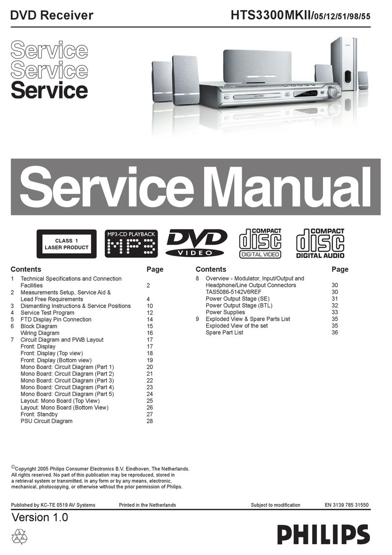
  9. Philips MX3660D/21H User manual

Philips MX3660D/21H User manual

DVD
Receiver
|
MX3660Dre1Wws037
SOnvice
Serwics
Service
For
repair
information
on
the
Subwoofer,
please
refer
to
Service
Manual
DVD
COMPACT
SW3660/17
(12NC:
3139
785
30380)
&
SW3660/00
(12NC:
3139
785
30420).
-
aa
St
Alb
TABLE
OF
CONTENTS
Ares
Location
of
PC
Boards
.u.......seesssseseesseentsseeserseeeteenees
Bea
a
Versions
Variation
&
Package
........sscssecesesseetseees
Specifications
........srsecsccecsssccssscersecsssecsscesseresestecsarsnees
Measurement
Setup
......scescecsssssesseersrenssssseeteeneresesers
Service
AidS
........:escesssceseeesseerseens
Wi
teadexsnsth
Seckenvachenricins
~
ESD
&
Safety
Instruction
.............:ccccsscsscseseseceeseeee
Seiting
Procedure
&
Repair
Instructions
Disassembly
Instructions
&
Service
positions
..............
3
Block
&
Wiring
Diagram...
essssssssseseesssseesseseneeeseetees
4
Key
/
LED
Board.
cccseicscesncsssississsevessescenvecresscenneenseurssvens
5
Power
Board
......ccscssssssesssssersensseecesescessanssesenesuasseenseesens
6
DVD.
Module:
2.
scccaciecscccscccesahsieecacicdeatinatedieitesaacSiaceceucbabes
7
Main
Board
(Include
Headphone
Board)
..........es.se0
8
RGBIBOAIG
cciccsstccssciscsscwscecssesedisbensanteicecicivaepartbweches
Setaye
9
Mechanical
Exploded
View
&
Parts
List...
10°)
CLASS
1
©
Copyright
2003
Philips
Consumer
Electronics
B.V.
Eindhoven,
The
Netherlands
LASER
PRODUCT
All
rights
reserved.
No
part
of
this
publication
may
be
reproduced,
stored
in
a
retrieval
system
or
transmitted,
in
any
form
or
by
any
means,
electronic,
mechanical,
photocopying,
or
otherwise
without
the
prior
permission
of
Philips.
Published
by
BB-ET0326
Service
Audio
Printed
in
The
Netherlands
Subject
to
modification
3139
785
30410
PHILIPS
Version
2.0
oD
LOCATION
OF
PC
BOARDS
e
Lg
2
YEE
»
A
te
VERSION
VARIATION:
MX3660D
MX3660D
MX3660D
Type/Versions
Features
&
Board
in
used
|
i
ee
a
SPECIFICATIONS
AMPLIFIER
SECTION
Power
Output
~
Stereo
Mode
(DIN)........ssssssccessesereeseeeseeeeeseennentes
2x50W
sts
seendedelsau
ad
sae
seenscssatamss
iadenete
beceste
as
caansteategeceeesateaps
2x40W
FTC
-
Surround
mode
(1
KHZ)........:esseeeeeees
50
W
RMS/channel
Total
Harmonic
Distortion............
10
%
at
rated
power
(1
kHz)
Frequency
ReSponse
........2ssceseeeees
180
Hz-14
kHz/+1
dB
Signal-to-Noise
Ratio.........sccscceseeeeseereneeeeveese
>
65dB(CCIR)
Input
Sensitivity.
.........-scsccceseecsenereeesertssnsensseeseeneoeseees
400
mV
DVD
SECTION
LASEr
TYPC........eseseesecnsessensesseeneseeseasneeseesseesees
Semiconductor
Disc
Diamete.........scc:ssserserressecssresecesseseeeseseessenseees
12cm/8cem
Video
DOCOGING.........sscccesseteseesssesrersterereeesennerenens
MPEG-2
AUdIO
DAG......cccccsscccnccssssssnsscssccornesrsceascenanecnneenseassessneas
10
Bits
Signal
SyStem........-.scsssssssensceseeessessensseneeeneensananes
PAL/NTSC
Video
FOrmal.........ccscccsessssrsessesseessessenseeseneseneesnenseneen
4:3/16.9
Vid@O
S
/
Niu.
cesscscescesnerercensessenscsseseeeseneetnes
56
dB
(minimum)
Composite
Video
Oput..........secscseeseereneetees
1.0V
p-p,
75Q
S-VideO
OUTDUL.........eeeceeeeseseseeeseseeeseesesennrees
Y-1.0V
p-p,
75Q
pcseuddsuea
ctl
dstasata
supa
savage
asectasseacasencesseadsesectete
C-0.286Vp-p,
75Q
AUdIO
DAC...
ceesesscecsseneneeesenees
Direct
Digital
Amplification
Frequency
RESpOnse.........cseseecereees
4.Hz-20
kHz
(44.1kHz)
PB
Ss
tesdes
ch
Uceisavapyssddsbensstenes
puesicuettessesns?
4Hz-22
kHz
(48
kHz)
sucdtsteadecpavetbanded
cedeatastdvsteevecsetosdsscceeeseseten
4.
Hz-44
kHz
(96
kHz)
Digital
OUtpUut........-..seeeesseneneeseeeeee
SPDIF
Coaxial
&
Optical
TUNER
SECTION
Tuning
Range.........
FM
87.5
-108
MHz
(100
kHz
steps)
(/37)
Tuning
Range....FM
87.5
-108
MHz
(50
kHz
steps)
(/21H,/30)
Ce
pbilstaeaOancduedestdesussenns’s
AM530
-
1710kHz
(10
kHz
steps)
(/37)
Sadaivendeney
Jeipestsiess
MW
581
-
1602
kHz
(9
kHz
steps)
(/21H,/30)
26
dB
Quieting
Sensitivity........-.scsssecsecerecereeees
FM
20
dB
26
dB
Quieting
Sensitivity...........csesceeeeeees
AM
5000
uV/m
Image
Rejection
Ratio..........-cescssssssrsesenseneres
FM
25
dB
sas
Godbcaddesunuachcceduedenseanseitacerceecesaesiiatetageasecenedtede
AM
28
cB
(/37)
dep
lsdcanabbgyesstas
sued
sescnduceeedeastibtévaswdancssnss
MW
28dB
(/21H,/30)
IF
Rejection
Ratio..........sssscerseseeserssensestnenensenes
FM
60
dB
Saget
aebusbesahasncd
sled
rads
aanutudese
casasnateetvsereesessuaeend
AM
24
dB
(/37)
soighaaddacacesuedudeckUeaesuined
stvacveninca
snsaseacesventen
MW
24dB
(/21H,30)
Signal-to-Noise
Ratio........csseccseseresseeersenesseseees
FM55¢cB
sdiseuadovaseitvendcesehcessGeshcanfansdcatedstnoncesntawdaacean
sate
AM
35
dB
(/37)
sages
anandenessedeaesensausaatoleccccbancosatessesbeetuass
MW
35
dB
(/21H,/30)
AM
Suppression
Rattio.........ssscsccsnsscesrenseeeenseneeees
FM
30
dB
Harmonic
Distortion..........--sscsssesesssesesecnenseseseers
FM
Mono
3%
scuthdasuweavevestetustedsectesdbavesuccsesteansudeeuuentese
duenauntoceses
FM
Stereo
3%
i
Sbadh
vasa
saat
hasten
a
bebsluise
Coad
couseasentedestnededucceeets
vente
AM
5%
(/37)
sas
iau
de
sdaveeses
es
vandoumbusetcssg.
esebecaviurassssdncnen’
MW
5%
(/21H,/30)
Frequency
RESponse.........s.srsee
FM
180
Hz-10kHz/+6
dB
Stereo
Separation...........sssssscseeseeseesesrerseers
FM
26
dB(1
kHz)
Stereo
thresShold.........csccesccccersscussssssssseceesereneeees
FM
23.5
dB
MISCELLANEOUS
Power
Supply
Rating..........-sssssesssceereneeees
120V/60
Hz
(/37)
Power
Supply
Rating.............
220-240
/50-60
Hz
(/21H,/30)
Power
ConSumption.........sssscsecssssersssesseeteeeseneseersenes
160W
Dimensions
(w
x
h
X
).......ece
435
mm
x
81
mm
x
360mm
wasted
eadddseutrecUavbuctastacnuaacdecacece
qrossssesseereseee
t
7-1X3.1X
14.2
(inch)
WGIGHL..........cseccereeessssrsscnsseseseesserereerseerseruecsneensnteeneenees
5.1kg
dvd
de
aceec
wae
drcb
eG
beticesceateseTeitotan
ds
Sebednessacaavecvoites
11,2
pounds
1-3
IR
REMOTE
CONTROL
Effective
[email protected]
>8
Meter
Number
Of
KeyS.........ccceseccecsssesesecesesteseeonensncensnensenseassanas
45
Battery
(1.5V).....::ecssssssssesessseenseenenresecerseeesasanenessees
AAX
2
SPEAKERS
Front
Speakers
/
Surround
speaker
SYSTOM....ececesecsssenesssscssecsecceessenecsneneenenessnscnaees
2-way
shielded
IMP
OCANCE....sssesececssersssssssnnsnosssnsnussssnssssseenteenenereceeceeossssensssneeanenseeeeenents
8Q
Speaker
Crivers.........ssccsccesesereerscees
3"
full
range,
1"
piezo
Dimensions
(WXNXd).......sseeceeeee
96mmx
155mmx95mm
essa
eked
Aiuto,
b
Sena
eautanaedeaseasateas
ceasensesate
3.78x
6.
10x
3.74(inch)
WEIGNIL............ecccecscsceesssesseeseeserarseeneessesesauneten
0.45
Kg/each
sia
Jawatnvideuadasudcatieadcaasangiesatecsscesuscesedececeatencees
0.99
pounds/each
Center
Speaker
SYStOM....ccssccceesesessssenseessneeneseseeeestenees
5
multidirectional
driver
Impedance...........++
satieanstt
discos
ta
tesuautcvasedtersicentncnanoseanaess
8Q
Speaker
rivers......ssescsceceeenceeres
4x
2"
woofer,
13/4
"tweeter
Dimensions
(WX
NX
Q)........0eeeee
435
mmx
72mm
x
63.5
mm
midasladucsherluces
adeideeesuclececeees
stestieds
17.13x
2.83x
2.5
(inch)
(/37)
VV
ISH
aoanazsiseskcesccaatncshcsasartndantaeuocbeas
nacas
deapeasnaeatons
we
1.32kg
hats
Ma
stwaschaitalettoctbusdsessasuectecunsccesessesousea
2.90
pounds
(/37)
i
}
H
1-4
ee
wee ewe
ee
ee
eee
we
eee
ew
EE
ee
ee
ed
|
AC
MILLIVOL
TME
TER
AUTO
DISTORTION
METER
LOAD
4
OHM
AC
MILLIVOL
TME
TER
AUTO
DISTORTION
METER
LOAD
4
OHM
OSCILLOSCOPE
SIGNAL
GENERATORAC
AM-FM
STEREO
SIGNAL
GENERATOR
SIGNAL
GENERATORAC
AM-FM
STEREO
SIGNAL
GENERATOR
INPUT
OUTPUT
INPUT
OUTPUT
Q)
G
©
e
AM
SECTION
FM
SECTION
[ee
ee
ee
|
r
i
1
i
i
i
I
i
1
1
i
i
i
f
I
1
'
I
i}
!
i]
i]
1
4
i]
i]
i]
i]
4
i
!
!
i
'
t
1
t
a
.
ee
|
ee
ee
eee
ee
eel
ee
AC
MILLIVOL
TME
TER
AUTO
DISTORTION
METER
LOAD
4
OHM
AC
MILLIVOL
TME
TER
AUTO
DISTORTION
METER
LOAD
4
OHM
OSCIL
LOSCOPE
OSCIL
LOSCOPE
SIGNAL
GENERATORAC
DVD
TEST
DISC
DOLBY
TEST
METER
INPUT
OUTPUT)
DISC
SECTION
AUX
SECTION
ree
eee
eee
ee
ee
eee
ee
eee
EG
messes
mmm
mmm
meee
——see
em
ee
ee
eee
ee
ee
ee
ee
ee
ee
e
i
1
i
{
Li
4
i]
i]
i]
1
i]
i]
'
Lj
4
i]
i
i]
4
i]
!
t
'
'
i]
i]
i
1
I
i
i
i
i]
i]
4
t
t
.
1-5
SERVICE
AIDS
Service
Tools:
ESD
Equipment:
Universal
Torx
driver
holder
..........--:..:::ssssecseseeseee
4822
395
91019
Anti-static
table
mat
-
large
1200x650x1.25mm
...4822
466
10953
Torx
bit
T10
150MM
........
ce
ceeeesseeseessecetenseneeeees
4822
395
50456
anti-static
table
mat
-
small
600x650x1.25mm
.....4822
466
10958
Torx
driver
set
T6-T20
.........
ce
ssecsessessseeseesnasensees
4822
395
50145
Antti-static
Wristband
0...
ccccccecssssseresseeseesecnneeaanee
4822
395
10223
Torx
driver
T10
extended
......cccscssesecsserserstseres
4822
395
50423
Connectorbox
(1MQ)
.........+.
iissueceslusesasansueseataives
4822
395
11307
Extension
cable
(to
connect
wristband
to
conn.box)
..........
4822
320
11305
Connecting
cable
;
Compact
Disc:
(to
connect
table
mat
to
conn.box)
...........
4822
320
11306
SBC426/426A
Test
disc
5
+
5A
....essscecsssenseeeees
4822
397
30096
Earth cable
(to
Connect
product
to.
mat
or
box)
--4822
320
11308
§$BC442
Audio
Burn-in
test
disc
1KHZ
..............04
4822
397
30155
Compiete
kit
ESD3
SBC429
Audio
Signals
disc
...........ccssecesseneeeees
4822
397
30184
(combining
all
above
products)
..............
4822
320
10671
Dolby
Pro-logic
Test
DiSC
...........sscessescescssresseesnes
4822
395
10216
Wristband
testes
0.0.0...
scssscsccseseestseensescteeseenes
4822
344
13999
HANDLING
CHIP
COMPONENTS
GENERAL
DISMOUNTING
MOUNTING
VACUUM
PISTON
6g
A
PAIR
OF
TWEEZERS
385
10082
SOLDERING
IRON
oF
WELLER
solder
tip
PT-H7
SOLDERI
{RON
SOLDER
WICK
4822
321
40042
A
TWEEZERS
SOLDERING
TIME
SOLDER
Se
APR
©,
<3
sec/side
[email protected]
PRESSURE
SOLDERING
IRON
HEATING
PRECAUTIONS
CORRECT
ee
Si
SERVICE
PACKAGE
WARNING
All
ICs
and
many
other
semi-conductors
are
susceptible
to
electrostatic
discharges
(ESD).
Careless
handling
during
repair
can
reduce
life
drastically.
When
repairing,
make
sure
that
you
are
connected
with
the
same
potential
as
the
mass
of
the
set
via
a
wrist
wrap
with
resistance.
Keep
components
and
tools
also
at
this
potential.
CF)
ATTENTION
Tous
les
IC
et
beaucoup
d'autres
semi-conducteurs
sont
sensibles
aux
décharges
statiques
(ESD).
Leur
longévité
pourrait
étre
considérablement
écourtée
par
le
fait
qu’aucune
précaution
n’est
prise
&
leur
manipulation.
Lors
de
réparations,
s’assurer
de
bien
&tre
relié
au
méme
potentie!
que
la
masse
de
l’appareil
et
enfiler
le
bracelet
serti
d’une
résistance
de
sécurité.
Veiller
&
ce
que
les
composants
ainsi
que
les
outils
que
!’on
utilise
soient
également
a
ce
potentiel.
(D>
warnune
Alle
[Cs
und
viele
andere
Halbleiter
sind
empfindlich
gegeniiber
elektrostatischen
Entladungen
(ESD).
Unsorgfaltige
Behandlung
im
Reparaturfall
kan
die
Lebensdauer
drastisch
reduzieren.
Veranlassen
Sie,
dass
Sie
im
Reparaturfall
Uber
ein
Pulsarmband
mit
Widerstand
verbunden
sind
mit
dem
gleichen
Potential
wie
die
Masse
des
Gerates.
Bauteile
und
Hilfsmittel
auch
auf
dieses
gleiche
Potential
halten.
CNL)
WAARSCHUWING
Alle
iC’s
en
vele
andere
halfgeleiders
zijn
gevoelig
voor
electrostatische
ontladingen
(ESD).
Onzorgvuldig
behandelen
tijdens
reparatie
kan
de
levensduur
drastisch
doen
verminderen.
Zorg
ervoor
dat
u
tijdens
reparatie
via
een
polsband
met
weerstand
verbonden
bent
met
hetzelfde
potentiaal
als
de
massa
van
het
apparaat.
Houd
componenten
en
hulpmiddelen
ook
op
ditzelfde
potentiaal.
Ci)
awerrimeNTo
Tutti
IC
e
parecchi
semi-conduttori
sono
sensibili
alle
scariche
statiche
(ESD).
La
loro
longevita
potrebbe
essere
fortemente
ridatta
in
caso
di
non
osservazione
della
pit
grande
cauzione
alla
loro
manipolazione.
Durante
!e
riparazioni
occorre
quindi
essere
collegato
allo
stesso
potenziale
che
quello
della
massa
dell’apparecchio
tramite
un
braccialetto
a
resistenza.
Assicurarsi
che
i
componenti
e
anche
gli
utensili
con
quali
si
lavora
siano
anche
a
questo
potenziale.
Safety
regulations
require
that
the
set
be
restored
to
its
original
condition
and
that
parts
which
are
identical
with
those
specified,
be
used.
Gy)
Veiligheidsbepalingen
vereisen,
dat
het
apparaat
bij
reparatie
in
zijn
oorspronkelijke
toestand
wordt
teruggebracht
en
dat
onderdelen,
identiek
aan
de
gespecificeerde,
worden
toegepast.
©
Les
normes
de
sécurité
exigent
que
l'appareil
soit
remis
a
l'état
d'origine
et
que
soient
utiliséés
les
piéces
de
rechange
identiques
a
celles
spécifiées.
@
Bei
jeder
Reparatur
sind
die
geltenden
Sicherheitsvorschriften
zu
beachten.
Der
Original
zustand
des
Gerats
darf
nicht
verandert
werden;
fir
Reparaturen
sind
Original-Ersatzteile
zu
verwenden.
©
Le
norme
di
sicurezza
esigono
che
l'apparecchio
venga
rimesso
nelle
condizioni
originali
e
che
siano
utilizzati
i
pezzi
di
ricambio
identici
a
quelli
specificati.
"After
servicing
and
before
returning
set
to
customer
perform
a
leakage
current
measurement
test
from
all
exposed
metal
parts
to
earth
ground
to
assure
no
shock
hazard
exist.
The
leakage
current
must
not
exceed
0.5mA.”
“Pour
votre
sécurité,
ces
documents
doivent
6tre
utilisés
par
des
spécia-
listes
agréés,
seuls
habilités
a
réparer
votre
appareil
en
panne”.
CLASS
1
LASER
PRODUCT
3122
418
03420
Warning
!
Invisible
laser
radiation
when
open.
Avoid
direct
exposure
to
beam.
cS)
Varning
!
Osynlig
laserstralning
nar
apparaten
ar
6ppnad
och
sparren
&r
urkopplad.
Betrakta
ej
straien.
GBD
Varoitus
!
Avatussa
laitteessa
ja
suojalukituksen
ohitettaessa
olet
alttiina
nakymattomalle
laserisateilylle.
Ala
katso
sateeseen!
@K
Advarse
!
Usynlig
laserstraling
ved
abning
nar
sikkerhedsafbrydere
er
ude
af
funktion.
Undga
udsaettelse
for
straling.
2-1
System,
Region
code,
Tuner,
etc.
setting
procedure
Hence
in
total,
reprograming
will
be
done
by
way
of
the
1)
System
Reset
remote
control.
It
should
run
as
below
:-
a)
Press
"SYSTEM"
button
on
R/C.
TV
show
"SETUP"
b)
Select
the
menu
using
the
"W"
and
"}"
button
on
R/C
c)
Go
feature
setup
page
to
do
system
reset
a)
Put
the
player
in
stop
mode.
No
disc
loaded.
b)
Press
the
following
key
on
remote
control:
2)
Region
Code
Change
After
replacement/
repair
of
the
MPEG
board,
the
customer
_setting
and
the
region
code
may
lost.
Changing
the
Region
code
will
put
the
player
back
in
the
state
which
it
has
left
the
For
MX3660D/37
(USA)
<PLAY>
<159>
<111>
<006>
<08>
PLAY
For
MX3660D/21H
(APAC)
factory.
<PLAY>
<159>
<331>
<006>
<08>
PLAY
Region
Code
{
USA
For
MX3660D/30
(AUSTRALIA)
2
EU
<PLAY>
<159>
<431>
<006>
<08>
PLAY
3
AP
4
Australia,
NZ,
Latam
5
RUSSIA,
INDIA
6
CHINA
TV
System
1
NTSC
2
PAL
3
AUTO
*
After
the
Region
Code
is
changed
it
is
necessary
to
reset
the
system
so
that
the
new
Region
Code
will
be
fully
Menu/
Audio
Subtitle
(AS)
Language
effective.
All
customer
setting
will
be
lost.
1
English
2
English
3
English
*
On
top
of
the
maximum
number
of
times
allowed
for
4
English
changing
the
region
code
is
changed
to
25.
*
When
the
counter
reach
25,
you
will
not
be
able
to
further
change
the
code
until
you
reset
the
timer
by
the
Region
Code
timer
reset
procedure
AFS
001
LX3000D/LX3500D
002
MX3600D/MX3700D/MX3800/MX3550D
003
LX3700D/LX3750W
005
MRD210
006
MX3660D
oem
derivative
08
=
region
code
=
1
digit
*
tv
system
=
1
digit
«
"as/menu
lang"
=
1
digit
"
"AFS"
=
"architechture
Feature
Set"
=
3
digits
This
field
is
used
to
define
the
architecture
/
features
sets
for
each
product.
=
"oem
derivative”
=
2
digit
This
field
is
use
to
define
the
OEM
set.
This
will
affect
the
background
display.
3)
Region code
change
timer
reset
Press
below
key
to
reset
the
timer
:
a)
In
DISC
source,
stop
mode
and
no
disc
in
tray.
b)
Press
R/C
"Play
-159-PLAY"
to
reset
timer
to
25
4)
Tuner
area
change
a)
Press
the
"OPEN/CLOSE"
button
to
openthe
set's
door
b)
Press
"1"
"5"
"9"
button
by
using
R/C.
c)
TV
Show
"TUNER
AREA
ADJUST"
d)
Select
the
tuner
area
you
wantby
using
the
"W"
and
"®"
button
on
R/C,
then
press
"OK"
to
confirm.
TV
show
"
TUNER
AREA
CHANGED"
If
you
didn't
press
it
in
five
seconds,
the
system
will
remain
original
status.
~
AREA
|BAND
|
FREQUENCY
(Hz)
|
STEP(Hz)
lem
|87.5M
108M
100K
10K
ol
te)
Oo
eh
_~
“I
oO
Oo
A
EUROPE
Fr
ora
oa
al
jraram
=
Lem
_[e7.sm_|
108m
__|
50k
JausTRALiA
[em
_|e7.sm_|
108m
|
sok
_|
nz__[am
|
sor
[isoaxe
[ox
Note
:-
(a)
Please
refer
to
the
above
different
tuner
area.
5.
Video
Out
Change
a)
Press
"SYSTEM"
on
R/C
button
b)
Select
the
menu
using
the
"W"
and
'B"
button
on
R/C
c)
Go
picture
setup
page
select
Video
out
item.
6.
Password
Change
a)
Press
"SYSTEM"
on
R/C
button
b)
Select
the
menu
using
the
"W"
and
'B"
button
on
R/C
c)
Go
feature
setup
page
select
"PASSWORD".
TV
show
“ENTER
CODE".
Press
4
times
of
"STOP"
button
on
R/C.
d)
Select
"PARENTAL"
"8
ADULT"
on
TV.
e)
Enter
PASSWORD
to
"1234"
*
"1234"
is
a
default
password
supplied.
7.
Checking
on
the
Software
version
a)
Open
the
CD
door.
b)
Press
"123"
and
"OK"
on
the
remote
control.
c)
TV
will
show
the
version
on
screen.
8.
Upgrading
new
software
a)
Open
the
CD-door,
then
insert
the
CD-R
program
disc.
b)
Close
the
CD-door.
c)
TV
will
show:-
*
"disc
loading”
""bank30.rom"
-
"writing"
about
6
seconds.
*"Done"
*
The
latest
upgraded
is
in
version
VER0622.
REPAIR
INSTRUCTION
MAIN
UNIT
REPAIR
CHART
CAS
“Ce.
°1C0))
ip
Ge
(Di
~Ge).
GD
Gi)
Gy
OO
All
Function
VFD
Display
DVD
Power
Supply
Audio
Output
AUX/TV
in
°
No
Working
No
Show
No
Sound
No
Working
No
Sound
No
Sound
And
Key
Function
All
Function
No
Working
No
TUNER
Ear
Head
Phone
Audio
Line
Digital
Line
Subwoofer
Line
No
Sound
No
Sound
No
Output
No
Output
No
Sound
VFD
Display
No
Show
And
Key
Function
Check
All
System
RE-Insert
and
fix
All
cable
is
loose
or
bad
INT
Check
Control
PCB
RB201
Cable
loose
or
bad
INT
Yes
Yes
RE-insert
and
fix
th
bt
the
cable
e
cable
Check
Control
PCB
RB201
Pin5=5V
Check
Back
Power
PCB
Panel
standby
LED
show
No
Check
Back
power
PCB
Bad
i
Power
Supply
Circuit
Working
or
Not
F901
Bad
Cause
Damage
Change
F901)
Check
Main
PCB
CN202
CN904
Cabke
loose
or
bad
INT
Check
+5V
Power
Yes
Re-Insert
and
fix
the
cable
Repair
Between
Check
CN203
CN906
No
Supply
circuit
RB906
TO
CN906
and
CN203
Circuit
12V
if
Right
Check
Test
CN202
Pin2/cs
checkC
RB201
cable
loose
or
bad
WNT
Check
Test
CN202
Pin5=5V
Pin6=—24V
Pin7,8=AC2V
Check
Repair
Control
PCB
1C981
Standby
circuit
Reinsert
and
fix
check
1C1003
the
cable
Check
Repair
Check
IC9001
PINS=5V
1¢1002
No
Switch
Power
Supply
Circuit(see
B)
Check
IC9003
PIN=3.3V
Correct
Check
1C1003
Pin24(reset)
Pin49(ose
frequency
27MHZ)
Pin102(114MHZ)
Check
All
Voltage
3.3V
Repair
Main
PCB
Between
Check
VFD
Controf
PCB
Section
Bad
Cause
Damage
and
5Vgive
circuit
1C1003
to
IC1007
circuit
REPAIR
INSTRUCTION
CD)
Power
Supply
No
Working
All
Voltage
No
Output
Yes
Check
F901
Bad
Cause
Damage
Check
RL901
No
Working
or
Not
Y
Check
T903
pin3
approx
if
+280v
Voltage
No
es
No
Check
BR901
and
RT901
2-3
Chage
JK182
RB1006
CN1006
+30
V_
Voltage
No
Output
+6
V_
Voltage
No
Output
+12
V_
Voltage
No
Output
-24
V_
Voltage
No
Output
Check
RL901
and
its
conn
circuti
eC!
IU5,
JUN,
1C904,SN901,D902,D906,
D907,
D905
and
their
_|
conjoint
part
DVD
No
sound
DVD
DvD
No
Reading
NO
Video
7
+
|NO
Check
CN801,CN802,CN803
No
_|
Re-insert
and
fix
To
DVD
loader
cable
loose
"
the
cable
or
bad
INT
|
yes
Check
Q9005
"e"=8.8v
Q9006
“e"=2.5v
1C9002
Pin3=3.3v
Check
JK182
OK.
or.
BAD
=e
OK
Check
RB1006
CN1006
OK
or
BAD
Check
Q9005,IC9004!
1c9004
Q9006
OK
;
Check
SPIN~M
SLED-M
Check
IC1003
and
its
around
part
Check
1C801
and
its!
no
around
part
check
IC802
Pin5,Piné
Check
IC803
and
|-NO
Pin7,Pin8
its
around
part
Check
D905
and
.
ony
its
conjoint
part
Check
D906
and
its
conjoint
part
Check
D907
and
its
conjoint
part
Check
D908
and
its
conjoint
part
Check
CN904
and
its
conjoint
part
-Icheck
Repair
in
3.3v
2.5v
|_No
net
its
conjoint
part
Check
IC1003
and
its
conjoint
part
Check
IC801
PIN1
Pin46,Pin47,Pin39,Pin40
Check
IC802,IC804
and
around
part
DVD
Audio
NO
sound
Check
CN905
RB905|
-
+30V
Check
1C801
Pin4,pin5
NO
pin6,pin7,pin13,pin14
Check
IC801
around
part
Check
!C801
NO
Pin39
Pin40
YES
Check
IC803
NO
Pini8,Pin21
YES
ES
Check
!C803
and
its
around
part
Audio
Output
L/R
channel
No
Sound
No
Sound
Ye
s
Check
1C501,IC502,1C503
RS/Center
channel
,
Pin4,7,12,15
Voltage=30V
No
Sound
S
channel
No
Sound
Repair
Between
IC1003
1C501,1IC502,IC503
to
and
1C401
circuit
Check
10401
their
Voltage
Correct
is
3.3v
2.5v
Check
Between
1C¢401
to
IC1003
Circuit
Check
iC801
And
around
part
Check
IC802
No
{Check
IC802
around
Pin30,Pin31
part
Check
between
IC802
IC803_
Circui
Repair
Between
1C401
to
JK501
and
IC501
Repair
Between
10401
to
JK501
and
1C502
circuit
Repair
Between
|C401
to
JK501
and
IC503
circuit
REPAIR
INSTRUCTION
No
FM
function
Check
FM
IF
Output
Q101,Q102
Yes
Check
FM
IF
Output
Q101,0102
Yes
Check
T105
Check
@103,0104
soon
REpair
FM
IF
section:
Between
EF001
to
Q101/Q102
circuit
Aux/TV
in
No
Sound
Check
Q9003"C"=+12v
09004"C"=+5v
Q9002
Circuit
OK
Check
IC1006
and
around
Part
Check
AM
IF
(T102/CF103)
Check
1C152
Data
From
RB101
Pin3/CE,
Pin4/DI,
Pin5/CL,
Pin6/DO
Check
JK304
loose
or
bad
INT
Check
tuner
VT
From
C164
|
usin
LOW
Frequency=1.5-2.0v
High
Frequency=8.0-9.0v
VT
No
Change
Check
{C101
audio
output
IC101
Pini6
to
RB101
Pini3(R-CH)
IC101
Pint7
to
RB101
Pint5(L-CH)
REpair
Emdec
section:
Between
Shack
Spel
pinged
78
C101
Pin21
to
Pin22
circuit
Pin7=-7v
affirm
Correct
Check
+7v
and
—7v
give
Circuit
Check
IC152
OSC
input
Pin13—--AM
input
Pinl4—-FM
input
Check
Repair
Between
RB101
to
main
pcb
1C104
and
IC104
Circuit
Chect
main
PCB
of
Tuner
input
Circuit
(Between
IC400
Pin2
and
Pini5
to
Tuner
PCB
circuit)
Check
Repair
Between
I1C3001
to
JK304
and
103001
Circuit
A:
Repair
AM
osc
section
(T003)
or
(Between
IC101
Pin30
to
1C152
Pin13
circuit)
B:
Repair
FM
ose
section
(Between
EF001
Pin8
to
IC152
Pint4
circuit)
VT
section
Circuit
Check
IC152_
or
Check
Repair
IC1010
and
its
around
parts
Ear
Head
Phone
No
Sound
subwoofer
Line
No
Output
Audio
Line
No
Output
Check
IC401
pin
(33
34)
At
DVD.
mode
Check
Q2011
"c"
=+5v
Check
Between
RB3001
to
Check
CN3001
Cable
loose
or
INT
Check
!C1010
To
IC305
IC306
e307
Circuit
RE-insert
and
fix
the
cable
+5v
Supply
Circuit
Check
1C4001
pin-1
Check
Repair
1C4001
Circuit
Check
Between
JK2003
to
1C1003
Pin41
Circuit
Check
Between
1C305,1C306,IC307
To
1¢304
Circuit
Check
Between
C1008
TO
C303
and
IC301
Circuit
No
Check
IC1008
and
its
around
Check
JK2004—-B
Check
mack
10301
Circuit
obee
0303,0304
circuit
IC1003
Circuit
DISASSEMBLY
INSTRUCTIONS
Dismantling
of
the
DVD
Module
Dismantling
of
the
Front
Panel
Assembly
1)
Loosen
4
screws
"A"
to
remove
the
DVD
Module
as
shown
in
figure
4.
ne
1)
Open
the
DVD
Tray
by
using
the
Open/Close
Button
2)
Return
the
set
to
its
upright
position
and
remove
the
Tray
while
the
Setis
ON
and
disconnect
the
mains
supply
after
Cover
as
shown
in
Figure
3
and
close
the
tray
manually
removing
the
Tray
Cover.
by
pushing
it
back
in.
Note:
Ifthis
is
notpossible,
the
DVD
Tray
has
to be
open
3)
Loosen
9
screws
and
remove
the
Top
Cover
by
lifting
the
manually.
rear
portion
upwards
before
sliding
it
out
towards
the
rear.
-
5
screws
on
the
back
Take
a
mini
screw
driver
about
2mm
diameter
and
make
-
2screws
each
on
the
left
&
right
side
a
marking
24mm
from
the
tip
as
shown
in
figure
2.
place
the
set
on
its
side,
insert
the
mini
screw
driver
till
the
4)
Loosen
7
screws
&
lift
up
the
top
edge
of
Front
Panel
marking
and
slide
it
towards
the
right
as
shown
in
figure
assembly
to
free
some
catches
before
sliding
it
out
1
until
the
Tray
moves
out
of
the
Front
Panel.
towards
the
front.
-
4Ascrews
on
the
bottom
.
-
1
screw
"E"
on
the
inside
as
indicated
in
Figure
8.
-
1
screw
each
on
the
left
&
right
side
Figure
4
Dismantling
of
the
Power
Board
1)
Loosen
2
screws
"B"
on
the
bottom
cover
as
shown
in
figure
5.
3)
Loosen
4
screws
"C"
at
the
top
of
the
Power
Board
as
shown
in
figure
6
Figure
1
Figure
2
Figure
3
Figure
5
Figure
6
3-2
3-2
Dismantling
of
the
Tuner
PCB
SERVICE
POSITIONS
1)
Loosen
8
screw
"
D
"
at
the
back
panel
as
shown
in
figure
Service
position
A
7.
2)
Loosen
6
screw
"
F
"on
the
top
of
main
board
as
shown
in
figure
8.
8
tote
Sahat,
.
Figure.7
Note:
In
some
service
positions
the
components
or
copper
patterns
of
one
board
may
risk
touching
its
neighbouring
pc
boards
or
metallic
parts.
To
prevent
such
short-circuit
use
a
piece
of
hard
paper
or
other
insulating
material
between
them.
Service
position
B
me
Figure
8
R.G.B
Jack
use
for
MX3660D/21H
MX3660D/30
MX3660D/37
Figure
9
BLOCK
DIAGRAM
SMPS
TOP249Y
BACKUP
POWER
SUPPLY
LOADER
@)
MOTOR
DRIVER
LA6560
2
2
a
>
<
4-1
TUNER
LA1387
PLL
LC72131
4.5MHz
RDS
BUI923
4.332MHz
LC78663W
116.
954
4Miiz
Fee
ae
X
il
eee
ee
EXTENSION
PORT
SWITCH
4052
'2
7MHz!
iE
SR
74HC374
X
3
4.
OOOMHz
'
[
ic98i
U-CON
h——~
D
=
Pry
3
|
so
|
D/
at
Ey
VOLUME
CONTROL
He
were
PT2259
ES6018
CPU
MPEG
DECODER
8M
FLASH
RAM
J
sear
VIDEO
FILTER
DDX8000
VOLUME
&EQ
CONTROL
EEPROM
=
a)
©)
POWER
DRIVER
STASO5
POWER
DRIVER
STASO5
POWER
DRIVER
|
STA505
Ww
mm
z=
©
On
am
LINE
OUT
©)
R
AMP
TDA2622
EARPHONE
SUB
lin
out
4-2
WIRING
DIAGRAM
=
Wr
er
JK181
=
2
—<—
ee
eee"
Soe
R.G.B
PCB
=
©
LVA102040-0402
;
ra
Oo
fATEICID)
(
LePo202c001
e
Cit}
.cpi02020-0002
=
@
N L
CN902
aa
B
.
2
a)
a:
2
S&S
o
h
aon
eve
=
+12
a
m
eS
ie
a
on
oO
ono
=
AC?!
“Oo
s
co
a
I
oO
0
90684
YY
[apa
06H
pesseees
ZO0IND
E
MAIN
PCB
ieee
$0gNd
B
LOAEHS
RG-W
108
7
10),
O
i]
ae
=
EA
=
Bg
a
~m
&s
=
°
3
2
aad
i
s
>
gar
2
s
2
Saat
S
8B
3
a
posse
seeceesees|:
©
Siena
=
8s
-
(ory
I
FO
|
2
(eoas
LVU0217C011
WOILIZONAT
RBI
SOSOSSSSESSSOSOESE
5-1
5-1
FTD
DISPLAY
PIN
ASSIGNMENT
4G 5G
6G
7G
8G
9G
10G
11G
KEY
/
LED
BOARD
julie
iN
(4G-11G)
Sie
[26
|
36
[46 [sa
|
0c
|
74
116
Pi
|Procrartapom|
3@
|
a
|
a |
a
|
@
[a
|
a
|
a
|
a
|
P|
Seon
rue]
®
|b
|
6
|»
|»
|»
|»
|»
|
®
|
P3
ee
mee
2
ma
Wa
er
VS
dO
|
Ps
{|
JN
&
k
k
FTD
Display
Pin
Assignment
..........sssssssssssesereeeeeeeeeeetens
5-1
ie
ee
ee
om
:
:
Ea
an
a
Da
pin
Contec
Nae
cake
ecdnta
ea
miactseeae
enacts
1
ae
a
ee,”
ee
Circuit
Diagranacmests
a
panusiaieasaeenteaest
5-2
reat
|
PN
em
te
tem
teow
tf
PCB
Layout
Top
ViOW
.......sssssecssssessesssreneessesessetsenseenenes
5-3
reat
mif{~tm~teleleleleletle
tle
|
PCB
Layout
Bottom
View
.......ccscssessesenssseseenseseenenes
5-3
PPO.
ee
ee
Pe,
ee
es
Electrical
Parts
List
.........--:scssssssessseenssssesensesseersnentanes
5-4
P11
ee
ee
ee
ee
ee
ee
ie
oe
Sn
oe
Pea
PHS
|
ep
a
eee
8,
|
se
eet
Oe
ee
De
a
ee
a
a
ee
ee
ie
Se
ee
Pies
a
ee
en
eee
PIN
CONNECTION
24/3)415
7
TTIT71T
17
71111])111]
1/2]
272]
2]
2/2]
2]
21/2]
2/3]
3]
3/3)
3/3
olif2/3i4|5iel7]/s]o/ol1j2t3]4i5i6]
7] 8]
9,0]
1p
2;34
415
cowecnon
[Te
[oLatalelallelalelalelalclolsllalslclalrlelaldmrardidralidelals
ij2
G|
GIG
G]
GIG}
GLGLGIGIGLC{
Cli121314i5
7
10)
11]121]
13)
14]
15116)
242
##
Note
##
1.Fn:
Filament
pin
2.nG
:
Grid
pin
3.Pn:
Anode
pin
4.NP
:
No
Pin
5.
NC
:
No
Connection
pin
CIRCUIT
DIAGRAM
A
B
Cc
D
L
eee
Ce
C201
100u/10
203
100u/35
R281
100K
TA203
PLAY/PAUSE
Je.
220
|
C295
=
102
Z0201
5V1
R225
C991
pee
|
poe
NO
w
6CHDISCRETEINPUT
RDS
PTY
CT
Sleep
‘Wake
Up
Memory
Stereo
Mono
DP251
G7
_Y_MBoe1
A.
Wrrotogic
Msstereo
nor
Phan
wide
x-Bass
c)
Sggaeeae
|
5-2
eeeeewenenas
(i
Hh)
TA212
up
VOL
C214
°°27P
R223
10K
R247
10K
ro
Luscnnncnnncscwneconensnasssnanesacesnsanasssnessesssssosssssansssassoanannsnennannsee
|
Lu
wennencssconnscenennsonscer
C201
C202
C203
C204
C205
C207
C208
C209
C212
C213
C214
C215
C216
C295
C991
C992
C993
C994
D201
D202
D203
D204
D985
DP251
iC251
1C981
LD201
Q202
Q203
Q204
R201
R202
R203
~
R204
R205
R206
R213
R214
R216
R223
R224
R227
R228
R229
R230
R231
R232
R234
R236
R238
R239
R240
R241
Al
Al
Ai
C3
C3
Bi
Bi
Bi
D3
D3
A4
A4
C3
D3
D2
D1
D1
D1
C2
C2
C3
B4
D2
B2
D2
C4
C2
C2
C3
Al
Al
Al
B1
Bi
Bi
Al
C3
A4
A4
C3
Bi
Bi
B1
C1
B4
C2
C2
D1
D1
D1
Al
R242
R244
R225
R245
R246
R250
R251
R984
R987
R988
R989
R991
Reg2
R993
R994
R995
RB201
RB202
D3
B3
D3
C3
C3
C2
c2
D1
Dt
C2
D2
D2
D2
D2
D2
D2
B4
D3
RB203A
C3
RB203B
C4
RB204A
C3
RB204B
C4
SN201
TA201
TA202
TA203
TA204
TA205
TA206
TA207
TA208
TA209
TA210
TA211
TA212
XL981
ZD201
ZD202
ZD203
C3
C4
C4
C1
c2
B2
C2
C2
C2
C2
c2
B4
A4
D1
D3
C3
C3
5-3
5-3
PCB
LAYOUT
TOP
VIEW
C201
Bi
C213
AS
D203
B2
JW204B1
JW213A3
JW222
B4
JW231
A4
R203
Bi
R227
At
R240
Ai
R993.
A2
RB205A
B4
TA205
A4
ZD201
AS
C202
Al
C214
B3
D204
A4
JW205
A2
JW214A3
JW223
A4
JW232A1
R204
B3
R228
A2
R241
A2
R994
§=A2
RB205B
B4
~
TA206
B3
ZD202
A1
C203
Bi
C215
B4
D985
A2
JW206
A2
JW215B3
JW224
AS
JW233B1
R205
B3
R229
A2
R242
B4
R995
AS
RB206A
A4
TA207
B3
ZD203
A1
C204
Al
C224
B3
DP251
B2
JW207
B2
JW216B3
JW225
BS
JW234B3
R206
B3
R230
A2
R245
B2
RB201
B3
RB206B
A4
|
TA208
B4
C205
Al
C295
AS
IC251
B2
JW208
A2
JW217B3
JW226
A5
JW235
Ai
R213
Bi
R231
A2
R246
BS
RB202
BS
SN201
A1
TA209
AS
C207
A2
C991
A2
LD201
A1
JW209
A2
JW218B3
JW227
A5
JW244A1
R214
B2
R232
A4
R988
A2
RB204B
Ai
TA201
Al
TA210
BS
C208
A2
C994
A3
JW201
B1
JW210A2
JW219B3
JW228
A3
Q204
B3
R216
At
R236
A3
R989
A2
RB203B
Ai
TA202.
«Bi
TA211
A4
C209
A2
D201
B2
Jw202B1
JW211A3
JW220
B3
JW229
AS
R201
B1
R223
B3
R238
Ai
R991
A3
RB203A
A1
TA203
AS
TA212
A5
AS
D202
B2
JW203
At
JW212A3
JW221
B3
JW230
BS
R202
Bt
R224
B3
R239
Al
R992
A2
RB204A
At
TA204
AS
~
XL981
AS
C212
PCB
LAYOUT
BOTTOM
VIEW
C1
A2
C216
AS
C993
A3
Q202
A3
R225
B4
R244
B4
R249
A3
R251
A3
R987
B3
c2~=«C«#B®*EA
cog2
A3
1C251
B4
Q203
A3
R234
AS
~~
R248
AS
R250
A3
R984
A4
Soeur
ee
eee
AAR
TNA
DAN
RSS
NEEIT
ELECTRICAL
PARTS
LIST
-
KEY
/
LED
BOARD.
MISCELLANEOUS
DP251
LD201
SN201
TA201
TA202
TA203
TA204
TA205
TA206
TA207
TA208
TA209
TA210
TA2I
TA212
XL981
DIODES
D201
D202
D203
D204
D985
zD201
zD202
ZD203
9965
000
12538
9965
000
17400
9965
000
15935
9965
000
20267
9965
000
20267
9965
000
20267
9965
000
20267
9965
000
20267
9965
000
20267
9965
000
20267
9965
000
20267
9965
000
20267
9965
000
20267
9965
000
12539
9965
000
12539
9965
000
12540
4822
130
30621
4822
130
30621
4822
130
30621
4822
130
30621
4822
130
30621
4822
130
34233
4822
130
34233
4822
130
34233
VFD
DISPLAY
LED
IRT
SENSOR
RIM
B38F
TACT
SW
SK1QN00048
160GF
TACT
SW
SK1QN00048
160GF
TACT
SW
SK1QN00048
160GF
TACT
SW
SK1QN00048
160GF
TACT
SW
SK1QN00048
160GF
TACT
SW
SK1QN00048
160GF
TACT
SW
SK1QN00048
160GF
TACT
SW
SK1QN00048
160GF
TACT
SW
SK1QN00048
160GF
TACT
SW
SK1QN00048
160GF
ROTARY
ENCODER
EC16B24-204
ROTARY
ENCODER
EC16B24-204
CRYSTAL
4.00
MHZ
1N4148
1N4148
1N4148
1N4148
1N4148
BZX79-B5V
1
BZX79-B5V1
BZX79-B5V1
TRANSISTORS
&
INTEGRATED
CIRCUITS
Q202
Q203
Q204
C251
IC981
Note
:
9965
000
14175
9965
000
14175
4822
130
41198
9965
000
12550
9965
000
17447
28A733Q,P
2SA733Q,P
2SC945P
IC
PT6311(PTC)
IC
S-CPU
EM78P156ELP
Only
the
parts
mentioned
in
this
list
are
normal
service
spare
parts.
6-1
6-1
TL431
EQUIVALENT
SCHEMATIC
CAHODE
POWER
BOARD
TOP249
BLOCK
DIAGRAM
Yo
‘SHUNT
REGULATOR’
ERROR
AMPLIRIER
COMPARATOR
CURRENT
LIMIT
COMPARATOR:
TABLE
OF
CONTENTS
Internal
IC
Diagram
&
Voltage...
Ord
Circuit
Diagtam.......
as
3
POB
LAyOUt.
ccs
sssincniestencencevteactsescuexetebcrscessvatvocecavasieuserenc
OO
Electrical
Parts
List...
REDUCTION
CD
SOURCE
(S)
PANO]
tteaptsta{s{te]
Jot
tT
t
tet:
|
fF
P
tt
Pe
votage|2.e8]
0
[-os[
ofeetis4]
fT
7
fT
tT fT tT
|
|
f
fT
jf
|
tt
PINON
ee
Me
ee
Vvotage]2.4a}
ofsi1f
[TT
Tt
T
|
T
T
[
fT
ft
|
[
fT
t
ft
ft
Ce)
DRE
2
VS
OD
PR
2
Votagela77facef2sfie7]
[ [
| |
[T
|
| T
|
fT
f
fT
ft
Jt
Tt
|
PINNO]
b |
c
fel]
|
PINNO|
b
|
c
|e
|
|
Voltagd
6.68]
31.5]
7.2]
|
Voltagd-14.-4.49-14.4
|
6-2
6-2
CIRCUIT
DIAGRAM
BR901
C1
c90s
D1
C919
E2
C933
«OFA
co49
«(FA
coe6
=
D901
C1
Des09
«El
qQ903.
-E2
R903.
C1
R921
E2
R941
C3
R952—s«C«E
SNS01
D2
ZD946
D4
c901
Bi
cg909
Dt
C920
~E2
C938
E2
ce50
«FA
C967
SCE
Ds02.
C1
D910
=—«E2
Q904
«Fi
R904
D1
R922
E2
R942
C3
R953
«iB
T901
+=Bi
cs02.
C1
c9i0
«CT
C925
«—«E2
c939
E2
C951
~F1
cg6s8
C1
Dg03
C3
F901
Bi
Qs10
C3
R905
D1
R923
E2
R943.
D4
R954
=I
Tg02.—s«éB2
c903.
C1
Ceti
D2
C926
=—-F2
C940
«~F2
C952
«=F
1
cge9
~=-~@D2
D904
D3
Ic903
D2
Qgi2
C4
R906
D1
R924
E2
R945
D4
RB904
F2
T9031
c904.
«~C2
c912
D2
ce29
«EI
C941
F2
c962
C3
C970—s
F11
D905
Et
1c904
E2
Q913
D3
R907.
D2
R925
E2
R946
«C4
RB905
Fi
ZD1
E2
C905)
=
C1
C913
«D2
C930
««E
C945
«EA
cg63
«(D1
C971
—s
F2
D906
E2
L901
Fi
Ri
E2
R908
D2
R928
F2
R947
C4
RB906
=F3
ZD901
D1
c906
=
C1
C914
«C3
C931
==F2
C947
«ET
c964
D1
c972=S«E2
D907
E1
1902
F1
R901
C1
R919
E2
R931
E41
R948
«C4
RL901
C2
ZD902
D3
C907.
—«~+D1
C915
D2
C932.
«OF
1
c948
CET
c965
«E14
CN902
B2
D808
=E2
L903.
FA
R902.
C2
R920
E2
R932
FA
R951
D3
RT901
AS
ZD903
Fi
A
B
C
D
E F
6968
,
,222/400V
C964
,
,
222/400V
a.
D905
MURI620CT
c909
4222/400V
963
222/400v
|
©965
102/1KV
+950
C952
rgo1
KBua08
A\
103
1000u/50
R931
75
945
470PF
/1KV
rs
:
cess.
«907
s
SiI¢
:
102/1KV
HER204
932
+
c970
D909
1N4148
~
L902
6uH/2.5A
104
D901
BYV26D
=
R903
1M
1/2W
R905
68K
2W
6907
103/400V
en
<>
=)
S
<=
ZD901
P6KE200A
wo.
©:
C906
)
:222/pe400v
3M3
1/4W
R904
IM
1/2W
D906
1N5822
D910
1N4148
*
230V
No
Need
c940
1000u/16
904
220u/200V
R902
560K
1/2W
coos
|
222/Dc400V
D908
HER104
C938
102
1Cc903
TOP249Y
120
1/2W
[-1%
(OPEN)
10K
+,
ZD802
5V6
R949
s2%
FOR
OTHER
MODE
R923:
30K
+/-1%
F901
T3.15AL
250V
Keu808
1N4001
BR9O1
t
2204/25
2862001
C962
104
c9ot
224/250V
R901
560K.
1/2W
224/250V
Labia
nemo
bonmb
nna
mand
ana
S
aS
SE
R942
22K
Be
he
6V3
ZD946
(R946:
10K)
[>
ewe
we
ee
ee
wwe
ee
ee
momen
nae
teen
ee
eee
ee
weenen
nnn
e
nan

This manual suits for next models

2

Other Philips Receiver manuals

Philips DTR200/00 User manual

Philips

Philips DTR200/00 User manual

Philips D2999 User manual

Philips

Philips D2999 User manual

Philips LX390SA User manual

Philips

Philips LX390SA User manual

Philips HTS3107/55 User manual

Philips

Philips HTS3107/55 User manual

Philips STU 1400 User manual

Philips

Philips STU 1400 User manual

Philips Fidelio A1 User manual

Philips

Philips Fidelio A1 User manual

Philips DCR 5012 User manual

Philips

Philips DCR 5012 User manual

Philips FR-965 User manual

Philips

Philips FR-965 User manual

Philips SLV4200 User manual

Philips

Philips SLV4200 User manual

Philips Selecon PL1WDMX01 User manual

Philips

Philips Selecon PL1WDMX01 User manual

Philips MX1015D37 User manual

Philips

Philips MX1015D37 User manual

Philips DRE420SY User manual

Philips

Philips DRE420SY User manual

Philips STU 1330 User manual

Philips

Philips STU 1330 User manual

Philips AE 3650 User manual

Philips

Philips AE 3650 User manual

Philips FR 732 Assembly instructions

Philips

Philips FR 732 Assembly instructions

Philips SLV3100 User manual

Philips

Philips SLV3100 User manual

Philips MX1050D/22 User manual

Philips

Philips MX1050D/22 User manual

Philips DTR 2010 User manual

Philips

Philips DTR 2010 User manual

Philips MX1055D37 User manual

Philips

Philips MX1055D37 User manual

Philips DSR 1000 User manual

Philips

Philips DSR 1000 User manual

Philips DTR2000/00 User manual

Philips

Philips DTR2000/00 User manual

Philips PFS0001/12 User manual

Philips

Philips PFS0001/12 User manual

Philips DTR4610 User manual

Philips

Philips DTR4610 User manual

Philips DSR2000/00M User manual

Philips

Philips DSR2000/00M User manual

Popular Receiver manuals by other brands

Sennheiser EK 2012 user guide

Sennheiser

Sennheiser EK 2012 user guide

Sirius Satellite Radio Starmate ST1 user guide

Sirius Satellite Radio

Sirius Satellite Radio Starmate ST1 user guide

Underground Magnetics Mag 6 Series quick start guide

Underground Magnetics

Underground Magnetics Mag 6 Series quick start guide

Daikin iTM plus installation manual

Daikin

Daikin iTM plus installation manual

Cypress VEX-X1102R-B0C Operation manual

Cypress

Cypress VEX-X1102R-B0C Operation manual

CNC i80 user guide

CNC

CNC i80 user guide

Yamaha RX-V663 owner's manual

Yamaha

Yamaha RX-V663 owner's manual

Novra S75 instructions

Novra

Novra S75 instructions

AMG AMG5514R instruction manual

AMG

AMG AMG5514R instruction manual

Exalt EX-2.4i Lite Installation and management guide

Exalt

Exalt EX-2.4i Lite Installation and management guide

Onkyo TX-NR535 Service manual

Onkyo

Onkyo TX-NR535 Service manual

Matsui DTR1 Retuning

Matsui

Matsui DTR1 Retuning

Audioplex TCE-TKS installation manual

Audioplex

Audioplex TCE-TKS installation manual

Phonocar VM 030 instruction manual

Phonocar

Phonocar VM 030 instruction manual

Nakamichi NA1600 user manual

Nakamichi

Nakamichi NA1600 user manual

Sony XSP-N1BT Owner's record

Sony

Sony XSP-N1BT Owner's record

JVC RX-DP20VSL instructions

JVC

JVC RX-DP20VSL instructions

SMC Networks WMR-AG - annexe 1 manual

SMC Networks

SMC Networks WMR-AG - annexe 1 manual

manuals.online logo
manuals.online logoBrands
  • About & Mission
  • Contact us
  • Privacy Policy
  • Terms and Conditions

Copyright 2025 Manuals.Online. All Rights Reserved.