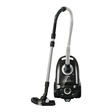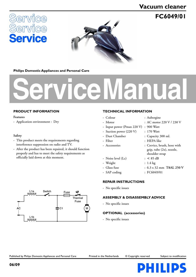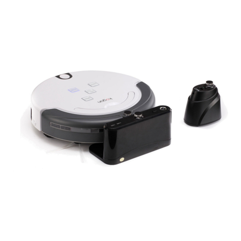
HR8572 /A /D
DISASSEMBLY- AND RE-ASSEMBLY ADVISE
- To open the appliance, first remove the 2 screws of the
control panel (item 11) then with a big screw driver
disconnect the 2 snap locks of panel and lower housing
(see drawing).
- The component configuration shown in the exploded view
may differ in case of specific versions. The components are
distinguished by means of code numbers.
- When the repair is finished, check whether all functions of
the appliance work properly.
- To (dis)assemble the appliance use TORX screw driver no
T15 (4822 395 10329), which is one of a set consisting of
T20, T15, TI0, T9, T8, T7 and T6 = 4822 395 50145.
- To connect the nozzle, the telescopic tube and the handle:
insert the narrowed section into the wider section while
turning it a little.
To disconnect: Pull while rotating. To adjust the telescopic
tube (item 74) to the required length, use the knob in the
direction of the arrow while sliding the top section of the
telescopic tube into or out of the lower section.
REPAIR INSTRUCTION
- The spare parts have been standardized as much as possible.
- Item 6, cotton dustbag, is used in those countries where
paper dustbags are not available.
- The cordwinder (item 21) is provided with a long cord-
winder spring; both long and short cords can be used in
combination with this spring.
- The cord winder spring must be tensioned to the maximum
level and then be rewound approx. 1.5 turn.
- Depending on the original cord, the spare cord must be
shortened to the length of the original cord.
- If the cord comes without AMP clamps, it can be soldered
onto the terminals.
- If the reel half spring unit is replaced, shaft Amust be
lubricated with silicone grease (A). Do not apply any
silicone grease to or spill any grease on the terminals or
conductors.
- The assembly of accessories depends on the national
version.
- Adjusting the PCB on the motor to 220V, 60Hz.
1. Make sure that the potentiometer (item 36) is set at
min. position.
2. Adjust the potentiometer on the PCB item 45, on the
motor to 220V/60Hz to allow the motor to run
smoothly.
Please note: the standard setting of the spare PCB is
230V/50Hz.
There are open-circuit voltages on all wires.
M
MOTOR
POWER
MODULE
ROTARY
POTMETER
CORD WINDER
MAIN
SWITCH
2-7

