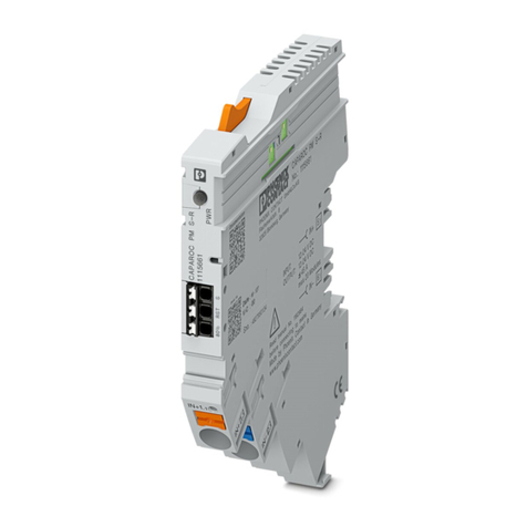
Phoenix Contact CBMC E4 24DC/1-10A IOL User manual

User manual
Multi-channel electronic device
circuit breaker with IO-Link
interface

2017-08-31
PHOENIX CONTACT GmbH & Co. KG • Flachsmarktstraße 8 • 32825 Blomberg • Germany
phoenixcontact.com
108147_en_00
Multi-channel electronic device circuit breaker with IO-Link interface
Designation Order No.
CBMC E4 24DC/1-4A+ IOL 2910410
CBMC E4 24DC/1-10A IOL 2910411
User manual
This user manual is valid for:
UM EN CBMC E4 ... IOL, revision 00

Table of contents
108147_en_00 PHOENIX CONTACT 3 / 44
Table of contents
1 For your safety ...........................................................................................................................5
1.1 Labeling of warning notes......................................................................................5
1.2 Qualification of users .............................................................................................5
2 About this document ..................................................................................................................7
2.1 Aim of this document .............................................................................................7
2.2 Hardware requirements .........................................................................................7
3 Description of the CBMC E4 24DC/1-4A+ IOL and CBMC E4 24DC/1-10A IOL ........................9
3.1 General description of the device circuit breaker ...................................................9
3.2 Possible fields of application of the device circuit breaker ...................................10
3.3 Connection and operating elements ....................................................................11
3.3.1 Channel LED button .............................................................................11
3.3.2 Diagnostics and status indicators .........................................................12
3.4 Operating modes.................................................................................................13
3.4.1 Independent operation .........................................................................13
3.4.2 IO-Link operation .................................................................................13
4 Mounting and power supply .....................................................................................................15
4.1 Mounting the device circuit breaker .....................................................................15
4.2 Power supply connection ....................................................................................16
4.3 Connecting the IO-Link connection......................................................................16
4.4 IODD file ..............................................................................................................16
5 Process data and status information ........................................................................................17
5.1 Cyclic process data .............................................................................................17
5.2 Acyclic data .........................................................................................................20
5.2.1 IO-Link specific parameters .................................................................22
5.2.2 Device-specific parameters ..................................................................23
5.3 Events..................................................................................................................28
5.4 Device access locks ............................................................................................29
5.5 Data storage (IO-Link data storage).....................................................................29
A Technical appendix...................................................................................................................31
A 1 Technical data .....................................................................................................31
A 2 Ordering data.......................................................................................................35

CBMC E4 ... IOL
4 / 44 PHOENIX CONTACT 108147_en_00
B Appendixes...............................................................................................................................37
B 1 List of figures .......................................................................................................37
B 2 List of tables ........................................................................................................39
B 3 Index....................................................................................................................41

For your safety
108147_en_00 PHOENIX CONTACT 5 / 44
1 For your safety
Read this user manual carefully and keep it for future reference.
1.1 Labeling of warning notes
1.2 Qualification of users
The use of products described in this user manual is oriented exclusively to:
– Electrically skilled persons or persons instructed by them. The users must be familiar
with the relevant safety concepts of automation technology as well as applicable stan-
dards and other regulations.
– Qualified application programmers and software engineers. The users must be familiar
with the relevant safety concepts of automation technology as well as applicable stan-
dards and other regulations.
This symbol indicates hazards that could lead to personal injury.
There are three signal words indicating the severity of a potential injury.
DANGER
Indicates a hazard with a high risk level. If this hazardous situation is not
avoided, it will result in death or serious injury.
WARNING
Indicates a hazard with a medium risk level. If this hazardous situation is not
avoided, it could result in death or serious injury.
CAUTION
Indicates a hazard with a low risk level. If this hazardous situation is not avoided,
it could result in minor or moderate injury.
This symbol together with the NOTE signal word alerts the reader to a situation
which may cause property damage or a malfunction.
Here you will find additional information or detailed sources of information.

About this document
108147_en_00 PHOENIX CONTACT 7 / 44
2 About this document
2.1 Aim of this document
This user manual helps you to start up and operate the following products:
– CBMC E4 24DC/1-4A+ IOL
– CBMC E4 24DC/1-10A IOL
2.2 Hardware requirements
Table 2-1 Hardware requirements
Hardware Description
CBMC E4 ... IOL Multi-channel electronic device circuit breaker with
IO-Link interface for protecting four consumers at
24 V DC in the event of overload and short circuit. For
order data, see Section "Ordering data" on page 35
IO-Link master For order data, see Section "Ordering data" on page 35
IO-Link connecting cable For order data, see Section "Ordering data" on page 35

Description of the CBMC E4 24DC/1-4A+ IOL and CBMC E4 24DC/1-10A IOL
108147_en_00 PHOENIX CONTACT 9 / 44
3 Description of the CBMC E4 24DC/1-4A+ IOL and
CBMC E4 24DC/1-10A IOL
3.1 General description of the device circuit breaker
The CBMC E4 ... IOL is a multi-channel device circuit breaker with the possibility of setting
the nominal current. It is used to protect downstream consumers against overload and short
circuit. Using the integrated IO-Link interface also makes possible comprehensive diagno-
sis and control of the device.
Figure 3-1 CBMC E4 ... IOL
24 V DC power terminal For the device circuit breaker, observe the correct connection cross section and the maxi-
mum feeding current with regard to the ambient temperature. A corresponding temperature
derating can be found in Section "Technical data" under "Derating" on page 34.
IO-Link connection The integrated IO-Link connection according to IO-Link standard 1.1 ensures the connec-
tion to the IO-Link master. With the help of the IO-Link protocol, it is possible to receive and
send the cyclic and acyclic data of the device circuit breaker (see Section 5 "Process data
and status information").
The CBMC Circuit Breaker Multichannel Compact CBMC E4 24DC/1-4A+ IOL and
CBMC E4 24DC/1-10A IOL are identical in appearance. They only differ with regard to a
function. In the following, the term device circuit breaker or CBMC E4 ... IOL is therefore
generally used. Any differences are indicated in the corresponding sections of the text, if
necessary.
The device circuit breaker CBMC E4 24DC/1-4A+ IOL is approved for use in NEC Class 2
circuits and adjustable to 4 A.
All the latest approvals can be found on the Internet at phoenixcontact.net/products

CBMC E4 ... IOL
10 / 44 PHOENIX CONTACT 108147_en_00
Delivery state On delivery, the product has a defined default setting. All channels are switched off and set
to 4A at the factory. The user-interface locks are all deactivated and the read only memory
of the device is used for securing the device settings. You can find more standard values of
the device circuit breaker in Section 5.2 on page 20.
3.2 Possible fields of application of the device circuit
breaker
The CBMC E4 ... IOL as
overload and short-circuit
protection
The main function of the device circuit breaker is to protect the consumers and cables con-
nected on the output side against overload and short circuit. Up to 4 load current circuits can
be secured at the device circuit breaker.
In order to be able to fully operate the CBMC E4 ... IOL, a power supply and an IO-Link mas-
ter with upstream control are required.
Figure 3-2 IO-Link with CBMC topology
11
CBMC
1
-
10 A
2
3
4
1
2
L+
L–
C/Q
1
IN+ IN– OUT+
2
2
3
4
1
2
3
4
PE
N
L
ETH 1
X21
X01 X02
PWR IN
X31
ETH 2
X22
PWR OUT
X32
ACT
LNK
ACT
LNK
UA
US
30 31
X03 X04
32 33
X05 X06
UA UA
X07 X08
UA UA
RDY BF SF
U
Out
P
Out
29.5V
24V
> 100% Boost
> 75%
> 50%
DC OK
Signal
13
14
Rem
SGnd
Out 1
Out 2
QUINT POWER
Output DC 24V 10 A
++–––
N/- L/+
Input AC 100-240V

Description of the CBMC E4 24DC/1-4A+ IOL and CBMC E4 24DC/1-10A IOL
108147_en_00 PHOENIX CONTACT 11 / 44
3.3 Connection and operating elements
Figure 3-3 CBMC E4 ... IOL operating elements
1. Channel LED button
2. Protected outputs
3. 24 V DC supply
4. IO-Link interface
5. IO-Link LED
3.3.1 Channel LED button
The channel LED button of the CBMC E4 ... IOL is a multi-functional button. The channel
state can be completely influenced with it.
CBMC
1
2
3
4
1
2
L+
C/Q
1
2
IN+ IN- OUT+
1
2
3
4
12
4
3
3
IO-Link
5
L-
Table 3-1 Channel LED button
Function Description
On / Off Actuate the button briefly (<2 seconds) to switch the channel on and off.
Programming mode – The respective channel of the programming mode is activated by actuating the channel LED
button for a longer time (>2 seconds).
This is signaled by a channel LED flashing yellow.
– Now the currently set nominal current can be read out via the flashing sequence displayed on
the LED.
– Furthermore, it is possible to enter a new nominal current by briefly actuating the LED button
repeatedly
For example, 4x actuation for 4 amps.
– Afterwards, the desired nominal current can be controlled via the LED flashing sequence.
– By actuating for a longer time (> 2 seconds) the new nominal current for the channel is taken
on.

CBMC E4 ... IOL
12 / 44 PHOENIX CONTACT 108147_en_00
3.3.2 Diagnostics and status indicators
– After 60 seconds without activity the programming mode automatically
switches off. Possible changes are discarded and the channel takes on
its previous state again.
– The programming of channels can also be done while in operation. The
channels do not need to be switched off.
– Initial programming:
After the channel has been switched on, it may occur that the channel
shuts off and the LED blinks red. Check the currents that have been set.
Designation State Color Description
Channel
LED button
On Green Channel is switched on and ready.
Yellow The flowing channel current is
>80% of the set nominal current.
Red The channel has triggered due to overload or short circuit, and is in the
5-second cooldown phase.
In the case of constant illumination for more than 5 seconds, there is a
defect in the power path of the CBMC E4 … IOL. The device has to be
replaced in the event of such an error pattern.
1-4 on Red The initial voltage is outside the prescribed range of 18 ... 30 V DC.
Flashing Yellow Channel is in manual programming mode. The currently set/entered
nominal current is output by the flashing.
Red Cooling phase after short circuit or overload release ended. Restart
possible.
Off --- Channel switched off
IO-Link LED Flashing Green IO-Link communication exists (preoperate/operate)
Off --- There is no connection to the IO-Link master.
The IO-Link LED under the terminal lock of the device is used for visual communication
confirmation. The LED flashes in the case of an active IO-Link connection with data ex-
change between master and device. If you do not get any visual feedback via the LED,
check the IO-Link connection and the IO-Link master configuration.

Description of the CBMC E4 24DC/1-4A+ IOL and CBMC E4 24DC/1-10A IOL
108147_en_00 PHOENIX CONTACT 13 / 44
3.4 Operating modes
3.4.1 Independent operation
The device can be operated without an IO-Link. For this, only the supply voltage and ground
need to be connected. The channel states and the nominal currents can be adjusted via the
buttons.
After a voltage reset, the last parameters written acyclically per IO-Link /programmed by
button are loaded from the read only memory.
If the channels should first be switched off after start-up, until they are switched by buttons,
for example, this can be configure beforehand via Index 3328dec (see Section "State of the
channels after voltage reset" on page 23).
3.4.2 IO-Link operation
For operation with IO-link, the three IO-Link conductors (L+, C/Q, L-) must be connected
with the master and the port configured in the IO-Link master. If desired, the device can also
be pre-configured without supply voltage at IN+ by means of acyclic access. The output
channels can only be physically switched on, however, when the voltage at the "IN+" con-
nection is in the range of the permitted operating voltage.
The device is automatically in IO-Link operation when it is connected to a configured master
port. An existing connection is signaled by the flashing of the green IO-Link LED (under the
"L-" connection at the terminal lock, see Figure 3-3). Parameterization is then performed by
means of acyclic and cyclic access (see Sections "Cyclic process data" on page 17 and
"Acyclic data" on page 20). If the data storage mechanism in the master is active, the check-
sums in the device and in the master are compared and the parameters exchanged corre-
spondingly.
After a voltage reset, the device circuit breaker behaves identically in IO-Link operation as
in independent operation.
For safety reasons, the device access locks retain their state even after a voltage reset
(see Section "Device access locks" on page 29). If the device should be operable without
IO-Link by means of buttons, previously activated device access locks should be deacti-
vated per IO-Link beforehand.

Mounting and power supply
108147_en_00 PHOENIX CONTACT 15 / 44
4 Mounting and power supply
4.1 Mounting the device circuit breaker
Mounting location The CBMC E4 ... IOL meets the IP20 degree of protection. The compact design means that
the device circuit breaker can be installed in standard terminal boxes.
Mounting/DIN rail The device circuit breaker can be mounted tool-free on the DIN rail.
Removal A standard tool (e.g., a bladed screwdriver with a blade width of 2.5 mm) can be used to re-
move the device circuit breaker.
Mounting position Mount the device horizontally. The ventilation slots should be oriented upward or down-
ward. Maintain a minimum distance of 30 mm on the top and bottom to ensure convection
cooling (see Figure 4-1 "Convection cooling"and Figure 4-2 "Minimum distance").
Figure 4-1 Convection cooling
Figure 4-2 Minimum distance
CBMC
1
2
IN+
1
2
3
4
1
2
L+
L-
IN- OUT+
1
2
3
4
IO-Link
C/Q
30
75
150
CBMC
1
2
3
4
1
2
L+
C/Q
1
2
IN+ IN- OUT+
1
2
3
4
IO-Link
L-

CBMC E4 ... IOL
16 / 44 PHOENIX CONTACT 108147_en_00
4.2 Power supply connection
Select a power supply unit that covers the power needs of your downstream devices. The
selection depends on the resulting maximum currents.
4.3 Connecting the IO-Link connection
Pay attention to the correct assignment of the cables when connecting the IO-Link connec-
tion.
4.4 IODD file
The current IODD file for IO-Link device integration can be found in the download area of
the product under configuration file at www.phoenixcontact.net.
In order to build up IO-Link communication, the vendor and device ID must be entered for
some IO-Link masters. You can find these in the table below.
– In order to comply with UL approval, use copper cables that are designed
for operating temperatures ≥75 °C.
– Ensure cables are correctly sized for the maximum input and output cur-
rent.
– It is imperative to connect the negative pole to the IN- terminal to ensure
self-supply.
Table 4-1 IO-Link connection
Connec-
tion
Function Color Wire no.
L+ Positive supply voltage of IO-Link communication. Brown 1
C/Q Data channel. Black 4
L- 0-Volt power supply of IO-Link communication. Blue 3
Table 4-2 Vendor and device ID
ID Decimal Hexadecimal
Vendor ID (Phoenix Contact) 176 00 B0
Device ID (CBMC E4 24DC/1-4A+ IOL) 393520 06 01 30
Device ID (CBMC E4 24DC/1-10A IOL) 393504 06 01 20

Process data and status information
108147_en_00 PHOENIX CONTACT 17 / 44
5 Process data and status information
5.1 Cyclic process data
Data from IO-Link master to CBMC IO-Link (PDout)
The channels can be switched on and off and the nominal currents changed through the cy-
clic process output data (PDout) of the master to CBMC E4 ... IOL. The data is transmitted
in three bytes (see Table 5-1). Settings by means of PDout are not saved in the read only
memory of the CBMC E4 ... IOL, in contrast to acyclic data or button entries. This means it
is possible to frequently switch the outputs cyclically without influencing the service life of
the internal read only memory.
Example:
PDout = 8F AA AAhex (PDout valid, switch all channels on, and all four nominal currents to
10 A)
Validity PDout
(Valid Flag)
In order for the device to perceive the PDout of the master as valid, it is necessary that the
MSB is set from Byte [0] to 1. In the case of a 0 in the MSB, the received PDout is ignored.
Switch channel For switching on, a 1 must be written into the bit of the respective channel. Correspondingly,
a 0 must be written at the desired bit position for switching off. When several channels are
switched on concurrently, these are switched on sequentially with 100 ms difference.
Table 5-1 Bit-assignment of the PDout data type
Byte 0 PDout Valid
Flag
Reserved Switch
channel 4
Switch
channel 3
Switch
channel 2
Switch
channel 1
Bit 23 22 21 20 19 18 17 16
Byte 1 PDout Nominal current channel 1 Nominal current channel 2
Bit 15 14 13 12 11 10 9 8
Byte 2 PDout Nominal current channel 3 Nominal current channel 4
Bit 7 6 5 4 3 2 1 0
The CBMC E4 ... IOL can also be operated in the case of cyclic communication on the
user interface using buttons, insofar as this function is not blocked by device access locks
(see Section "Device access locks" on page 29. Button entries effect the change into "in-
dependent operation" in which the device receives, but ignores, the cyclic data coming
from the master, until this changes again in at least one bit.
A change of the nominal current via PDout also effects a change back to IO-Link opera-
tion, so that channels can be switched on and off in this way.
If an error in the power path is detected on a channel (see Section "Diagnostics and status
indicators" on page 12), it is not possible to switch on the channel, either by button or via
IO-Link.

CBMC E4 ... IOL
18 / 44 PHOENIX CONTACT 108147_en_00
Nominal current The nominal current for each channel is transmitted in four bits. The valid value range for a
nominal current is limited to entries of 1 … 4 or 1 … 10 depending on the device variants.
Data from BMC IO-Link to the master
The CBMC E4 ... IOL provides the master with its current process data. This contains the
channel status, error status, present load current, and the input voltage of the CBMC E4 ...
IOL. The data is encoded as follows in 8 Byte process input data:
Table 5-2 Bit assignment of data type "CBMC IO-Link to master"
Byte 0 PDin Status
channel
1
Status
channel
2
Status
channel
3
Status
channel
4
Error
channel 1
Error
channel 2
Error
channel 3
Error
channel 4
Bit 63 62 61 60 59 58 57 56
Subindex 1 2 3 4 5 6 7 8
Byte 1 PDin Nominal current channel 1 Nominal current channel 2
Bit 55 54 53 52 51 50 49 48
Subindex 9 10
Byte 2 PDin Nominal current channel 3 Nominal current channel 4
Bit 47 46 45 44 43 42 41 40
Subindex 11 12
Byte 3 PDin Load current channel 1
Bit 39 38 37 36 35 34 33 32
Subindex 13
Byte 4 PDin Load current channel 2
Bit 31 30 29 28 27 26 25 24
Subindex 14
Byte 5 PDin Load current channel 3
Bit 23 22 21 20 19 18 17 16
Subindex 15
Byte 6 PDin Load current channel 4
Bit 15 14 13 12 11 10 9 8
Subindex 16
Byte 7 PDin Input voltage
Bit76543210
Subindex 17

Process data and status information
108147_en_00 PHOENIX CONTACT 19 / 44
Channel status The channel status is transmitted in a bit and corresponds to the current status of the re-
spective channel. A 1 corresponds to the "on" state; a 0 corresponds to the "off" state.
Error status The error status is transmitted in a bit and corresponds to the current error status of the re-
spective channel. A 1 means that the corresponding channel was switched off after an error.
A 0 means that no error exists. Switching on a channel that was switched off by an error re-
sets its error status to 0.
Load current channel The load current at a channel is encoded in one byte. The value range 0 ... 255 corresponds
with a gradient of 0.1 to the value range of 0.0 A ... 25.5 A.
Input voltage The input voltage of the CBMC E4 ... IOL is encoded in one byte. The value range of 0 ... 255
corresponds with an offset of 10 V and a gradient of 0.1 to a representable voltage range of
10.0 V ... 35.5 V.
The process data is also available via acyclic access (see Section "Acyclic data" on
page 20)

CBMC E4 ... IOL
20 / 44 PHOENIX CONTACT 108147_en_00
5.2 Acyclic data
Table 5-3 Acyclic data
Index
Subindex
Name
Description
Length
Access right
Value range
Default value
Gradient
Offset
2dec
02hex
0 System com-
mand
Upload parameters in
data memory
1 byte wo 5 dec
5hex
---
Restart device 128 dec
80hex
Restore default state 130 dec
82hex
12dec
0Chex
0 Device access
lock
Reserved 2 bytes rw Bit 0: 0 0 - -
Data memory lock Bit 1: 0;1 0
Local parameterization
lock
Bit 2: 0;1 0
Local user interface lock Bit 3: 0;1 0
Reserved Bit 4-15: 0 0
16dec
10hex
0 Manufacturer - 15 bytes ro - - - -
17dec
11hex
0 Manufacturer
text
Manufacturer URL 22 bytes ro - - - -
18dec
12hex
0 Product name - 22 bytes ro - - - -
19dec
13hex
0 Product ID Order number 7 bytes ro - - - -
20dec
14hex
0 Product text - 52 bytes ro - - - -
21dec
15hex
0 Serial number - 10 bytes ro - - - -
22dec
16hex
0 Hardware ver-
sion
- 4 bytes ro - - - -
23dec
17hex
0 Firmware version - 4 bytes ro - - - -
This manual suits for next models
1
Table of contents
Other Phoenix Contact Circuit Breaker manuals
Popular Circuit Breaker manuals by other brands

GE
GE A Series Pro-Stock TQD installation instructions

Eaton
Eaton DILMS40-DILMS65 Series Instruction leaflet

Eaton
Eaton DX-EMC12 Series Instruction leaflet

HUYU
HUYU HUM8 Series Installation and operation instruction

Doepke
Doepke DFS2 025-2/0,03-B SK Installation and operating instructions

Stahl
Stahl 8530/1-MCB Series operating instructions

Siemens
Siemens ANSI/UL 1066 Application guide

Dateq
Dateq SRL-1 user manual

Siemens-Allis
Siemens-Allis LA3000A instructions

GE
GE AKR-75 Series INSTRUCTIONS - INSTALLATION AND OPERATION

Rockwell Automation
Rockwell Automation Allen-Bradley 140G-G manual

GE
GE EntelliGuard G Installation, operation and maintenance manual