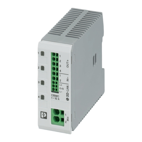
Phoenix Contact CAPAROC Series User manual

User manual
CAPAROC: System and installation

Table of contents
109745_en_01 PHOENIX CONTACT 3 / 66
Table of contents
1 For your safety ...........................................................................................................................5
1.1 Identification of warning notes ............................................................................... 5
1.2 Qualification of users ............................................................................................. 5
1.3 Field of application of the product.......................................................................... 6
1.3.1 Intended use .......................................................................................... 6
1.3.2 Product changes .................................................................................... 6
1.4 Available documents ............................................................................................. 6
1.4.1 Documentation on the Internet ............................................................... 6
2 The CAPAROC product family ...................................................................................................7
2.1 CAPAROC, the modular system............................................................................ 7
2.2 Structure of the CAPAROC system ....................................................................... 8
2.3 Approvals .............................................................................................................. 9
2.4 Overview of the CAPAROC modules................................................................... 10
2.4.1 CAPAROC power modules .................................................................. 10
2.4.2 CAPAROC circuit breaker modules ..................................................... 11
2.4.3 CAPAROC current rails ........................................................................ 12
2.4.4 Housing versions, design, and dimensions .......................................... 13
3 Transport and unpacking .........................................................................................................21
3.1 Transport............................................................................................................. 21
3.2 Storage................................................................................................................ 21
3.3 Unpacking ........................................................................................................... 21
4 Mounting and removing modules .............................................................................................23
4.1 Safety notes for mounting and removal ............................................................... 23
4.2 Basic information about mounting ....................................................................... 24
4.3 Mounting the modules ......................................................................................... 25
4.4 Removing the modules........................................................................................ 26
4.5 Replacing a module............................................................................................. 26
4.6 Mounting distances ............................................................................................. 27
5 Connecting or removing cables ...............................................................................................29
5.1 Connecting cables............................................................................................... 29
5.2 Connecting the power supply .............................................................................. 29
5.2.1 Requirements for the power supply ..................................................... 29
5.2.2 Connecting the power supply ............................................................... 30
5.3 Removing cables................................................................................................. 30

CAPAROC system
4 / 66 PHOENIX CONTACT 109745_en_01
6 Startup .....................................................................................................................................31
6.1 Setting the nominal current.................................................................................. 31
6.1.1 Programming (1- and 4-channel circuit breakers) ................................ 31
6.1.2 Programming (2-channel circuit breakers) ........................................... 32
6.2 Connecting loads................................................................................................. 34
6.3 Diagnostic and status indicators.......................................................................... 34
6.3.1 Indicators on the power module ........................................................... 34
6.3.2 Indicators on the protective device ....................................................... 35
6.3.3 Flow chart for startup ........................................................................... 35
7 Process, parameter, and diagnostic data .................................................................................37
7.1 Process data ....................................................................................................... 37
7.1.1 Input process data slot 0/subslot 2 (global system data) ...................... 37
7.1.2 Output process data slot 0/subslot 2 (global system data) ................... 38
7.1.3 Input process data of CAPAROC E1 12-24DC/1-10A .......................... 39
7.1.4 Output process data of CAPAROC E1 12-24DC/1-10A ....................... 39
7.1.5 Input process data of CAPAROC E2 12-24DC/2-10A .......................... 40
7.1.6 Output process data of CAPAROC E2 12-24DC/2-10A ....................... 41
7.1.7 Input process data of CAPAROC E4 12-24DC/1-10A .......................... 42
7.1.8 Output process data of CAPAROC E4 12-24DC/1-10A ....................... 44
7.2 Parameter and diagnostic data (PDI channel) ..................................................... 45
7.2.1 Parameters and acyclic data slot 0/subslot 2 (global system da-
ta) ........................................................................................................ 45
7.2.2 Parameters and acyclic data slot 1 ...16 ............................................... 48
7.3 Web server .......................................................................................................... 51
8 Updating the CAPAROC PM PN firmware ...............................................................................53
8.1 General information ............................................................................................. 53
8.2 Preparing the update ........................................................................................... 53
8.3 Performing the update ......................................................................................... 56
9 After use ..................................................................................................................................59
9.1 Device replacement............................................................................................. 59
9.2 Device defect and repair...................................................................................... 59
9.3 Maintenance........................................................................................................ 59
9.4 Decommissioning and disposal........................................................................... 60
A Appendix for document lists......................................................................................................61
A 1 List of figures ....................................................................................................... 61
A 2 List of tables ........................................................................................................ 63

For your safety
109745_en_01 PHOENIX CONTACT 5 / 66
1 For your safety
Read this user manual carefully and keep it for future reference.
1.1 Identification of warning notes
1.2 Qualification of users
The use of products described in this user manual is oriented exclusively to:
– Electrically skilled persons or persons instructed by them. The users must be familiar
with the relevant safety concepts of automation technology as well as applicable stan-
dards and other regulations.
– Qualified application programmers and software engineers. The users must be familiar
with the relevant safety concepts of automation technology as well as applicable stan-
dards and other regulations.
This symbol indicates hazards that could lead to personal injury.
There are three signal words indicating the severity of a potential injury.
DANGER
Indicates a hazard with a high risk level. If this hazardous situation is not avoided,
it will result in death or serious injury.
WARNING
Indicates a hazard with a medium risk level. If this hazardous situation is not
avoided, it could result in death or serious injury.
CAUTION
Indicates a hazard with a low risk level. If this hazardous situation is not avoided,
it could result in minor or moderate injury.
This symbol together with the NOTE signal word warns the reader of actions that
might cause property damage or a malfunction.
Here you will find additional information or detailed sources of information.

CAPAROC system
6 / 66 PHOENIX CONTACT 109745_en_01
1.3 Field of application of the product
1.3.1 Intended use
CAPAROC is a modular circuit breaker system. The devices correspond to protection class
IP20. They are intended for use in closed control cabinets or control boxes (junction boxes)
with IP54 degree of protection or higher.
The devices are designed for use in industrial environments.
1.3.2 Product changes
Modifications to the device hardware are not permitted. Modifications to the firmware are
only permitted by means of firmware updates provided by Phoenix Contact.
Incorrect operation or modifications to the device can endanger your safety or damage the
device. Do not repair the device yourself. If the device is defective, please contact
Phoenix Contact.
1.4 Available documents
1.4.1 Documentation on the Internet
The documentation can be downloaded at phoenixcontact.net/products. Here you will find
information on each product. You can obtain a summary of the technical data by selecting
“Generate product PDF”; other important documents can be found on the “Downloads” tab.
Generate product PDF Click the “Generate product PDF” button to receive selected up-to-date information. This
provides a brief overview of the module. The generated PDF file contains the essential prod-
uct information. If you require further information, you can use the “Downloads” tab.
Downloads On the “Downloads” tab, you can access the complete documentation and all other down-
loads related to a product. Module-specific documentation can be found in the download
area for the corresponding module.
Table 1-1 Available documents
Document Contents
User manual This user manual is the generic system manual for
CAPAROC. It describes the CAPAROC product group and
everything about mounting, removal, and wiring of
CAPAROC modules.
Installation notes The installation notes are included with every power module
and are available to download via the website.

The CAPAROC product family
109745_en_01 PHOENIX CONTACT 7 / 66
2 The CAPAROC product family
2.1 CAPAROC, the modular system
CAPAROC is an electronic circuit breaker system for use in control cabinets. Simply extend
the system via the rear current rail.
Your advantages
– The customizable standard, thanks to a wide range of possible combinations of the fu-
ture-proof modular system
– Easy operation for everyone through tool-free assembly, uninterrupted installation, and
transparent operating state
– Strikingly simple design-in with extensive support from the selection up to digital ser-
vices

CAPAROC system
8 / 66 PHOENIX CONTACT 109745_en_01
2.2 Structure of the CAPAROC system
A CAPAROC system consists of individual modules, which are snapped onto a DIN rail via
a current rail.
The power module forms the head of the station. The circuit breaker modules are connected
to the right of it.
The connection between the power module and the individual CAPAROC modules is estab-
lished via the side bus connectors. The internal CAPAROC bus is formed automatically
when the various CAPAROC modules are snapped on.
Figure 2-1 Example of a CAPAROC system
1 DIN rail
2 End bracket
3 Power module
4 2-channel 2 - 10 A circuit breaker
5 1-channel 1 - 10 A circuit breaker
6 Potential distribution module
7 Current rail
1
2
7
345
6

The CAPAROC product family
109745_en_01 PHOENIX CONTACT 9 / 66
2.3 Approvals
For the latest approvals for a product, please visit phoenixcontact.net/products.
• Go to the page for the relevant product.
• Switch to the “Approvals” tab.
The current approvals for the product are listed.
Observe any notes and restrictions for the approvals in the module-specific packing
slip or in the module-specific documentation.

CAPAROC system
10 / 66 PHOENIX CONTACT 109745_en_01
2.4 Overview of the CAPAROC modules
2.4.1 CAPAROC power modules
Figure 2-2 PM PN and PM S-R power modules
Table 2-1 Overview of power modules
Designation Item number Description
CAPAROC PM S-R 1115661 power module status-reset for supplying the system with the re-
quired voltage. Query system messages via a group message from
the module. A reset input and an I>80% signal output provide ad-
ditional diagnostics and reset options.
CAPAROC PM PN 1110986 power module for supplying the system with the required voltage
and PROFINET interface. The system provides extended diagnos-
tics and control options via the integrated interface.

The CAPAROC product family
109745_en_01 PHOENIX CONTACT 11 / 66
2.4.2 CAPAROC circuit breaker modules
Figure 2-3 Example: 1-channel, 2-channel, and 4-channel circuit breaker modules
Adjustable circuit breaker modules
Non-adjustable circuit breaker modules (fixed values)
Table 2-2 Overview of adjustable circuit breaker modules
Designation Item number Description
1-channel electronic circuit breakers
CAPAROC E1 12-24DC/1-4A 1115415 Adjustable from 1 - 4 A
CAPAROC E1 12-24DC/1-10A 1115649 Adjustable from 1 - 10 A
2-channel electronic circuit breakers
CAPAROC E2 12-24DC/1-4A 1115655 Adjustable from 1 - 4 A
CAPAROC E2 12-24DC/2-10A 1110984 Adjustable from 2 - 10 A
(adjustable from 1 - 10 A via bus-capable power module)
4-channel electronic circuit breakers
CAPAROC E4 12-24DC/1-4A 1115657 Adjustable from 1 - 4 A
CAPAROC E4 12-24DC/1-10A 1115658 Adjustable from 1 - 10 A
Table 2-3 Overview of non-adjustable circuit breaker modules (fixed values)
Designation Item number Description
1-channel electronic circuit breakers
CAPAROC E1 12-24DC/1A 1157288 1 A nominal current
CAPAROC E1 12-24DC/2A 1157290 2 A nominal current
CAPAROC E1 12-24DC/4A 1157285 4 A nominal current
CAPAROC E1 12-24DC/6A 1157286 6 A nominal current
CAPAROC E1 12-24DC/8A 1157279 8 A nominal current
CAPAROC E1 12-24DC/10A 1157284 10 A nominal current

CAPAROC system
12 / 66 PHOENIX CONTACT 109745_en_01
2.4.3 CAPAROC current rails
Figure 2-4 Example: CR 20 and CR EXT8 current rails
Table 2-4 Overview of current rails
Designation Item number Description
Basic current rails
CAPAROC CR 8 1115672 Rear current rail for distributing the supply voltage with an overall
width of 8 HP (49.2 mm).
CAPAROC CR 20 1110989 Rear current rail for distributing the supply voltage with an overall
width of 20 HP (123 mm).
Extension current rails
CAPAROC CR EXT4 1110991 Rear current rail for extending the system and distributing the sup-
ply voltage with an overall width of 4 HP (24.6 mm).
CAPAROC CR EXT8 1110990 Rear current rail for extending the system and distributing the sup-
ply voltage with an overall width of 8 HP (49.2 mm).
CAPAROC CR EXT20 1115674 Rear current rail for extending the system and distributing the sup-
ply voltage with an overall width of 20 HP (123 mm).

The CAPAROC product family
109745_en_01 PHOENIX CONTACT 13 / 66
2.4.4 Housing versions, design, and dimensions
Figure 2-5 Housing versions
PM PN PM S-R PD 0V
E1 E2 E4
Table 2-5 Overview of housing versions
Housing
type
Special feature Example Design Dimensions
PM PN power module with PROFINET CAPAROC PM PN Figure 2-6 on
page 14
Figure 2-7 on
page 14
PM S-R power module with status-reset CAPAROC PM S-R Figure 2-8 on
page 15
Figure 2-9 on
page 15
E1 1-channel circuit breaker CAPAROC E1 12-24DC/1-10A Figure 2-10 on
page 16
Figure 2-11 on
page 16
E2 2-channel circuit breaker CAPAROC E2 12-24DC/2-10A Figure 2-12 on
page 17
Figure 2-13 on
page 17
E4 4-channel circuit breaker CAPAROC E4 12-24DC/1-10A Figure 2-14 on
page 18
Figure 2-15 on
page 18
PD 0V 0 V potential distributor CAPAROC PD 0V Figure 2-16 on
page 19
Figure 2-17 on
page 19

The CAPAROC product family
109745_en_01 PHOENIX CONTACT 17 / 66
CAPAROC E2 ... circuit breaker
Figure 2-12 Design of CAPAROC E2 ...
Figure 2-13 Dimensional drawing of CAPAROC E2 ...
1 LED button channel 1 5 Load output channel 1
2 Rotary switch channel 1 6 Load output channel 2
3 LED button channel 2 7 Release
4 Rotary switch channel 2
1
2
3
4
5
6
7
111,3
132,4
12,4

CAPAROC system
18 / 66 PHOENIX CONTACT 109745_en_01
CAPAROC E4 ... circuit breaker
Figure 2-14 Design of CAPAROC E4 ...
Figure 2-15 Dimensional drawing of CAPAROC E4 ...
1 LED button channel 1 6 Load output channel 2
2 LED button channel 2 7 Load output channel 3
3 LED button channel 3 8 Load output channel 4
4 LED button channel 4 9 Release
5 Load output channel 1
1
2
3
4
5
6
9
7
8
111,3
132,4
12,4
This manual suits for next models
38
Table of contents
Other Phoenix Contact Circuit Breaker manuals