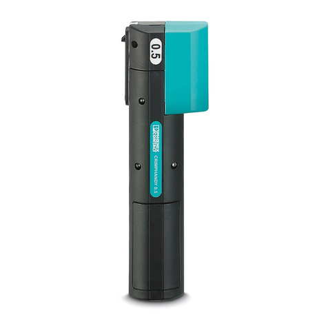
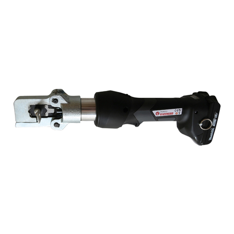
Phoenix Contact CF CRIMPHANDY 0,5 User manual

Original operating instructions
Operation of the
CF CRIMPHANDY portable
crimping tool
UM EN CF CRIMPHANDY
Order No. 2910936


2016-09-06
105555_en_07 PHOENIX CONTACT
Operation of the CF CRIMPHANDY portable crimping tool
UM EN CF CRIMPHANDY
07
2910936
Designation Order No.
CF CRIMPHANDY 0,5 1212463
CF CRIMPHANDY 0,75 1212464
CF CRIMPHANDY 1,0 1212465
CF CRIMPHANDY 1,5 1212466
Original operating instructions
Designation:
Revision:
Order No.:
This user manual is valid for:

PHOENIX CONTACT
Please observe the following notes
User group of this manual
The use of products described in this manual is oriented exclusively to qualified electricians
or persons instructed by them, who are familiar with applicable standards and other regula-
tions regarding electrical engineering and, in particular, the relevant safety concepts.
Explanation of symbols used and signal words
How to contact us
Internet Up-to-date information on Phoenix Contact products and our Terms and Conditions can be
found on the Internet at:
phoenixcontact.com
Make sure you always use the latest documentation.
It can be downloaded at:
phoenixcontact.net/products
Subsidiaries If there are any problems that cannot be solved using the documentation, please contact
your Phoenix Contact subsidiary.
Subsidiary contact information is available at phoenixcontact.com.
Published by PHOENIX CONTACT GmbH & Co. KG
Flachsmarktstraße 8
32825 Blomberg
GERMANY
Should you have any suggestions or recommendations for improvement of the contents and
layout of our manuals, please send your comments to:
This is the safety alert symbol. It is used to alert you to potential personal injury
hazards. Obey all safety measures that follow this symbol to avoid possible in-
jury or death.
There are three different categories of personal injury that are indicated with a
signal word.
DANGER This indicates a hazardous situation which, if not avoided, will re-
sult in death or serious injury.
WARNING This indicates a hazardous situation which, if not avoided, could
result in death or serious injury.
CAUTION This indicates a hazardous situation which, if not avoided, could
result in minor or moderate injury.
This symbol together with the signal word NOTE and the accompanying text
alert the reader to a situation which may cause damage or malfunction to the
device, hardware/software, or surrounding property.
This symbol and the accompanying text provide the reader with additional in-
formation or refer to detailed sources of information.

PHOENIX CONTACT
General terms and conditions of use for technical documentation
Phoenix Contact reserves the right to alter, correct, and/or improve the technical documen-
tation and the products described in the technical documentation at its own discretion and
without giving prior notice, insofar as this is reasonable for the user. The same applies to any
technical changes that serve the purpose of technical progress.
The receipt of technical documentation (in particular user documentation) does not consti-
tute any further duty on the part of Phoenix Contact to furnish information on modifications
to products and/or technical documentation. You are responsible to verify the suitability and
intended use of the products in your specific application, in particular with regard to observ-
ing the applicable standards and regulations. All information made available in the technical
data is supplied without any accompanying guarantee, whether expressly mentioned, im-
plied or tacitly assumed.
In general, the provisions of the current standard Terms and Conditions of Phoenix Contact
apply exclusively, in particular as concerns any warranty liability.
This manual, including all illustrations contained herein, is copyright protected. Any
changes to the contents or the publication of extracts of this document is prohibited.
Phoenix Contact reserves the right to register its own intellectual property rights for the
product identifications of Phoenix Contact products that are used here. Registration of such
intellectual property rights by third parties is prohibited.
Other product identifications may be afforded legal protection, even where they may not be
indicated as such.

CF CRIMPHANDY
6PHOENIX CONTACT 105555_en_07
Table of contents
1 Basic information .......................................................................................................................7
1.2 Correct use of the battery and charger ..................................................................9
1.3 Scope of supply...................................................................................................10
1.4 Operating elements .............................................................................................10
2 Operating the crimping tool ......................................................................................................11
2.1 Charging the battery ............................................................................................11
2.2 Switching on the crimping tool .............................................................................12
2.3 Inserting the taped ferrule ....................................................................................13
2.4 Crimping ..............................................................................................................14
2.5 Loading the taped ferrule.....................................................................................15
2.6 Removing the battery ..........................................................................................15
3 Troubleshooting .......................................................................................................................16
3.1 Overview of possible faults ..................................................................................17
3.2 Meaning of the indicator lights .............................................................................18
3.3 Troubleshooting sequences ................................................................................19
3.4 Removing the conductor......................................................................................20
3.5 Removing the ferrule ...........................................................................................21
3.6 Relieving blockage at ferrule transport.................................................................22
3.7 Removing loose parts..........................................................................................24
3.8 Initializing the crimping tool (Reset) .....................................................................26
3.9 Replacing waste guide plates ..............................................................................27
3.9.1 Replacing waste guide plate GP1 ........................................................27
3.9.2 Replacing waste guide plate GP2 ........................................................29
3.10 Returning a product .............................................................................................32
A Appendix..................................................................................................................................33
A 1 Ordering data.......................................................................................................33
A 2 Technical data .....................................................................................................35

Basic information
105555_en_07 PHOENIX CONTACT 7
English
1 Basic information
The portable crimping tool strips conductors in one step and crimps on a ferrule. It crimps
ferrules in square form.
The crimping tool is equipped with an inductive sensor which checks the actual conductor
cross section. If the cross section exceeds or falls below the defined limits, the crimping tool
does not trigger. The LEDs signal when a cross section is detected as being unsuitable.
In exceptional cases, conductors can be processed although they are not suitable. This
leads of crimp results that do not conform with the standards.
1.1 Suitable conductors and ferrules
Suitable conductors The mobile crimping tool is designed to process fine strand class 5 conductors according to
IEC 60228 with PVC insulation. Only use type H05V-K and H07V-K conductors. Conduc-
tors with very hard insulation such as rubber, silicone, Teflon, and textile insulation are not
suitable.
Avoid processing conductors that are very cold (e.g., directly from an unheated ware-
house). The colder the materials to be processed are, the harder and more resistant they
become. This can lead to increased wear or to mechanical damage.
Please note that the crimping tool can only process a specific conductor cross section. A
significantly deviating conductor cross section is detected and not processed. It may be
possible to process similar conductor cross sections, but this could endanger the electrical
connection. Make sure that conductor cross section and ferrules fit together.
NOTE: To ensure error-free use and the process reliability of the portable crimp-
ing tool, only use the conductors and ferrules described.
Using unsuitable materials may damage the crimping tool and lead to inferior work results.
We recommend that you check the quality of the crimp connections every 5000 cycles or
at the latest after a year.
Device type Conductor cross
section, metric
Outside diame-
ter
Conductor type
CF CRIMPHANDY 0,5 0.5 mm² 1.7 mm ... 2.4 mm H05V-K
CF CRIMPHANDY 0,75 0.75 mm² 1.9 mm ... 2.6 mm H05V-K
CF CRIMPHANDY 1,0 1.0 mm² 2.0 mm ... 2.7 mm H05V-K
CF CRIMPHANDY 1,5 1.5 mm² 2.4 mm ... 3.1 mm H07V-K

CF CRIMPHANDY
8PHOENIX CONTACT 105555_en_07
Wire check For checking the outside conductor diameter, the mobile crimping tool has two openings
that are labeled "wire check". The conductor has to fit in the opening that is labeled with the
checkmark. If the conductor fits in the small opening with the cross, then it may not be used.
Conductors that are too thick or too thin cause the crimping tool to be damaged.
Figure 1-1 Checking the outside diameter of the conductor
Suitable ferrules Only use taped ferrules from Phoenix Contact that have a specific function end. This special
design is required for safe operation.
Preparing the conductor In order to ensure optimum operation of the portable crimping tool, the conductor must be
prepared correctly. Make sure that the conductors are always cut straight. Conductors that
have been squeezed, cut at an angle or already stripped must not be used. Even for very
short conductors it may happen that they are not crimped correctly.
Only use cable cutters with sharp blades which cut the conductors and do not squeeze
them. Do not use diagonal cutters or similar unsuitable tools.
Quality of the crimping re-
sult
The quality of the crimping result depends on:
– The stranding of the conductor
– The processing temperature
– The tolerance at the cross section
wire check
Device type Taped ferrules from Phoenix Contact
CF CRIMPHANDY 0,5 AI 0,5-8 WH-S, 1212521 AI 0,5-8 OG-S, 1212784
CF CRIMPHANDY 0,75 AI 0,75-8 GY-S, 1212522 AI 0,75-8 BU-S, 1212785
AI 0,75-8 WH-S, 1212783
CF CRIMPHANDY 1,0 AI 1,0-8 RD-S, 1212523 AI 1,0-8 YE-S, 1212782
CF CRIMPHANDY 1,5 AI 1,5-8 BK-S, 1212524 AI 1,5-8 RD-S, 1212781
NOTE: The user has to make sure that only suitable materials are used.

Basic information
105555_en_07 PHOENIX CONTACT 9
English
1.2 Correct use of the battery and charger
The portable crimping tool works with a lithium-ion battery which is sufficient for up to 2000
crimping operations. The wide range power supply unit can be used worldwide with a mains
plug adapter.
Note the following when charging the battery
– To ensure a long service life for the lithium-ion battery, store it without charging it.
– Charge the battery at ambient temperatures from 0°C ...+40°C, ideally at 15°C ... 25°C.
– During charging, the indicator light on the charger lights up red. When fully charged, the
indicator light lights up green.
– Remove the battery from the charger once it has been fully charged and disconnect the
charger from the mains.
– The charging time is 60 minutes, the battery can be used after 20 minutes.
Notes on disposal
WARNING: Important safety notes for lithium-ion batteries
Risk of short circuit, fire, explosion, electric shock or damage to health
– Keep the battery away from metal objects. Paper clips, coins, keys, nails, and other
metal objects that touch the contacts may cause a short circuit.
– Do not submerge the battery in liquids.
– Do not heat or burn the battery.
– Never touch the contact surfaces of the charger.
– Do not open the battery housing. Do not break apart the cells.
Dispose of the used device and battery correctly
The portable crimping tool contains valuable recyclable materials, which should be uti-
lized after the useful life (lifecycle) of the device has ended.
In addition, the crimping tool is equipped with a lithium-ion battery which must be dis-
posed of in accordance with local regulations.
Please support us by contacting your local Phoenix Contact sales office to determine the
best way of returning the old device. Phoenix Contact will then handle the necessary re-
cycling and disposal measures.

CF CRIMPHANDY
10 PHOENIX CONTACT 105555_en_07
1.3 Scope of supply
1.4 Operating elements
Contents of the case
1Charger
2Cable cutters
3Battery
4Taped ferrules
5Crimping tool
6Service tool
1
2
3
6
5
4
Crimping tool
1Shaft for conductor
2Indicator lights
3Reset button
The reset button may only be used in the course of trou-
bleshooting as described in section 3.
4ON button
5Battery compartment
6Release button for battery compartment
7M5 thread for attaching the crimping tool to a balancer
8Wire check
9Window for ferrule magazine
10 Flap for opening the ferrule magazine
11 Waste container
12 Service cover
wire check
1 2
8
9
12
3 4 5 6 +7
1011

Operating the crimping tool
105555_en_07 PHOENIX CONTACT 11
English
2 Operating the crimping tool
2.1 Charging the battery
NOTE: Only use the crimping tool at ambient temperatures of +15° C ... +30°C.
NOTE: Do not remove the battery during the crimping process.
Unlocking the battery compartment
•Press the release button on the bottom of the crimping tool. The
battery springs into the removal position.
•Remove the battery from the crimping tool.
The battery is already charged when delivered.
Charging the battery
•Place both pins of the battery in the recesses on the cable side
of the charger.
•Press down on the battery at the opposite end.
•Plug the mains plug into the socket.
During charging, the indicator light on the mains plug lights up
red. It changes to green when the charging process has been
completed.
Inserting the battery in the crimping tool
•Insert the battery in the battery compartment of the crimping
tool.
•Proceed in the same way as inserting the battery in the charger.
The recesses are towards the front of the device.
The battery engages with a click.
AB
NOTE: When doing so, observe the section "Correct
use of the battery and charger" on Page 9.
AB

CF CRIMPHANDY
12 PHOENIX CONTACT 105555_en_07
2.2 Switching on the crimping tool
Switching on the crimping tool
•Press the ON button briefly. The green indicator light flashes.
The crimping tool is ready for use. The yellow light flashes if no
taped ferrule is inserted.
•If the ON button is held down longer when switching on, the
three indicator lights indicate the charging state of the battery.
– Green on = battery full
– Yellow on = battery half full
– Red on = battery almost empty
Troubleshooting
•When the green and red indicator lights flash simultaneously,
the battery is empty. Follow the instructions for charging the
battery (see Page 11).
•If the yellow indicator light flashes, follow the sequence for in-
serting a taped ferrule (see Page 13).
Switching off the crimping tool
•Press the ON button for approx. three seconds. The three indi-
cator lights briefly show the charging state of the battery.
After approximately five minutes of no activity, the crimping tool
switches itself off automatically.

Operating the crimping tool
105555_en_07 PHOENIX CONTACT 13
English
2.3 Inserting the taped ferrule
The yellow indicator light flashes.
•If the yellow indicator light is not flashing, do not insert a taped
ferrule under any circumstances.
Removing the waste container
•Using your thumb, slide the waste container towards the front
of the device and remove it with a downward motion.
Opening the lid
•Flip the lid upwards to open. There will be slight resistance
when doing this.
Inserting the taped ferrule
•Insert the taped ferrule, starting with the function end (four plas-
tic ferrules), as far as it will go to the right into the guide shaft.
•Then push the taped ferrule to the left as far as it will go into the
guide shaft until it engages.
Closing the lid and attaching the waste container
•Close the lid.
•When attaching the waste container, place it so that it is flush
with the lid (the waste container will be around five millimeters
over the front edge of the crimping tool).
•Push the waste container into the end position parallel to the
crimping tool until it snaps in and is flush with the front of the de-
vice.
Loading the taped ferrule
•Press the ON button.
You hear a sound of movement and the green indicator light
flashes. The crimping tool is ready for use.
NOTE: Only use suitable taped ferrules (see Page 8).
These tapes have a function end that is required for er-
ror-free operation. Do not insert damaged or bent tapes.
CLICK !

CF CRIMPHANDY
14 PHOENIX CONTACT 105555_en_07
2.4 Crimping
Cutting conductor to size
•Cut the conductor straight and cleanly with a CUTFOX 12 cable
cutters. These cable cutters are supplied as standard.
a) Proper cut
b) Cut surface squeezed
c) Cut surface angled
d) Litz wires are longer than the insulation
e) Litz wires are shorter than the insulation
•Optionally, a cutting unit is available which is attached to the
crimping tool (CF CRIMPHANDY CUTTER, 1212520).
Inserting the conductor
•Insert the conductor straight and without force into the shaft.
It may be helpful to turn the conductor slightly around its own
axis.
The conductor is processed. You hear a crimping sound.
As soon as the conductor is being processed, you must not pull
or push at it
•When after approx. two seconds the process is concluded, pull
the conductor out straight.
When the green indicator light flashes, the crimping tool is
ready for use again.
NOTE: Damage to the crimping tool
Make sure that the conductors are always cut straight.
Conductors that have been squeezed, cut at an angle or
already stripped must not be used.
Only use cable cutters with sharp blades which cut the
conductors and do not squeeze them. Do not use diag-
onal cutters or similar unsuitable tools.
ab
cd e
2 s
A
B
We recommend checking the pull-out forces regularly.
Check if ferrule and conductor are correctly crimped.

Operating the crimping tool
105555_en_07 PHOENIX CONTACT 15
English
2.5 Loading the taped ferrule
2.6 Removing the battery
The yellow indicator light flashes. The ferrule magazine is empty.
•Remove the waste container and dispose of the insulation rem-
nants.
Opening the lid
•Flip the lid upwards to open. There will be slight resistance
when doing this.
Removing the remnants of the tape
•Push the slide towards the front of the device.
•Hold the slide in this position and remove the remnants of the
tape. Please make sure that the remnants of the tape do not fall
into the guide shaft.
Inserting the taped ferrule
•See Page 13.
NOTE: Damage to the crimping tool
Never remove the battery during the crimping process or troubleshooting. The conductor
should be taken out before the battery is removed.
The green and red indicator lights flash simultaneously at short in-
tervals. The battery is empty and has to be charged.
Unlocking the battery compartment
•Press the release button on the bottom of the crimping tool. The
battery springs into the removal position.
•Remove the battery from the crimping tool.
Charging the battery
•See Page 11.

CF CRIMPHANDY
16 PHOENIX CONTACT 105555_en_07
3 Troubleshooting
NOTE: Damage to the crimping tool
Faults, such as a jammed conductor, can be remedied using the steps described below.
Never remove the battery during troubleshooting.
You may open the service cover to shake out loose parts. Do not loosen the screws of the
housing to open it. This can damage the crimping tool.
The print “DO NOT OPEN” on the crimping tool indicates that the crimping tool will be
damaged if the housing is opened.

Troubleshooting
105555_en_07 PHOENIX CONTACT 17
English
3.1 Overview of possible faults
Error Cause Solution
The device will not switch on – Problems with the power supply – Check the battery
– Clean the battery compartment
The green indicator light
flashes, but the device does
not trip or the conductor can-
not be inserted
– The battery was removed during a crimp-
ing cycle
– Problems with the power supply
– The conductor is not recognized
– The crimping unit has been shifted manu-
ally
– Initialize device (see Page 26)
The green indicator light
flashes, but there is still a con-
ductor in the device
– The conductor was not correctly prepared
(see Page 14)
– The conductor was inserted with too
much force
– The conductor was pulled out too early
– The conductor does not correspond to the
specifications
– Carefully turn the conductor and pull
it out
– The battery was removed during the
crimping process
– Screw in the service tool and re-
move the conductor
– Then initialize device (see Page 26)
The green and red indicator
lights flash slowly, but the con-
ductor is correct
– The conductor is not recognized
– The conductor is recognized as having an
incorrect cross-section
– Switch off the device without the
conductor, and then switch on again
– Check the stranding of the wires
– Check if the conductor corresponds
to the specifications
– Check the temperature range
Errors re-occur several times – The conductor does not correspond tothe
specifications
– Check if the conductor corresponds
to the specifications
– Wear of the stripping blade
Indications for wear of the blade are rough
and asymmetrical cut edges on the insu-
lation remnants in the waste container
– Please contact Phoenix Contact
– The conductor was not correctly prepared
(see Page 14).
– Prepare the conductor according to
specifications

CF CRIMPHANDY
18 PHOENIX CONTACT 105555_en_07
3.2 Meaning of the indicator lights
Green Yellow Red Meaning or action For remedy
see
Long
flashing – – Ready for operation –
Short
flashing –Short
flashing Battery is empty Page 15
Long
flashing –Long
flashing Conductor cross section is too small or too big –
–Long
flashing – Insert taped ferrule. Press the ON switch. Page 13
–On–
Remove the taped ferrule. If none is inserted, actuate
the tape slide. Page 22
On On On
A conductor is stuck in the crimping tool. Screw in the
service tool on the threaded side and remove the con-
ductor.
Page 20
– On On Press the reset button. –
––On
Check if a ferrule without conductor is stuck in the
crimping tool. To do so, push in the service tool on the
plastic side until the red indicator light goes out. Then
carefully remove the service tool.
Page 21
––
Long
flashing
Open the service cover. Remove loose parts from the
device and close the service cover again.
First remove any conductor that is stuck in the device.
For this, screw in the service tool on the threaded side
and remove the conductor.
Remove the service tool. Press the ON switch.
Page 24
Running light
No action is required if the running light appears briefly.
If the running light appears continuously, start initializ-
ing the device. If this does not work, please contact
Phoenix Contact.
Page 26

Troubleshooting
105555_en_07 PHOENIX CONTACT 19
English
3.3 Troubleshooting sequences
The diagram of the sequences is to provide you with an overview. The crimping tool guides
the user through the entire troubleshooting procedure
Removing the conductor (Page 20) Relieving a blockage
• Screwtheservicetoolintothebore
hole.
• Pull out the conductor.
• Remove the service tool.
• Using the service tool, remove any
conductor that might still be stuck in the device.
• Actuate the tape slide.
• Remove the taped ferrule, if present.
Relieving blockage at ferrule transport
(Page 22) Removing loose parts (Page 24)
• Press the reset button. • Press the reset button. • Open the service cover.
• Remove loose parts.
Removing the ferrule (Page 21)
• Insert the service tool into the shaft.
• The red indicator light goes out.
• Carefully remove the service tool.
Ferrule removed Ferrule not
removed
• Close the service cover.
• Press the ON switch.
Ready for opera-
tion
• Insert taped ferrule.
• Press the ON switch.
Repeat the
sequence
"Relieving a
blockage".
• Insert taped ferrule.
• Press the ON switch.
Ready for opera-
tion
Ready for opera-
tion
Repeat the
sequence
"Relieving a
blockage".

CF CRIMPHANDY
20 PHOENIX CONTACT 105555_en_07
3.4 Removing the conductor
The three indicator lights light up simultaneously.
Following crimping, the conductor cannot be removed from the
crimping tool.
•Take the service tool from the storage case.
Removing the waste container
•Using your thumb, slide the waste container towards the front
of the device and remove it with a downward motion.
Screwing in the service tool and removing the conductor
On the bottom of the crimping tool you will see a bore hole with an
inner thread.
•Screw the service tool with the thread into the bore hole as far
as it will go. Make sure that the service tool is not screwed too
tight.
•Now carefully remove the conductor from the shaft.
•Screw out the service tool again.
•Reattach the waste container (see Page 13).
The yellow and red indicator lights light up.
•Press the reset button with the service tool.
If the red indicator light lights up, follow the sequence for remov-
ing a ferrule from the shaft (see Page 21).
B
C
A
NOTE: Under no circumstances should you press the
reset button while the service tool is screwed in. This will
damage the crimping tool.
This manual suits for next models
8
Table of contents
Other Phoenix Contact Crimping Tools manuals