Phoenix Contact IOL MA8 PN DI8 User manual

User manual
UM EN IOL MA8 PN DI8
IO-Link to PROFINET and Modbus TCP
gateway

Table of contents
4022_en_A PHOENIX CONTACT 1
Table of contents
1 For your safety............................................................................................................................3
1.1 Labeling of warning notes...................................................................................... 3
1.2 Qualification of users ............................................................................................. 3
1.3 Field of application of the product.......................................................................... 4
1.3.1 Intended use .......................................................................................... 4
1.3.2 Foreseeable misuse ............................................................................... 4
1.3.3 Product changes .................................................................................... 4
1.4 Acknowledgments ................................................................................................. 4
2 Description..................................................................................................................................5
2.1 Overview ............................................................................................................... 5
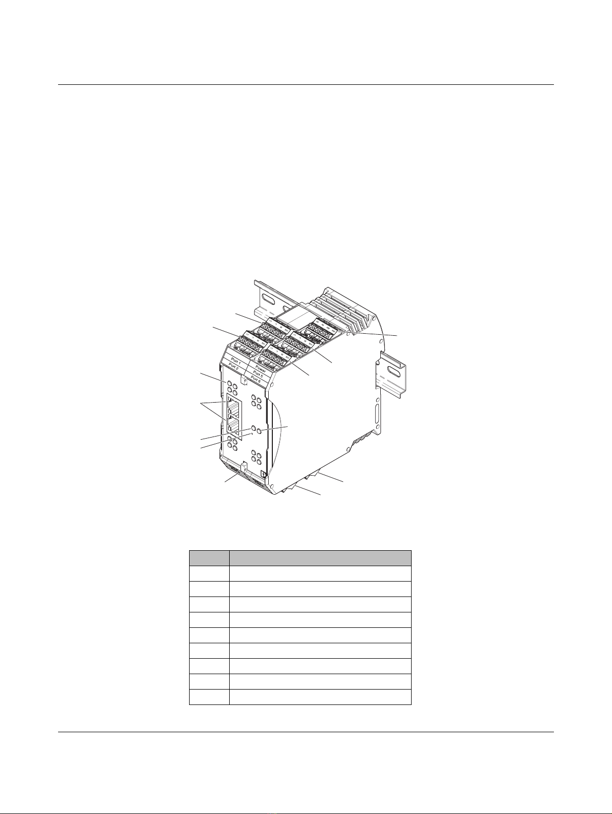
2.2 Structure................................................................................................................ 5
2.3 System example.................................................................................................... 6
3 Installation ..................................................................................................................................7
3.1 Mounting ............................................................................................................... 7
3.2 Data interfaces ...................................................................................................... 8
3.2.1 Connecting the Ethernet cable ............................................................... 8
3.3 Connecting the power supply ................................................................................ 9
3.4 Connecting devices to IOL MA8 PN DI8 ports ..................................................... 10
4 Configuration and startup..........................................................................................................13
4.1 Default settings.................................................................................................... 13
4.2 Web-based management .................................................................................... 13
4.2.1 Login .................................................................................................... 14
4.2.2 Home page .......................................................................................... 15
4.2.3 Selecting a language ........................................................................... 15
5 Web manager interface ............................................................................................................17
5.1 Diagnostics.......................................................................................................... 17
5.1.1 IO-Link diagnostics .............................................................................. 19
5.1.2 PROFINET IO diagnostics ................................................................... 22
5.1.3 Modbus TCP diagnostics ..................................................................... 25
5.1.4 OPC UA diagnostics ............................................................................ 28

IOL MA8 PN DI8
2PHOENIX CONTACT 4022_en_A
5.2 Configuration ....................................................................................................... 28
5.2.1 Preparing for port configuration ............................................................ 28
5.2.2 IO-Link configuration ............................................................................ 31
5.2.3 PROFINET IO configuration ................................................................. 39
5.2.4 Modbus TCP configuration .................................................................. 40
5.2.5 OPC UA configuration .......................................................................... 45
5.2.6 LAN settings ........................................................................................ 47
5.2.7 Utilities ................................................................................................. 48
5.2.8 Configuration files ................................................................................ 51
5.3 Device maintenance............................................................................................ 53
5.3.1 Firmware .............................................................................................. 53
5.3.2 Accounts .............................................................................................. 55
5.3.3 Log files ............................................................................................... 57
5.3.4 Device snapshot .................................................................................. 59
5.4 Attached devices................................................................................................. 60
5.4.1 IODD files ............................................................................................ 60
5.4.2 IO-Link device configuration summary ................................................. 62
5.4.3 Port parameters ................................................................................... 64
6 Troubleshooting........................................................................................................................71
6.1 Troubleshooting................................................................................................... 71
6.2 Status LEDs......................................................................................................... 72
A Technical appendix...................................................................................................................75
A 1 Modbus TCP interface........................................................................................ 75
A 2 Modbus TCP address definitions........................................................................ 76
B Appendixes...............................................................................................................................77
B 1 List of figures ...................................................................................................... 77
B 2 List of tables ....................................................................................................... 79

For your safety
4022_en_A PHOENIX CONTACT 3
1Foryoursafety
Read this user manual carefully and keep it to hand for future reference.
The applicable specifications and safety directives (including the national safety directives),
as well as the general technical regulations, must be observed during installation and
operation. The technical data should be taken from the packaging instructions and the
certificates (conformity assessment, other possible approvals).
The IP20 degree of protection (EN 60529) of the device is intended for a clean and dry
environment.
Do not subject the device to any load that exceeds the prescribed limits.
The device is not designed for use in environments with danger of dust explosions.
1.1 Labeling of warning notes
1.2 Qualification of users
The use of products described in this user manual is oriented exclusively to:
– Qualified electricians or persons instructed by them. The users must be familiar with the
relevant safety concepts of automation technology as well as applicable standards and
other regulations.
– Qualified application programmers and software engineers. The users must be familiar
with the relevant safety concepts of automation technology as well as applicable
standards and other regulations.
This symbol indicates hazards that could lead to personal injury.
There are three signal words indicating the severity of a potential injury.
DANGER
Indicates a hazard with a high risk level. If this hazardous situation is not
avoided, it will result in death or serious injury.
WARNING
Indicates a hazard with a medium risk level. If this hazardous situation is not
avoided, it could result in death or serious injury.
CAUTION
Indicates a hazard with a low risk level. If this hazardous situation is not avoided,
it could result in minor or moderate injury.
This symbol together with the NOTE signal word alerts the reader to a situation
which may cause damage or malfunction to the device, hardware/software, or
surrounding property.
Find find additional information or detailed sources of information.

IOL MA8 PN DI8
4PHOENIX CONTACT 4022_en_A
1.3 Field of application of the product
1.3.1 Intended use
The IOL MA8 PN DI8 protocol converter provides convenient access to configure IO-Link
devices using web-based management. Sensor status may be monitored using
PROFINET, Modbus TCP, and OPC UA.
1.3.2 Foreseeable misuse
Phoenix Contact is not responsible for the logic within the device or any application that was
created using this product or devices described within this document.
1.3.3 Product changes
Changes or modifications to hardware and software of the device are not permitted.
Incorrect operation or modifications to the device can endanger safety or damage the
device. Do not repair the device yourself.
Opening the device or making changes to it is not permitted. Do not repair the device
yourself, but replace it with an equivalent device. Repairs may be carried out only by the
manufacturer. The manufacturer is not liable for any damage caused by violation of the
prescribed regulations.
If the device is defective, please contact Phoenix Contact.
1.4 Acknowledgments
The developers of this product would like to thank the following open-source projects whose
work is used under the listed licenses.
Table 1-1 Open-source licenses
Software License Software License
Linux kernel GPLv2 buildroot GPLv2
Busybox GPLv2 file file
gdbserver GPLv3 json-c json-c
ipkg GPLv2 libpcap BSD-libpcap
lighttpd BSD-lighttpd lsof lsof
mtd GPLv2 nano GPLv3
netsnmp netsnmp openssh BSD-openssh
openssl BSD-openssl pcre PSD-pcre
php php strace BSD-strace
zlib BSD-zlib Open62541 Mozilla public
license

Description
4022_en_A PHOENIX CONTACT 5
2Description
2.1 Overview
The IOL MA8 PN DI8 provides the ability to configure up to eight IO-Link sensors using web-
based management and seamlessly integrates your IO-Link devices into your control
system using Modbus TCP, PROFINET, and OPC UA.
2.2 Structure
The IOL MA8 PN DI8 features two Ethernet ports, status LEDs, and connectors for power
and IO-Link ports.
Figure 2-1 IOL MA8 PN DI8 structure
Table 2-1 IOL MA8 PN DI8 structure
Item Description
1 Power connector
2 Port 1 IO-Link connector
3 Port 2 IO-Link connector
4 Port 3 IO-Link connector
5 Port 4 IO-Link connector
6 Port 5 IO-Link connector
7 Port 6 IO-Link connector
8 Port 7 IO-Link connector
9 Port 8 IO-Link connector
P3
P4
P7
P8
P1
DI C/Q DI C/Q
DIC/
QD
IC/Q
P2
P5
P6
NET
ACT LI NK ACT L INK
X2
X1
MOD
3
2
7
6
4, 5
11
9
8
13
10
14
12
1

IOL MA8 PN DI8
6PHOENIX CONTACT 4022_en_A
2.3 System example
The following diagram illustrates the IOL MA8 PN DI8 in a system configuration.
Figure 2-2 Typical system overview
10 Ethernet ports (RJ45)
11 Digital input and IO-Link port status LEDs
12 NET status LED
13 MOD status LED
14 Reset button
Table 2-1 IOL MA8 PN DI8 structure
Item Description
SIO
PSR switch
PSR-CT-F-SEN-1-8
Ord.-No.
2702976
PHOENIX
CONTACT
GmbH& Co. KG
32825Blomberg
Germany
DIAG
STATE
PSR-CT-C-ACT
Ord.-No.
2702973
PSR switch
P3
P4
P7
P8
P1
DI C/Q DI C/Q
DI C/Q DI C/Q
P2
P5
P6
NET
ACT LINK ACT LINK
X2
X1
MOD

Installation
4022_en_A PHOENIX CONTACT 7
3 Installation
3.1 Mounting
To mount on the DIN rail:
1. Place the device on to the DIN rail from above (1), so that the upper housing keyway
hooks on to the top edge of the DIN rail.
2. Hold the device by the housing cover and carefully push the device toward the
mounting surface (2).
3. After the foot is snapped on to the DIN rail, verify that it is attached securely.
Figure 3-1 DIN rail mounting
To remove:
1. Use a suitable screwdriver to release the locking mechanism (1) on the snap-on foot of
the device.
2. Hold on to the device by the housing cover and carefully tilt it upward (2).
3. Remove the device from the DIN rail (3).
Figure 3-2 DIN rail removal

IOL MA8 PN DI8
8PHOENIX CONTACT 4022_en_A
3.2 Data interfaces
3.2.1 Connecting the Ethernet cable
The IOL MA8 PN DI8 has an Ethernet interface on the front in RJ45 format, to which only
twisted-pair cables with an impedance of 100 Ωcan be connected. The data transmission
rate is either 10 or 100 Mbps. The IOL MA8 PN DI8 supports the auto negotiation function
for automatic selection of the transmission speed, as well as an automatic crossover feature
for the automatic selection of line or crossover cabling.
Push the Ethernet cable with the crimped RJ45 connector into the IOL MA8 PN DI8 until it
engages with a click.
The IOL MA8 PN DI8 Ethernet interface is classified as a switch. The maximum number of
daisy-chained IOL MA8 PN DI8 units, and the maximum distance between units, is based
on the Ethernet standards and is determined by the environment and conformity of the
network to these standards. There may be some performance degradation on the devices
at the end of the chain, so it is recommended to overload and test for performance in the
environment. The application may also limit the total number of ports that may be installed.
Some basic guidelines are listed below.
– Ethernet 10Base-T rules
– The maximum number of repeater segments is four.
– Use Category 3 or 5 twisted-pair 10Base-T cables. The maximum length of each
cable is 100 m.
– Fast Ethernet 100Base-TX rules
– The maximum number of repeater segments is two (for a Class II hub). A Class II
hub can be connected directly to one other Class II Fast Ethernet hub. A Class I hub
cannot be connected directly to another Fast Ethernet hub.
– CAT5 or greater twisted-pair cable must be used. The maximum length of each
twisted-pair cable is 100 m.
– The total length of twisted-pair cabling (across directly connected hubs) must not
exceed 205 m.
– IEEE 802.3 specification: A network using repeaters between communicating stations
(PCs) is subject to the 5-4-3 rule of repeater placement on the network:
– Five segments connected on the network.
– Four repeaters.
– Three segments of the fiber segments can have stations connected. The other two
segments must be inter-repeater link segments with no stations connected.

Installation
4022_en_A PHOENIX CONTACT 9
3.3 Connecting the power supply
The device can be connected to a single power source or two power sources for
redundancy. The IOL MA8 PN DI8 is powered using a +24 V DC SELV power supply. The
power supply is connected by way of push-in terminal blocks (24 V and 0 V).
Figure 3-3 Single power supply connection
Figure 3-4 Redundant power supply connection
CAUTION:
Incorrect connection may result in damage to equipment and/or serious personal injury.
Only qualified personnel may connect the power, start up, and operate this device.
According to the safety instructions in this text, qualified personnel are persons who are
authorized to start up, to ground, and to mark devices, systems, and equipment according
to the standards of safety technology. In addition, these persons must be familiar with all
warning instructions and maintenance measures in this text.
Disregarding this warning may result in damage to equipment and/or serious personal
injury.
0V0V24V24V
0V0V24V24V

IOL MA8 PN DI8
10 PHOENIX CONTACT 4022_en_A
3.4 Connecting devices to IOL MA8 PN DI8 ports
Figure 3-5 SIO connection
The following provides information about the power supply ports.
Connecting IO-Link devices
Use the following procedure to connect IO-Link devices to an IO-Link port.
1. Insert the IO-Link device negative wire into the L- position until the wire is fully secure.
2. Insert the IO-Link device positive wire into the L+ position until the wire is fully secure.
3. If applicable, insert the digital input signal wire into the DI position until the wire is fully
secure.
4. Insert the IO-Link wire into the C/Q position until the wire is fully secure.
5. If necessary, configure IO-Link parameters for each port.
Connecting digital input devices to IOL MA8 PN DI8 ports
Use the following procedure to connect a digital input device to an IO-Link port.
1. Insert the IO-Link device negative wire into the L- position until the wire is fully secure.
2. Insert the IO-Link device positive wire into the L+ position until the wire is fully secure.
3. Insert the digital input signal wire into the DI position until the wire is fully secure.
Table 3-1 Power supply port connections
Label Signal Description Value
1 L+ Power supply output (+) 200 mA @ 24 V
(Maximum)
2 L- Power supply output (-)
3 DI Digital input Not applicable
4 C/Q Communication signal, which supports
SDCI (IO-Link) or SIO (standard
input/output)
200 mA @ 24 V
(Maximum)
L+L-DIC/Q
IO-Link
SIO
It may be useful to remove the plug-in terminal block from the IOL MA8 PN DI8 to aid in
wire termination.

Installation
4022_en_A PHOENIX CONTACT 11
Connecting digital input or output devices to IOL MA8 PN DI8 ports
Use the following procedure to connect and operate a digital input or output device.
1. Insert the IO-Link device negative wire into the L- position until the wire is fully secure.
2. Insert the IO-Link device positive wire into the L+ position until the wire is fully secure.
3. If applicable, insert the digital input or output signal wire into the C/Q position until the
wire is fully secure.

IOL MA8 PN DI8
12 PHOENIX CONTACT 4022_en_A

Configuration and startup
4022_en_A PHOENIX CONTACT 13
4 Configuration and startup
4.1 Default settings
The default network settings of the IOL MA8 PN DI8 are:
IP address: 192.168.254.254
Subnet mask: 255.255.255.0
Gateway: 0.0.0.0
4.2 Web-based management
The user-friendly, web-based graphical user interface (GUI) allows management of the IOL
MA8 PN DI8 from anywhere in the network using a standard browser. Comprehensive
configuration and diagnostic functions, including a wide range of information about the
device itself, current parameters, and operating state, are clearly displayed.
Terminology for the GUI is shown below.
Figure 4-1 GUI terminology
The default settings are invoked whenever the system is reset.
Tab
Subtab
Page
Field
Group name

IOL MA8 PN DI8
14 PHOENIX CONTACT 4022_en_A
4.2.1 Login
To log in:
1. Set the IP address of the connected PC to the subnetwork of the IOL MA8 PN DI8. For
example:
IP = 192.168.254.10
Subnetwork = 255.255.255.0
2. Open a browser and enter the IP address of the IOL MA8 PN DI8 in the “Address” field
(default = 192.168.254.254).
Figure 4-2 “Login” screen
The web server responds immediately.
3. By default, a user name and password are not required. If user accounts have been
configured (see “Accounts” on page 55), enter the appropriate values in the
corresponding fields to log in.
4. Complete the IOL MA8 PN DI8 configuration as necessary for the application.
– Set the IP address (see “LAN settings” on page 47).
– Load the appropriate IODD files (see “IODD files” on page 60).
– Configure the IO-Link ports (see “IO-Link configuration” on page 31).
If the web server does not load, first check the IP parameters of the PC. If everything is set
correctly, check to see if there are any proxy settings loaded in the browser. The proxy
setting must be set to “Load automatically” or “Deactivated” to properly establish
communication.
Powering multiple devices with factory default IP addresses causes a network conflict, and
incorrect parameters may be set in the IOL MA8 PN DI8 modules. When programming
modules for the first time, it is important to apply power to only one at a time, and change
the IP address of each module to a unique IP address. Once all devices have a unique IP
address, they can be powered on together while on the same network.

Configuration and startup
4022_en_A PHOENIX CONTACT 15
4.2.2 Home page
The “Home” page displays general system information.
Figure 4-3 “Home” page
4.2.3 Selecting a language
Click the “Flag” icon to select the interface language, either English or German.

IOL MA8 PN DI8
16 PHOENIX CONTACT 4022_en_A

Web manager interface
4022_en_A PHOENIX CONTACT 17
5 Web manager interface
5.1 Diagnostics
This chapter provides information about the diagnostics pages.
To access the diagnostics pages:

IOL MA8 PN DI8
18 PHOENIX CONTACT 4022_en_A
1. If necessary, log in to the IOL MA8 PN DI8.
2. Click the “Diagnostics” tab, and then click the desired subtab. For example, to show the
“IO-Link Diagnostics” page, click the “IO-Link” subtab.
Figure 5-1 “IO-Link Diagnostics” page
3. Use the scroll bars to view all available information.
4. This data is updated with the “LIVE update” function providing constant updates. If
desired, click the “STOP LIVE UPDATES” button to stop the function. To update data
immediately, click the “UPDATE” button. Click the “RESET STATISTICS” button to
reset the statistics fields.
Table of contents
Other Phoenix Contact Gateway manuals