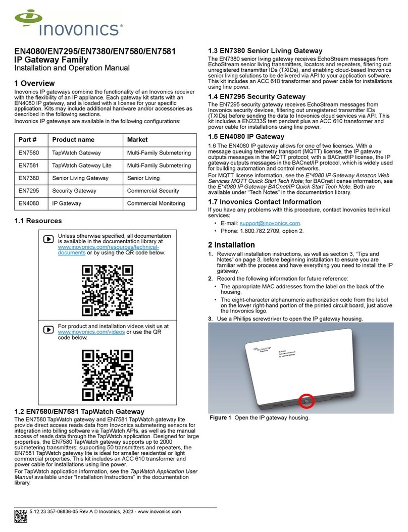
Inovonics EE4080 User manual

EE4080 IP Gateway
Installation Instructions
6.5.19 357-06982-02 Rev A © Inovonics, 2019
1 Overview
The EE4080 IP gateway combines the functionality of an Inovonics
receiver with the flexibility of an IP appliance, receiving EchoStream data
and outputting messages directly to an IP-based application.
2 Installation
1 Review all installation instructions, as well as section 3, “Tips and
Notes” on page 3, before beginning installation to ensure you are
familiar with the process and have everything you need to install
the IP gateway.
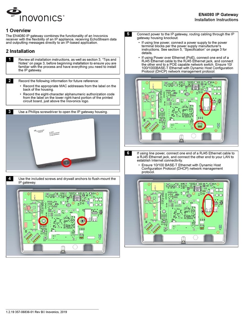
2 Record the following information for future reference:
• Record the appropriate MAC addresses from the label on the
back of the housing.
• Record the eight-character alphanumeric authorization code
from the label on the lower right-hand portion of the printed
circuit board, just above the Inovonics logo.
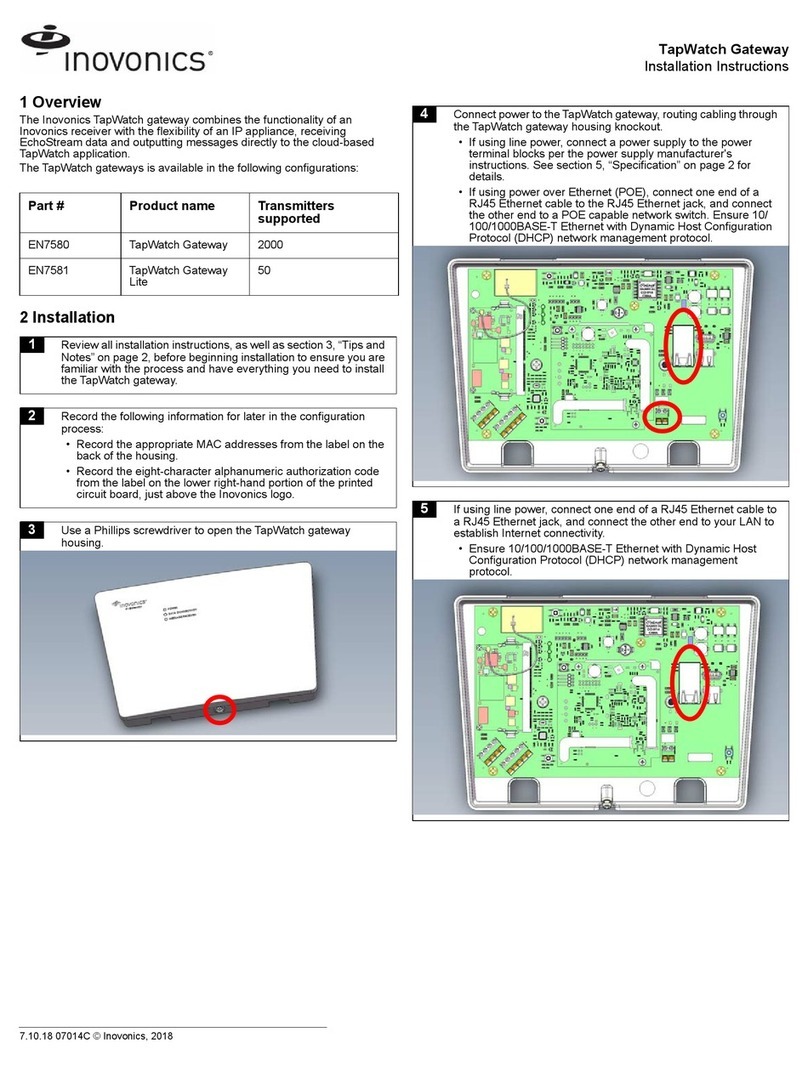
3 Use a Phillips screwdriver to open the IP gateway housing.
4 Use the included screws and drywall anchors to flush-mount the
IP gateway.
5 Connect power to the IP gateway, routing cabling through the IP
gateway housing knockout.
• If using line power, connect a power supply to the power
terminal blocks per the power supply manufacturer's
instructions. See section 5, “Specification” on page 3 for
details.
• If using Power over Ethernet (PoE), connect one end of a
RJ45 Ethernet cable to the RJ45 Ethernet jack, and connect
the other end to a PoE capable network switch. Ensure 10/
100BASE-T Ethernet with Dynamic Host Configuration
Protocol (DHCP) network management protocol.
6 If using line power, connect one end of a RJ45 Ethernet cable to
a RJ45 Ethernet jack, and connect the other end to your LAN to
establish Internet connectivity.
• Ensure 10/100BASE-T Ethernet and DHCP network
management protocol.
Note: Steps 7 through 12 are generic configuration instructions for the IP
gateway. For instructions for your individual license, see the
E*4080 IP Gateway Amazon Web Services MQTT Quick Start
Tech Note or the E*4080 IP Gateway BACnet/IP Quick Start Tech
Note available in the documentation library at www.inovonics.com.

6.5.19 357-06982-02 Rev A © Inovonics, 2019 2
7 If using an existing EE4080 configuration file, open the
configuration file and proceed to step 10; if using a new EE4080
configuration file:
a. Insert a brand-name USB flash drive into either of the IP
gateway's USB ports.
b. Download the configuration file to the USB drive by pressing
the reset button on the IP gateway.
c. When the red LED is solidly lit or blinking, remove the USB
drive.
d. Insert the USB drive into a PC.
8 On your PC, open the configuration file from the USB drive.
• It will be named ee4080-XX-config-YYYYMMDD-
HHMMSS.yaml, where XX is the last two hex digits of the
Ethernet MAC address, as shown on the label on the back of
the house, and YYYYMMDD-HHMMSS is the current date
and time.
9 Enter the configuration information into the .yaml file:
• Enter TXIDs for the transmitters and any repeaters to be
registered to the IP gateway, referring to and overwriting the
examples provided in the file, separated by commas.
• Enter the desired host name of the remote server where the
IP-based application is running.
• As desired, change the default port from port 5500 to another
port.
• Configure the network connectivity as desired. By default,
only Ethernet is enabled with DHCP; WiFi is disabled. See
quickstart guides for configuration details.
10 Save the configuration file onto the USB drive as
ee4080-config.yaml.
11 Safely eject the USB drive and insert it into either of the USB
ports on the IP gateway.
12 Press the reset button on the IP gateway.
13 When the IP gateway has finished processing the configuration
file, indicated by the red LED being solidly lit or blinking, safely
remove the USB drive.

6.5.19 357-06982-02 Rev A © Inovonics, 2019 3
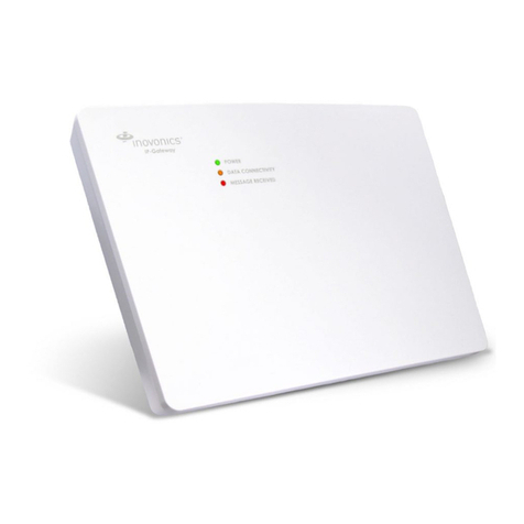
Once the IP gateway is functional and all transmitter TXIDs have been
registered, the LEDs will function as follows:
• Green: Blinks when powering up; solid when power up is complete.
• Orange: Blinks while establishing an IP connection; solid when IP
connected.
• Red: Blinks upon message receipt from any transmitter.
3 Tips and Notes
3.1 Installation Notes
• These products are designed to be maintained by professional
technicians.
• Products are tested for indoor use.
• Inovonics recommends registering and testing end devices prior to
installation, using a floor plan or something similar to indicate
installation locations. Consider marking or applying descriptive labels
to the end device cases to ensure proper installation. Conduct a site
survey with an Inovonics survey kit prior to installation to assist with
RF gateway, repeater and end device placement.
• Use a brand name USB flash drive with a FAT32 (vfat) filesystem for
configuration.
• The IP gateway configuration file is YAML formatted. See yaml.org
for details.
• If using line power, keep cable length to less than 3 meters to
minimize noise pickup.
• To resolve connectivity issues, check for loose/disconnected cabling,
ensure power to Ethernet routers and/or switches, and connect a
laptop to the Ethernet cable attached to the IP gateway’s RJ45 port
and attempt to open a web site. If you are still unable to establish an
Internet connection, contact a facility IT representative.
• Metal will reduce radio frequency (RF) range. Mount the IP gateway
in a location removed from metal, including duct work, wire mesh
screens, IT closets, metal boxes, and etc. For additional information,
see the "EchoStream Device Installation Recommendation" tech
note at www.inovonics.com.
• The EchoStream system should be tested regularly to ensure
operation. To test, place the system in test mode, activate an end
device, and ensure an appropriate response.
4 Questions
If you have any problems with this procedure, contact Inovonics technical
services:
• E-mail: [email protected].
• Phone: (800) 782-2709; (303) 939-9336.
5 Specification
Dimensions: 243 mm x 169 mm x 31 mm (9.556” x 6.65” x 1.208”).
Power requirement: 12-14V AC intrinsically safe power supply capable of
supplying at least 20VA, or a 12-15V DC power supply capable of
supplying at least 15W; IEEE 802.3af-2003 and current safety standard
(e.g. IEC 60950-1 or IEC 62368-1) compliant PoE supply (e.g. injector or
network switch).
Ethernet 10/100 BASE-T, DHCP, static IP.
RF frequency range: EchoStream: 868 MHz; Wi-Fi® and Bluetooth®:
2.400 GHz to 2.485 GHz.
RF power (WiFi): Up to 17.5 dBm.
Operating environment Temperature: 0°F to 60°C; humidity: Up to 90%
non-condensing.
Firmware Revision: 90549, v3.00 (EE4000 embedded receiver).
Countries in which Inovonics European products can be distributed:
Belgium, Bulgaria, Croatia, Cyprus, Czech Republic, Denmark, Estonia,
Finland, France, Greece, Hungary, Ireland, Italy, Latvia, Lithuania,
Luxembourg, Malta, Netherlands, Norway, Poland, Portugal, Romania,
Slovakia, Slovenia, Spain, Sweden, United Kingdom.
6 Simplified Declaration of Conformity
Hereby, Inovonics declares that the radio equipment type EE4080 is in
compliance with Directive 2014/53/EU.
The full text of the EU declaration of conformity is available at the following
Internet address: www.inovonics.com
7 Open Source Software Notice and Information
To obtain the source code under GPL, LGPL, MPL, and other open source
licenses that is contained in this product, please contact Inovonics
technical services. In addition to the source code, all referred license terms,
warranty disclaimers and copyright notices are also available.
14 Use a Phillips screwdriver to close the IP gateway housing.
(800) 782-2709; (303) 939-9336
www.inovonics.com
For product and installation videos visit us at
www.inovonics.com/videos or use the QR
code below.
Other Inovonics Gateway manuals

Inovonics
Inovonics E 4080 Series User manual

Inovonics
Inovonics EN7380 User manual

Inovonics
Inovonics TapWatch Gateway User manual

Inovonics
Inovonics EN6080 User manual

Inovonics
Inovonics EN7295 User manual

Inovonics
Inovonics EN6080 User manual

Inovonics
Inovonics TapWatch Gateway EN7580 User manual

Inovonics
Inovonics EN4080 User manual

Inovonics
Inovonics EN6080 User manual