Four-Faith F8L10GW User manual

F8L10GW LoRa Gateway
User Manual
FCC ID:2ALUW-F8L10GW

F8L10GW LoRa Gateway
Page 2 of 37
Add:11th Floor,A-06 Area, No.370, Chengyi Street, Jimei, Xiamen, Fujian, China.
http://www.four-faith.com Tel:+86-592-6307217 Fax: +86-592-5912735
Files Revised Record
Date
Version
Remark
Author
2018.07.19
V1.0.0
Initial version
Cheney/Carolin
2018.10.11
V1.0.1
Add 1-3 system block diagram;
Modify document format;
Document style adjust;
Font size adjustment.
Jim

F8L10GW LoRa Gateway
Page 3 of 37
Add:11th Floor,A-06 Area, No.370, Chengyi Street, Jimei, Xiamen, Fujian, China.
http://www.four-faith.com Tel:+86-592-6307217 Fax: +86-592-5912735
Copyright Notice
All contents in the files are protected by copyright law, and all copyrights are reserved by
Xiamen Four-Faith Communication Technology Co., Ltd. Without written permission, all
commercial use of the files from Four-Faith are forbidden, such as copy, distribute,
reproduce the files, etc., but non-commercial purpose, downloaded or printed by individual
(all files shall be not revised, and the copyright and other proprietorship notice shall be
reserved) are welcome.
Trademark Notice
Four-Faith、四信、 、 、 are all registered trademarks of
Xiamen Four-Faith Communication Technology Co., Ltd., illegal use of the name of
Four-Faith, trademarks and other marks of Four-Faith is forbidden, unless written
permission is authorized in advance.

F8L10GW LoRa Gateway
Page 4 of 37
Add:11th Floor,A-06 Area, No.370, Chengyi Street, Jimei, Xiamen, Fujian, China.
http://www.four-faith.com Tel:+86-592-6307217 Fax: +86-592-5912735
Pole-mounted Installation
Wall-mounted Installation
Note:Accessories are subject to the purchased model.

F8L10GW LoRa Gateway
Page 5 of 37
Add:11th Floor,A-06 Area, No.370, Chengyi Street, Jimei, Xiamen, Fujian, China.
http://www.four-faith.com Tel:+86-592-6307217 Fax: +86-592-5912735
C
Co
on
nt
te
en
nt
ts
s
Chapter 1 Brief Introduction..........................................................................................................6
1.1 General................................................................................................................................6
1.2 Features and Benefits..........................................................................................................7
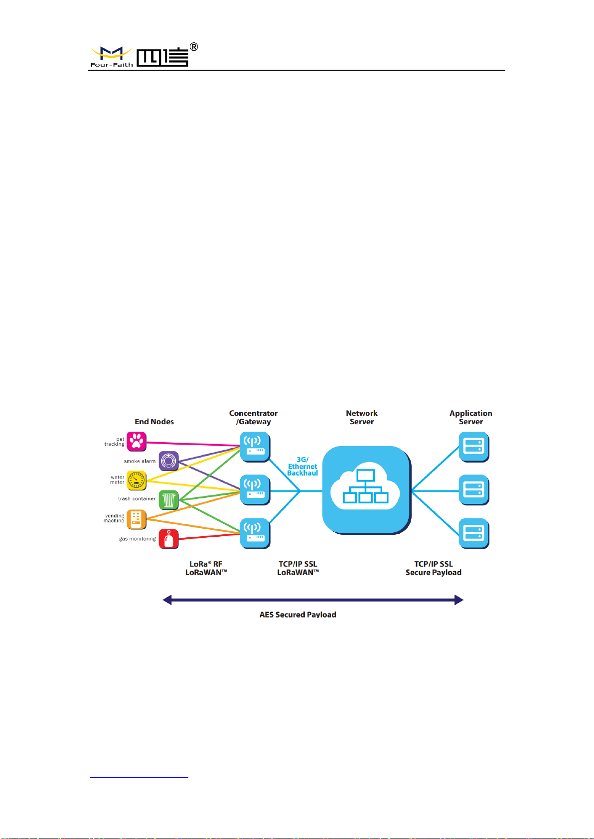
1.3 Working Principle ...............................................................................................................7
1.4 Specifications......................................................................................................................8
Chapter 2 Installation Instruction ...............................................................................................11
2.1 General..............................................................................................................................11
2.2 Packing List ......................................................................................................................11
2.2.1. Wall-mounted Packing List...............................................................................11
2.2.2. Pole-mounted Packing List..............................................................................11
2.3 Installation.........................................................................................................................12
2.3.1 SIM/UIM Installation...........................................................................................12
2.3.2 Wall-mounted Installation..................................................................................13
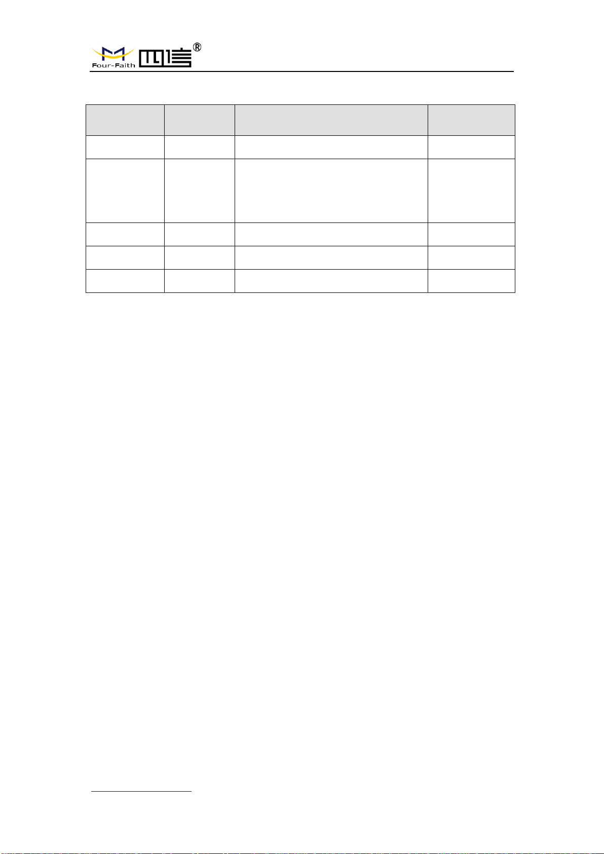
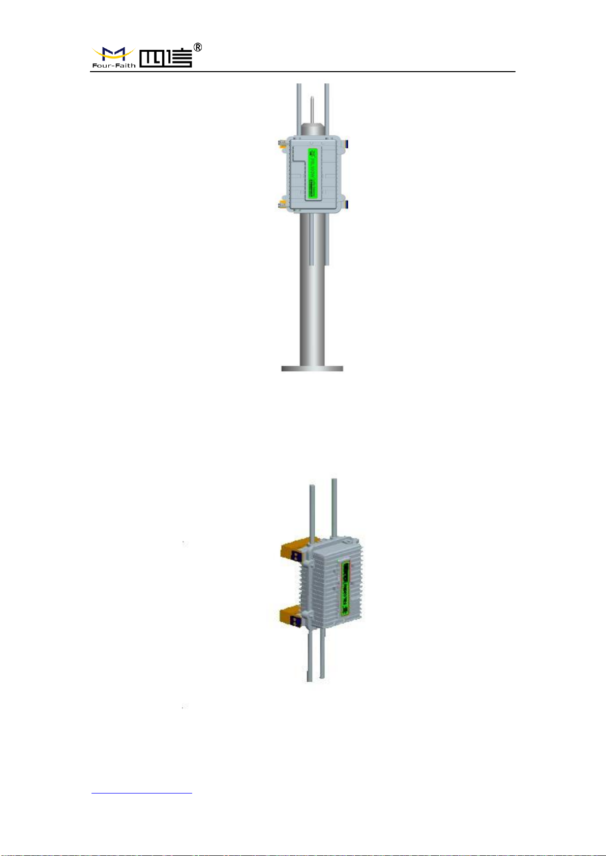
2.3.3 Pole-mounted Installation..................................................................................16
2.3.4 Antenna Installation............................................................................................17
2.4 Indicator light description.................................................................................................18
Chapter 3 Configuration..............................................................................................................20
3.1 Configuration Connection.................................................................................................20
3.2 Access to Configuration Web Page...................................................................................20
3.2.1 IPAddress Setting..............................................................................................20
3.2.2 Login configuration web page...........................................................................21
3.3 Management & Configuration ..........................................................................................23
3.3.1 Connection Setting.............................................................................................23
3.3.2 WiFi.......................................................................................................................25
3.3.2.1 Basic Configuration ....................................................................................26
3.3.3 LoRaWAN Application........................................................................................27
3.3.4 ADMINISTER......................................................................................................28
3.3.4.1 ADMINISTER ............................................................................................28
3.3.4.2 The factory default......................................................................................31
3.3.4.3 Firmware Upgrade ......................................................................................32
3.3.4.4 Backup ........................................................................................................32
3.3.5 State......................................................................................................................34
3.3.5.1 F8L10GW ...................................................................................................34
Appendix........................................................................................................................................36

F8L10GW LoRa Gateway
Page 6 of 37
Add:11th Floor,A-06 Area, No.370, Chengyi Street, Jimei, Xiamen, Fujian, China.
http://www.four-faith.com Tel:+86-592-6307217 Fax: +86-592-5912735
Chapter 1 Brief Introduction
1.1 General
F8L10GW LoRa Gateway is a wireless communication base station based on
LoRaWAN protocol. It connects to LoRaWAN terminals of various applications and
transmits terminal data to the cloud through 3G/4G or wired Ethernet. SupportWiFi
wireless configuration management and online upgrade, GPS positioning, AC power
supply.
F8L10GW is complied with standard LoRaWAN protocol, it’s compatible with
LoRaWAN devices and NS. The product has been widely used in M2M industry, smart
grid, smart transportation, industrial automation, intelligent buildings, fire control, public
security, environmental protection, meteorology, digital medical treatment, telemetry,
military, space exploration, agriculture, forestry, water, mining, petrochemical and other
fields.

F8L10GW LoRa Gateway
Page 7 of 37
Add:11th Floor,A-06 Area, No.370, Chengyi Street, Jimei, Xiamen, Fujian, China.
http://www.four-faith.com Tel:+86-592-6307217 Fax: +86-592-5912735
1.2 Features and Benefits
Design for Industrial Application
High performance industrial wireless communication module.
High performance industrial multi-channel LoRaWAN RF base station chip.
Aluminum housing, IP65 rated.
SupportAC Power supply
Stability and Reliability
WDT watchdog design.
Complete anti-drop mechanism ensures data terminal always online.
Built-in 1.5 KV electromagnetic isolation protection in Ethernet interface.
Built-in 15KV ESD protection in SIM/UIM card interface.
Built-in reverse phase protection, over voltage protection and lightning protection.
Antenna lightning protection.
1.3 Working Principle
The principle chart of the F8L10GW LoRa Gatwway is as following:

F8L10GW LoRa Gateway
Page 8 of 37
Add:11th Floor,A-06 Area, No.370, Chengyi Street, Jimei, Xiamen, Fujian, China.
http://www.four-faith.com Tel:+86-592-6307217 Fax: +86-592-5912735
1.4 Specifications
Communication Network: Start topology.
Supported LoRaWAN protocol: Class A and Class B*, Class C.
Supported frequency: EU863-870.
Urban communication range: 6km.
Maximum receiving sensitivity: Max -142dbm @LoRa; -70dbm @WIFI.
8 upstream channels,1 downstream channel.
Safe and reliable, low latency, wireless transmission technology.
Adaptive data rate.
Work mode: support sending and receiving different frequency, same frequency.
Positioning function: GPS.
Network connectivity: 3G / 4G, Ethernet.
Management: WiFi wireless management and upgrade.
TF card local storage supported.
Operating temperature: -35~+50℃.
Dimensions: 289.4*223.62*115 mm.
IP65 rated.
Power supply:100-240V 50/60Hz, 0.8A.
Electrical Performance.
No.
Parameter
Technical Data
1
Rated input voltage
100~240V AC
2
Rated output voltage
12V
3
Rated output current
3A
4
Input undervoltage protection
No
5
Output overvoltage protection
Yes
6
Output overcurrent protection
Yes
7
Short circuit protection
Yes
8
Lightning protection level
3KA
9
Input wire diameter
5-7mm
Cellular Specification
ITEM
CONTENT
Frequency Band
FDD-LTE Band 2/4/5/7/17
DC-HSPA/HSPA+/HSDPA/ HSUPA/WCDMA Band 1/8
GSM850 / PCS1900

F8L10GW LoRa Gateway
Page 9 of 37
Add:11th Floor,A-06 Area, No.370, Chengyi Street, Jimei, Xiamen, Fujian, China.
http://www.four-faith.com Tel:+86-592-6307217 Fax: +86-592-5912735
WIFI Specification
Item
Content
Standard
IEEE802.11b/g/n
Security
WEP, WPA, WPA2, etc.
Frequency Range
2412MHz to 2462MHz
LoRa Specification
Item
Content
Communication Protocol and Band
902MHz to 928MHz(US)
GPS RX Specification
Item
Content
Frequency Band
1559MHz to 1610MHz
Operating Frequency:
1575.42MHz
Power supply
Item
Content
Input Power
100-240V 50/60Hz, 0.8A
Output Power
12V 3.0A
Note: The power plug considered as disconnect device of Power Supply.
Environmental Limits
Item
Content
Operating Temperature
-35~50ºC
Note 1:Do not use the products in the environment at too high or too low temperature.
The suitable temperature for the product and accessories is -35℃-50℃.
Antenna Specification
Item
Content
LoRa antenna
N-type female, Omni-Directional FRPAntenna , 2dBi gain
GPS antenna
N-type female, Omni-Directional FRPAntenna , 2dBi gain
WiFi antenna
N-type female, Omni-Directional FRPAntenna , 2dBi gain.
WWAN antenna
N-type female, Omni-Directional FRPAntenna , 0dBi gain
Note 1: Please ensure to use only the antenna offered by the manufacturer. Using
unauthorized antenna may cause danger and violate the authorization
Note 2: Antenna connector ( N-type ) was not unique connector, need installed by
trained, professional engineer

F8L10GW LoRa Gateway
Page 10 of 37
Add:11th Floor,A-06 Area, No.370, Chengyi Street, Jimei, Xiamen, Fujian, China.
http://www.four-faith.com Tel:+86-592-6307217 Fax: +86-592-5912735
Federal Communication Commission (FCC) Radiation Exposure
Statement
The device has been evaluated to meet general RF exposure requirement,
The device can be used in portable exposure condition without restriction
Federal Communication Commission (FCC) Radiation Exposure Statement
Power is so low that no RF exposure calculation is needed.
This device complies with part 15 of the FCC rules. Operation is subject to the
following two conditions: (1) this device may not cause harmful interference,
and (2) this device must accept any interference received, including
interference that may cause undesired operation.
NOTE: The manufacturer is not responsible for any radio or TV interference
caused by unauthorized modifications or changes to this equipment. Such
modifications or changes could void the user’s authority to operate the
equipment.
NOTE: This equipment has been tested and found to comply with the limits for
a Class B digital device, pursuant to part 15 of the FCC Rules. These limits are
designed to provide reasonable protection against harmful interference in a
residential installation. This equipment generates uses and can radiate radio
frequency energy and, if not installed and used in accordance with the
instructions, may cause harmful interference to radio communications.
However, there is no guarantee that interference will not occur in a particular
installation. If this equipment does cause harmful interference to radio or
television reception, which can be determined by turning the equipment off and
on, the user is encouraged to try to correct the interference by one or more of
the following measures:
‐Reorient or relocate the receiving antenna.
‐Increase the separation between the equipment and receiver.
‐Connect the equipment into an outlet on a circuit different from that to which
the receiver is connected.
‐Consult the dealer or an experienced radio/TV technician for help.
FCC Caution: Any changes or modifications not expressly approved by the
party responsible for compliance could void the user's authority to operate this
equipment.

F8L10GW LoRa Gateway
Page 11 of 37
Add:11th Floor,A-06 Area, No.370, Chengyi Street, Jimei, Xiamen, Fujian, China.
http://www.four-faith.com Tel:+86-592-6307217 Fax: +86-592-5912735
Chapter 2 Installation Instruction
2.1 General
F8L10GW must be installed correctly in order to achieve the design function. The
installation must be conducted by a qualified engineer recognized by the Four-Faith.
Warning:
1. Power off before installation.
2. Don’t remove the cover, power interface, antenna interface.
2.2 Packing List
2.2.1. Wall-mounted Packing List
Item
Qty
Remark
F8L10GW LoRa Gateway
1
4G Omni-Directional FRPAntenna
1
Optional
WIFI Omni-Directional FRPAntenna
1
GPS Omni-Directional FRPAntenna
1
LoRa Omni-Directional FRPAntenna
1
Bracket
1
Swelling screw ø14mm
3
Wire
1
Optional
User manual CD
1
Optional
QC passed card
1
Warranty card
1
2.2.2. Pole-mounted Packing List
Item
Qty
Remark
F8L10GW gateway
1
4G Omni-Directional FRPAntenna
1
Optional
WIFI Omni-Directional FRPAntenna
1
GPS Omni-Directional FRPAntenna
1
LoRa Omni-Directional FRPAntenna
1
Bracket
2
Wire
1
Optional
User manual CD
1
Optional

F8L10GW LoRa Gateway
Page 12 of 37
Add:11th Floor,A-06 Area, No.370, Chengyi Street, Jimei, Xiamen, Fujian, China.
http://www.four-faith.com Tel:+86-592-6307217 Fax: +86-592-5912735
QC passed card
1
Warranty card
1
2.3 Installation
F8L10GW Dimensions
2.3.1 SIM/UIM Installation
1. Cut off the power.
2. Unscrew the M6 screws, figure. 2.3.1 as below.
3. Insert SIM/UIM card, figure 2.3.2 as below.
4. Push the SIM/UIM card and the card will pop up automatically.
5. Tighten M6 screws.
Warning:
1. Power must be off before installing SIM/UIM card.
2. M6 screws must be tightened and fixed.

F8L10GW LoRa Gateway
Page 13 of 37
Add:11th Floor,A-06 Area, No.370, Chengyi Street, Jimei, Xiamen, Fujian, China.
http://www.four-faith.com Tel:+86-592-6307217 Fax: +86-592-5912735
Figure 2-3-1 Unscrew the M6 screws
Figure 2-3-2 Insert SIM/UIM card
2.3.2 Wall-mounted Installation
Step 1: The wall where the gateway is installed must be flat and open-sided, make
sure no shield within 5 meters around LoRa antenna. Drill 3 holes of ø14mm
diameter, 60 mm depth (swelling screw is about 50mm long) according to the
position of the bracket mounting holes, Figure 2-3-3.
(Note: Press the shelf against the wall, mark it, and then punch the hole in the wall.)

F8L10GW LoRa Gateway
Page 14 of 37
Add:11th Floor,A-06 Area, No.370, Chengyi Street, Jimei, Xiamen, Fujian, China.
http://www.four-faith.com Tel:+86-592-6307217 Fax: +86-592-5912735
Figure 2-3-3 Hole Location Diagram
Step 2: Fix the swelling screws in the bracket, Figure 2-3-4.
Figure 2-3-4 Swelling Screws Installation Diagram
Step 3: Fix the bracket on the wall and tighten the screw, Figure 2-3-5.

F8L10GW LoRa Gateway
Page 15 of 37
Add:11th Floor,A-06 Area, No.370, Chengyi Street, Jimei, Xiamen, Fujian, China.
http://www.four-faith.com Tel:+86-592-6307217 Fax: +86-592-5912735
Figure 2-3-5 Bracket Installation Diagram
Step 4: Tighten the four screws and fix the gateway on the bracket, then install the
antenna, Figure 2-3-6.

F8L10GW LoRa Gateway
Page 16 of 37
Add:11th Floor,A-06 Area, No.370, Chengyi Street, Jimei, Xiamen, Fujian, China.
http://www.four-faith.com Tel:+86-592-6307217 Fax: +86-592-5912735
Figure 2-3-6 Fix Four Screws Diagram
2.3.3 Pole-mounted Installation
Step 1: Prepare a pole with 70~90mm diameter, make sure no shield within 5
meters around LoRa antenna.
Step 2: Put the clamp into the pole, fix the clamp in the pole with screws.

F8L10GW LoRa Gateway
Page 17 of 37
Add:11th Floor,A-06 Area, No.370, Chengyi Street, Jimei, Xiamen, Fujian, China.
http://www.four-faith.com Tel:+86-592-6307217 Fax: +86-592-5912735
Note: Pole is not included in the product.
2.3.4 Antenna Installation
After gateway is installed on the wall or pole, connect the Matching antennas to the
antenna interface.Make sure the antennas are tightened to get best signal. Fig. 2.3.7
Note: Each antenna must install to the right interface and Using a tool to tighten,
otherwise the gateway won’t work properly and waterproof.

F8L10GW LoRa Gateway
Page 18 of 37
Add:11th Floor,A-06 Area, No.370, Chengyi Street, Jimei, Xiamen, Fujian, China.
http://www.four-faith.com Tel:+86-592-6307217 Fax: +86-592-5912735
Fig. 2.3.7
2.4 Indicator light description
The F8L10GW offers the following indicators: Power, System, Online, SIM, LoRa,
WAN, WIFI, Signal Strength. Status description of each indicator are as below:
Indicator light
Status
Description
PWR
Red light on
Power on
Red light off
Power off
SYS
Yellow light flash
System work properly
Yellow light off
System work improperly
WIFI
Blue light on
WIFI on
Blue light off
WIFI off
LoRa
Green light on
LoRa normal

F8L10GW LoRa Gateway
Page 19 of 37
Add:11th Floor,A-06 Area, No.370, Chengyi Street, Jimei, Xiamen, Fujian, China.
http://www.four-faith.com Tel:+86-592-6307217 Fax: +86-592-5912735
Green light off
LoRa abnormal
Green light flash
Data Transmitting
3G/4G Signal
Turn on an light
Weak signal strength (less
than -90db)
Turn on two lights
Medium signal strength
(-70db~-90db)
Turn on three lights
Better signal strength (greater
than -70db)
Online
Green light off
Online
Green light on
Offline

F8L10GW LoRa Gateway
Page 20 of 37
Add:11th Floor,A-06 Area, No.370, Chengyi Street, Jimei, Xiamen, Fujian, China.
http://www.four-faith.com Tel:+86-592-6307217 Fax: +86-592-5912735
Chapter 3 Configuration
3.1 Configuration Connection
Before configuring the F8L10GW, connect the F8L10GW and the PC network cable or
WIFI. When connect with network cable, one end is connected to any Ethernet interface of
F8L10GW "Local Network" (LAN port), and the other end is connected to the Ethernet
interface of PC. When connect with WIFI, the default SSID of F8L10GW is "FOUR-FAITH"
without password verification.
3.2 Access to Configuration Web Page
3.2.1 IP Address Setting
Specify IP address
Set the IP address of PC as 192.168.1.9(or other IP address of 192.168.1 network
segment), the subnet mask as 255.255.255.0, and the default gateway as
192.168.1.1.DNS as a locally available DNS server.
Other manuals for F8L10GW
1
Table of contents
Other Four-Faith Gateway manuals
Popular Gateway manuals by other brands

Fortress Power
Fortress Power Guardian Installation and operation manual

Ubiquiti
Ubiquiti UniFi quick start guide

Leviton
Leviton Internet Gateway instructions

RTA
RTA 460ESDFM-N2EW Product user guide

Technicolor
Technicolor DWA0120 Setup and user guide

Motorola
Motorola 2247-62-10NA - Netopia 2247-62 Wireless... user manual